Chamberlain LiftMaster SCS500 Owner's manual
- Category
- Gate Opener
- Type
- Owner's manual

®
®
Anleitungen - Torantrieb SCS500-24
Instructions - Ouvre-Portail SCS500-24
Instructions - Gate Operator SCS500-24
Instrucciones - Automatismo de Puerta SCS500-24
Istruzioni - Automazioni per Cancelli SCS500-24
Instrukties - Automatische hekaandrijving SCS500-24
Instruções – Automatismos para portões SCS500-24
de
fr
en
es
it
nl
pt
Page is loading ...
Page is loading ...
Page is loading ...
Page is loading ...
Page is loading ...
Page is loading ...

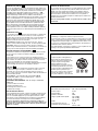
Contents: General advice on installation and
use:
Contents list: page 1
Content of the carton: figure
Before you begin: page 2
Checklist: page 2
Gate types/installation height:
page 2, figure A-F
Gate configuration:
page 2, figure A-F
Gate stops:
page 2, figure A-F
Assembly measurements and opening
angle: page 3, figures A-B
Post bracket/Gate fixing bracket:
page 2, figures A-C + A-C
Release of drive arms:
page 3, figure A
Installing the drive arms:
page 3, figure B
Wiring: page 3, figure A-B
Maintenance work: page 3
Initial Operation: page 3
Technical Data: page 3
Disposal: page 3
Replacement Parts: figure
Max. gate weights and sizes: page 10
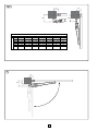
CONTENT OF THE CARTON
(1) Motor SCS
(2) Postbracket, screw and nut
(3) Keys per motor (2)
(4) Gate fixing bracket, washer and nut
(5) Manual (1)
1
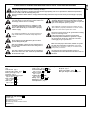
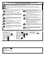
PLEASE START BY READING THESE IMPORTANT SAFETY RULES • SAVE THESE INSTRUCTIONS
This safety alert symbol means "Caution" - failure to comply with such an instruction involves risk of personal injury or
damage to property. Please read these warnings carefully.
This gate drive mechanism is designed and tested to offer appropriately safe service provided it is installed and operated in
strict accordance with the following safety rules.
Incorrect installation and/or failure to comply with the following instructions may result in serious personal injury or property
damage.
1
2
3
3
5
7
7
8
Installation and wiring must be in compliance with
your local building and electrical installation codes.
Power cables must only be connected to a properly
earthed supply.
Any entrapment possibility by the moving wing between
wing & walls must be secured with safety edges or IR-
sensors.
Disconnect electric power to the system before making
repairs or removing covers.
A disconnecting device must be provided in the
permanently-wired installation to guarantee all-pole
disconnection by means of a switch (at least 3mm
contact gap) or by a separate fuse.
When using tools and small parts to install or carry
out repair work on a gate exercise caution and do not
wear rings, watches or loose clothing.
Make sure that people who install, maintain or operate
the gate drive follow these instructions. Keep these
instructions in a safe place so that you can refer to them
quickly when you need to.
Please remove any locks fitted to the gate in order to
prevent damage to the gate.
It is important to make sure that the gate always runs
smoothly. Gates which stick or jam must be repaired
immediately. Employ a qualified technician to repair the
gate, never attempt to repair it yourself.
Keep additional accessories away from children. Do not
allow children to play with pushbuttons or remote controls.
A gate can cause serious injuries as it closes.
After the installation a final test of the full function of
the system and the full function of the safety devices
must be done.
The full protection against potential squeeze or
entrappment must work direct when the drive arms are
installed.
This drive cannot be used with a gate incorporating a
wicket door unless the drive cannot be operated with
the wicket door open.
4
9
6
1-en

GATE CONFIGURATION
How far must the gate leaf open?
90 degrees or up to 115 degrees. An opening angle in excess of 115
degrees is possible to a limited extent but is not recommended.
Reason: the drive mechanism always runs at the same speed. The
further the gate has to be opened, the faster the gate leaf must
travel. Movement becomes more erratic and this subjects the fittings
and gate to extreme stresses (see 3A-F).
Tip for professionals: The time taken to reach the limit stop can be
controlled by deliberately selecting different A and B dimensions (left
+ right). However, this method of installing subjects the fittings to
high stresses and can cause the gate to run erratically. It is
recommended that only experienced gate installers adopt this
method.
GATE STOPS
A SWING GATE NEEDS A FIXED GATE STOP IN BOTH THE
OPEN AND CLOSE DIRECTIONS. Gate stops save wear and tear
on the drive mechanism, gate and fittings. Operating a gate without
fixed limit stops results in poor performance. It is often dangerous,
leads to premature wear and voids your warranty!
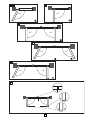
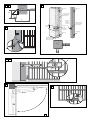
POST FIXING BRACKET
Choosing the correct location for the post fixing bracket has a
decisive impact on the subsequent functioning of the system. It
determines the distance between the motor's centre of motion and
the gate's centre of motion and hence the opening angle. These
dimensions are referred to as dimension A and dimension B. Do
not underestimate the effect that these dimensions have on correct
functioning and running. Try and achieve the best dimension for your
opening angle, as precisely as possible and suitable for all
circumstances. See Table (figure 4A-B) for dimensions A/B.
If the post is not wide enough, an extension piece must be fitted to it
(figure 5A). If the post is too thick, cut out part of it to make it thinner
(figure 5B).
To obtain ideal dimensions, it may be necessary to shorten or
lengthen the supplied hinge plate. In the case of gates that are to be
custom made, if the gate hinges are fitted on the posts appropriately,
it is possible to influence dimensions A and B. Before the final
mounting dimensions are determined, you should always check
whether or not there is any possibility that the corner of the drive
mechanism will hit the post as the gate swings.
INSTALLATION: The drive mechanism exerts considerable force
against the post. Usually, acceptable mounting dimensions are
obtained if the supplied hinge plate is welded directly onto the post.
In the case of thick stone or concrete posts, the hinge must be
welded to a base plate and attached so that the plugs cannot work
loose during operation. Heavy-duty plugs where a threaded rod is
bonded into the masonry stress-free are more suitable for this
purpose than steel or plastic straddling plugs. In the case of
brickwork pillars, bolt on a relatively large steel plate that covers
several bricks and then weld the hinge plate to it. An angle plate
attached over the corner of the post is also a good means of fixing
the operators.
BEFORE YOU BEGIN
The drive mechanism needs room to the side permitting correct
installation of drive arms. Please make sure that this is available.
Gates affected by high wind loads must also be protected by an
(electric) lock.
There are many factors to consider when choosing the right drive
mechanism. Assuming that a gate functions properly, "startup" is the
most difficult phase, once the gate is in motion, significantly less force
is usually required to move it.
• Gate size: Gate size is a very important factor. Wind can brake or
distort the gate, thereby increasing the amount of force needed to
move it considerably.
• Gate weight: The weight of the gate in not as relevant as the size.
• Effect of temperature: Low outdoor temperatures can make initial
startup more difficult (changes in the ground, etc.) or even prevent
it.
• Operating frequency/Duty cycle:
24 volt drives can run permanently.
INSTALLATION CHECKLIST - PREPARATIONS
Check the carton contents and read the instructions carefully. Make
sure your gate equipment operates perfectly. The gate must run
evenly and smoothly and must not stick at any point. Remember that
the ground level may be several centimeters higher in winter. The
gate must be stable and as free of backlash as possible in order to
prevent any unwanted to and fro movement. The more smoothly the
gate leaf runs, the more sensitive the force adjustment must be.
Note down any materials you still need and obtain them before
starting to install. Heavy-duty plugs, bolts, gate stops, cables,
distribution boxes, tools, etc.
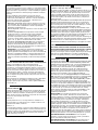
GATE TYPES
The gate type determines the location where the drive mechanism is
installed. If the gate stop is on the ground, the drive mechanism must
also be installed at a height that is as low as possible so that it
cannot twist the gate. Use only parts of the gate frame for fixing
purposes.
TYPE A, B, C
For steel gates, the gate fitting must be attached to the main frame.
If you are uncertain whether the available support is sufficiently
stable, reinforce it.
TYPE D, E, F
In the case of wooden gates, the gate fitting must be through bolted.
It is advisable to fit a plate from the outside so that the fixing
brackets cannot become loose over time. Thin wooden gates must
also be reinforced in order to withstand the stresses encountered
(e.g. type F).
2
3
5
2-en

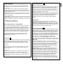
MAINTENANCE WORK
The drive mechanism is maintenance free. Check that the gate fittings
and the drive mechanism are securely fixed at regular intervals
(monthly). Release the drive and check that the gate functions properly.
Unless the gate runs smoothly it will not operate correctly with the drive
mechanism. The drive cannot eliminate the problems caused by a gate
that does not work satisfactorily.
24Volt drives: also see owners manual of Electronic Control.
GATE FITTING
The gate fitting must be installed so that it is horizontal relative to the
post bracket (6A). The distance between the gate bracket and post
bracket is referred to as the "arm span". When the gate is closed, the
drive mechanism is 99% extended. When the gate is opened, the
drive mechanism is 1% extended (6B). Fully retracting or extending
the plunger/spindle in operation (with gate) damages the drive
mechanism and voids the warranty. It is absolutely imperative to
comply with the required arm span under all circumstances!
For steel gates, fixings should be welded on or through bolted (6C).
When through bolting the gate, use large washers or a plate on the
other side. The drive mechanism exerts an extremely high force on this
joint.
Fixings must be through bolted for wooden gates. Wood deflects
under load and the bolt will become loose. Due to movement caused
by repeated loading, the wood deflects more and more until the gate
no longer closes correctly and has to be repaired.
Fit a reinforcing plate from the outside and one on the inside so that
the wood cannot deflect and the joint cannot become loose.
Thin wooden gates without a metal frame must also be reinforced in
order to withstand continuous stresses (e.g. type F).
RELEASE
The drive mechanism can be released. The gate can then be opened
and operated manually (power failure). With a new drive mechanism,
the release action may sometimes feel stiff/jerky. This is normal and
has no effect on function.
Release: Insert the key in the cylinder lock and turn it 180 degrees.
Then turn the release lever 180 degrees – done (7A)!
Engage: Turn the lever glockwise. As soon as the gate moves or the
drive runs, the gear locks again. Use the lock to protect the lever
against unauthorized release.
INSTALLING THE DRIVE ARMS
Release the drive. Push the released drive onto the fittings and
secure it by using the supplied bolts, nuts and rings (7B).
„If the centre or inner hole, on the hinge plate, is used to fix the post
fixing bracket you MUST cut away the remaining section of the hinge
plate before activating the arms. Failure to do so will result in
breaking the fixing bracket“.
Do not use a hammer when you mount the operator on the bracket.
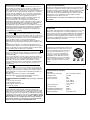
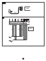
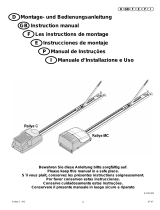
WIRING
24 VOLT: The connecting cable has 6 wires, is approx. 200 cm long
and is run in a curve to the control unit or to a watertight distribution
box located above ground. A permanent connection is formed from
the distributor box via an appropriate cable.
Connection: See control unit instructions (8A-B).
Cable colours: Brown/Green/White/Yellow=sensors
Blue/Red: 24 volt motor.
ACCESSORY TIP: Extension cable LA400-JB40
Contains:
(1) 12m cable with terminals
(1) Distribution box IP65
(2) Strain relief PG 13,5
(1) Mounting material
INIATIAL OPERATION
Check functionality in a disengaged state with the hand on the gate.
Initial electrical operation is only possible with a suitable control unit that
can be purchased as an accessory. Ensure at all times that mechanical
and electrical safety instructions applying to the given installation are
complied with.
Should the force of the moving wing at its closing edge be higher
than 400N , then additional safety facilities (light barrier, contact
strip) must be used. Any safety facilities must comply with the
requirements set out in EN60335-2-103.
5
7
7
8
TECHNICAL DATA
Mains supply (Motor)
Motorspannung
Current consumption
Power consumption
Max. gate width / weight
Protection Class
Opening time 90° sec.
Temperature
220 – 240 Volt
˜
/ 50 - 60 Hz
24 VDC
10A
240W
2.5m / 700kg
4.0m / 450 kg
5.5m / 250 kg
I - IP 44
approx. 32
-40
o
C up to + 60
o
C
DISPOSAL
The packaging is made from environmentally friendly materials. It can
be disposed of in the local recycling bin. According to the European
Directive 2002/96/EC on waste electrical and electronic equipment,
this device must be properly disposed of after use to ensure the reuse
of materials. The information on the possibilities of this waste disposal
is provided by the local government or municipality.
BATTERY DISPOSAL
Batteries and rechargeable batteries may not
be disposed along with domestic waste, but
are obliged to be returned.
After use they can be returned free of charge
locally e.g. in trade or at municipal collecting
points.
Batteries and rechargeable batteries are
marked with a crossed waste container as
well as with the chemical symbol which
describes their toxic element, “Cd” for
cadmium, “Hg” for mercury and “Pb” for lead.
12VDC
Pb Cd Hg
3-en
Page is loading ...
Page is loading ...
Page is loading ...
Page is loading ...
Page is loading ...
Page is loading ...
Page is loading ...
Page is loading ...
Page is loading ...
Page is loading ...
Page is loading ...
Page is loading ...

Key (2)
14.8 cm
10.7 cm
102.5 cm
Post Bracket
Gate Bracket
2 A
B
C D
E F
1
4
Page is loading ...
Page is loading ...

Top View
B
A
NOTE: Weld Re Bar
Behind Gate Hinges for
Maximum Strength.
Gate Hinge
Top View
25 cm
Minimum
Heavy Steel
Bracket
(Reinforce if
necessary)
Back Steel Plates
for Reinforcement
(Not provided)
Gate Hinge
Gate Hinge
Gate Hinge
Back Steel
Bracket
(Reinforce if
necessary)
Heavy Steel Plate
for Reinforcement
(Not provided)
Post Install
Column Install
5 A
B
C
~ 57 mm
Gate Bracket Location
~ 250 mm
~ 900 mm
~ 160 mm
6 A
C
B
7
Page is loading ...

1 Brown
2 Green
3 White
4 Yellow
5 Blue
6 Red
CB24
24Volt
RED
RED
BLUE
BLUE
30VDC
MOTOR
MASTER
MOTOR
SECOND 24V/150mA
BRN GRN WHT YEL
MASTER
BRN GRN WHT YEL
SECOND
LI
G
CON
T
BROWN
GREEN
WHITE
BROWN
GREEN
WHITE
YELLOW
YELLOW
CB124
8 A
B
9

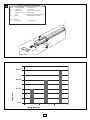
GATE OPERATOR ARM
ITEM PART NUMBER DESCRIPTION
11 SCS500-24 Primary Arm
12 KSWG-0623 Rear Connector with Pin
13 41ASWG-0119 Release Keys
14 Q230 Steel Bracket Mounting Plates
15 Q232 Bottom Washer and Nut
NOT SHOWN
K77-36389 Hardware Bag
14
15
11
12
13
14
9
0m
2.5 m
4.0 m
700 kg 450 kg 250 kg
Wing Weight
Wing Size
5.5 m
10
Page is loading ...
Page is loading ...
Page is loading ...
-
 1
1
-
 2
2
-
 3
3
-
 4
4
-
 5
5
-
 6
6
-
 7
7
-
 8
8
-
 9
9
-
 10
10
-
 11
11
-
 12
12
-
 13
13
-
 14
14
-
 15
15
-
 16
16
-
 17
17
-
 18
18
-
 19
19
-
 20
20
-
 21
21
-
 22
22
-
 23
23
-
 24
24
-
 25
25
-
 26
26
-
 27
27
-
 28
28
-
 29
29
-
 30
30
-
 31
31
-
 32
32


Chamberlain LiftMaster SCS500 Owner's manual
- Category
- Gate Opener
- Type
- Owner's manual
Ask a question and I''ll find the answer in the document
Finding information in a document is now easier with AI
in other languages
- italiano: Chamberlain LiftMaster SCS500 Manuale del proprietario
- français: Chamberlain LiftMaster SCS500 Le manuel du propriétaire
- español: Chamberlain LiftMaster SCS500 El manual del propietario
- Deutsch: Chamberlain LiftMaster SCS500 Bedienungsanleitung
- Nederlands: Chamberlain LiftMaster SCS500 de handleiding
- português: Chamberlain LiftMaster SCS500 Manual do proprietário
Related papers
-
Chamberlain LiftMaster LYN300, LYN400, SCS300K Owner's manual
-
Chamberlain LiftMaster ART300 K Owner's manual
-
-
-
-
-
-
-
Chamberlain SLY Series Owner's manual
-
Other documents
-
Chamberlain ECO300K Owner's manual
-
-
-
-
-
-
-
 Bernal Rallye C User manual
-
-
VDS PH, PH1 User guide
