
Guide d’utilisation
Instructions for installation and use
Instrucciones para instalación y uso
Instruções de instalação y utilização
Montage- und gebrauchsanweisung
Aanwijzing voor gebruik en installatie
Istruzioni per l'installazione e l’uso
DHG556XP - DHG576XP
DHG577XP - DHG589XP
Page is loading ...
Page is loading ...
Page is loading ...
Page is loading ...
Page is loading ...
Page is loading ...
Page is loading ...

9
IMPORTANT; BEFORE ANY OPERATION OF INSTALLATION AND USE, TAKE NOTE OF THE
FOLLOWING INSTRUCTIONS:
• Safety and important precautions
These instructions are also available on the web site. Please take heed of this advice when installing and using your appliance.
These instructions are intended to protect your safety and the safety of others. Keep this manual with your appliance. If you
sell or give the appliance to anyone else,make sure that you also give them this manual.
•In order to constantly improve our products, we reserve the rightto to make changes to their technical, functional or aesthetic
characteristics in line with technological progress.
• Make a note of the references of your appliance on the "ConsumerService" page so that you can readily find them in future.
Important precautions
• This appliance is designed for use by consumers in the home. Donot use it for commercial or industrial purposes or for any
otherpurpose for which it is not intended.
• This appliance is designed for use by consumers in the home. Do not use it for commercial or industrial purposes or for any
other purpose for which it is not intended.
• This appliance can be used by children aged under 8 and by persons with diminished physical, sensory or mental capacities,
or persons without any experience or knowledge, provided that they are properly attended to or are giventhe instructions on how
to use the appliance in complete safety and that anypotential risks are anticipated. Children must not play with this appliance.
The appliance must not be cleaned and maintained by unattended children.
• Caution: The accessible parts of this appliance may become hot when usedwith cooking equipment.
Electrical risks
• All the power supply circuits must be disconnected before touching the connection terminals. If the power cord is damaged,
itmust be replaced by the manufacturer, its after-sales service or asimilarly qualified person in order to avoid any danger.
• The appliance can be disconnected by using an accessible poweroutlet or by incorporating a switch in the fixed lines, in
accordancewith the installation rules.
• Do not change or attempt to change the characteristics of thisappliance. Doing so can be dangerous.
• The appliance must only be repaired by an approved specialist.
• Always disconnect the hood before cleaning or maintaining it.
• Never use steam or high-pressure tools to clean your appliance(for the purposes of electrical safety).
Risk of asphyxiation
• The regulations applying to the evacuation of air must be obeyed. The air must not be sent into a duct used to evacuate
fumes from appliances that use gasor other fuels (this does not apply to appliances that only emit air into the room).
• The room must be suitably ventilated when the range hood is used at the sametime as appliances that use gas or other fuels
(this does not apply to appliances that only emit air into the room).
Risk of fire
• It is forbidden to flambé food or to turn on gas rings that are notcovered by a cooking recipient beneath the hood, as the
flamesmay sucked in and damage the appliance.
• Keep a constant eye on fryers used beneath the hood. When heated to veryhigh temperatures, oil and fat can catch fire.
• Clean the appliance and replace the filters at the recommended frequency. Accumulated deposits of grease can cause a fire.
• It is forbidden to use the hood above a fuel fire (wood, coal, etc.).
• If the hood is installed above a gas-fired appliance, leave at least 70 cm between the top of the range and the underside of the
hood. If the instructions ofthe range installed under the hood specify a distance greater than 70 cm, thenthis distance must be
respected.
ENGLISH

10
DESCRIPTION OF THE APPLIANCE
The description and characteristics shown in this document are for information only and not obligatory. Indeed, we reserve the
right to carry out any modification or improvement of the quality of certain of our products without prior notice.
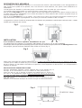
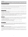
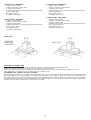
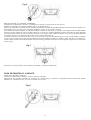
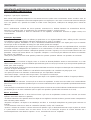
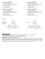
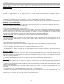
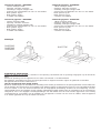
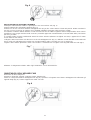
Depending on the model purchased, the hoods may be installed in the filtering or ducting version.
This model can be installed both in filtering or ducting versions, in accordance with your requirements.
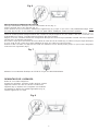
In the Filtering version (Fig. 1), the air and vapours conveyed by the appliance are depurated by charcoal filter and recirculated
around the room. ATTENTION: Using the hood as a filtering one it is necessary to use the charcoal filter that purifies the air
sent back into the room.
In the Ducting version (Fig. 2), cooking vapours and odours are conveyed straight outside by a disposal duct which passes
through the wall/ceiling. Use of charcoal filter is therefore unnecessary.
This apparatus conforms to the 16.08.89 regulation relating to the limitation of radio-electric disturbances (EC Directive n./
6.889 modified by the EC Directive 8/.308.).
INSTALLATION
It is advisable to entrust the installation operations to specialised personnel.
Read carefully the indications in the paragraph “IMPORTANT” at page 9 of the instruction booklet.
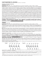
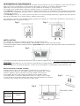
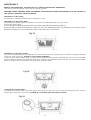
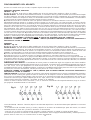
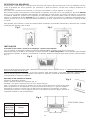
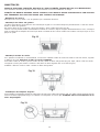
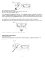
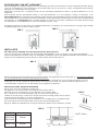
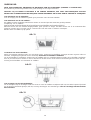
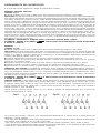
To facilitate installation, before starting remove the grease filters: press inward on the clamp at the handle and pull the filter
downward (Fig. 3).
Cut a hole in the bottom of the pensile cupboard in order to settle the appliance (Fig. 4). The pensile cupboard bottom must be
16 mm thick.
Check that the fixing tabs (Fig. 5) to the wall unit are positioned at a height suited to the thickness of the bottom of the wall
unit. If this distance is less than the thickness, increase it by unscrewing the 2 corresponding screws inside the hood.
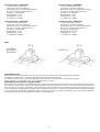
INSTALLATION IN FILTERING VERSION
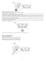
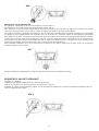
Install the wiring system. Insert the appliance in the hole (Fig. 4). Make the air
evacuation hole on the top of the pensile cupboard (Fig.1). Tighten the 2 screws
inside the appliance (Fig. 6) until it fits snug on the bottom of the wall unit.
Do not tighten the two screws strongly to maintain the two metallic clamps
in the right position. Connect the tube with the device air outlet, to such a height
to reach the top of the pensile cupboard (the tube is not included).Make the electrical
connection of the hood by means of the power supply cable.
Fig. 1
Fig. 2
Fig. 3
Fig. 4
Fig. 5
MODELS A
DHG556XP
DHG576XP
DHG589XP
DHG577XP
690mm
490mm
THICKNESS 16mm

11
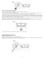
INSTALLATION OF THE DUCTING VERSIONS
Install the wiring system and prepare the air venting hole (Fig. 2).
Insert the appliance in the hole (Fig. 4).
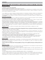
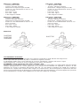
Tighten the 2 screws inside the appliance (Fig. 6) until it fits snug on the bottom of the wall unit. Do not tighten the two screws
strongly to maintain the two metallic clamps in the right position.
To get optimal conditions the air venting pipe should: be as short as possible, have the lowest number of bends (max bende angle:
90°), be made of material approved by local authorities (according to the State), have its inner side as regular and smooth as
possible. It is moreover recommended to avoid drastic changes of pipe cross section (recommended diameter: 150 mm). The
device is provided with a 150-125 cm reduction.
Connect the air exit tube with the device air outlet (Fig. 2): use a flexible tube and stop it in the device air outlet through a metallic
clamp (tube and clamp are not provided).
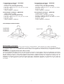
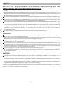
Remove the charcoal filter by placing pressure on the clamp located on the interior of the hood and rotating it until the two tabs
are removed from position (Fig. 7).
Make the electrical connection of the hood by means of the power supply cable.
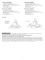
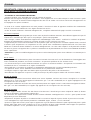
DEVICE DISASSEMBLY
Remove the grease filter.
During the following operations always support the device.
Tighten the 2 screws inside the device (Fig. 6); moving
the 2 small tongues toward the device inside using the
right carvings (Fig. 8); pull out the device from its side.
Fig. 6
Fig. 7
Fig. 8

12
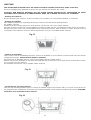
FUNCTIONING OF THE APPARATUS
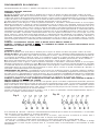
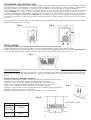
Depending on the model, the unit is equipped with the following controls:
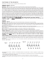
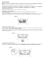
DHG556XP, DHG576XP, DHG577XP
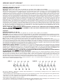
CONTROLS - Fig. 9:
A) ON/OFF - lamps. This button is also used for the alarm function of the grease and charcoal filters.
Filter alarm: After 30h of motor operation, the L1 LED comes ON and remains ON (the grease filters have to be cleaned). After
120h of motor operation, the L1 LED comes ON and flashes (the charcoal filter have to be changed if the hood is so equipped).
The Filter Alarm is ONLY given with the motor is OFF. The Filter Alarm is cancelled (HOUR meter reset) by holding down button
A for 2". B) Press button B to start the motor at Speed 1. The speed is shown by the L2 LED coming ON. When held down
for 2", the motor switches off. A single pressure on the button when the LED is ON activates the timer function (motor ON for
5'), shown by the flashing LED. To cancel the timer function, press the button again ONCE. C) Press button C to start the motor
at Speed 2. The speed is shown by the L3 LED coming ON. A single pressure on the button when the led is on activates the
timer function (motor on for 5'), shown by the flashing led. To cancel the timer function, press the button again ONCE. D) Press
button D to start the motor at Speed 3. The speed is shown by the L4 LED coming ON. A single pressure on the button when
the led is on activates the timer function (motor on for 5'), shown by the flashing led. To cancel the timer function, press the
button again ONCE. E) Press button E to start the il motor at Speed 4 (B = Booster). The speed is shown by the L5 LED coming
ON. A single pressure on the button when the led is on activates the timer function (motor on for 5'), shown by the flashing led.
To cancel the timer function, press the button again ONCE.
ATTENTION : BY ACTIVATING THE
TIMER FUNCTION, THE MOTOR SWITCHES OFF AFTER 5 MINUTES.
ATTENTION : WHEN THE
LED L1 LIGHTS UP IT IS TIME TO CLEAN THE GREASE FILTERS OR REPLACE THE
CHARCOAL FILTER.
DHG589XP
CONTROLS - Fig. 10:
A) ON/OFF - lamps. This button is also used for the alarm function of the grease and charcoal filters.
Filter alarm: After 30h of motor operation, the L1 LED comes ON and remains ON for 30" (the grease filters have to be cleaned).
After 120h of motor operation, the L1 LED comes ON and flashes for 30" (the charcoal filter have to be changed if the hood
is so equipped). The Filter Alarm is ONLY given with the motor is OFF. The Filter Alarm is cancelled (HOUR meter reset) by
holding down button A for 2".
B) The button B activates/deactivate sensor function (when activated the sensor is lit by the LED L2).
C) Press button C to start the motor at Speed 1. The speed is shown by the L3 LED coming ON. When held down for 2", the
motor switches off.
D) Press button D to start the motor at Speed 2. The speed is shown by the L4 LED coming ON.
E) Press button E to start the motor at Speed 3. The speed is shown by the L5 LED coming ON.
F) Press button F to start the il motor at Speed 4 (B = Booster). The speed is shown by the L6 LED coming ON.
SENSOR SENSITIVITY: sensitivity of the sensor may be modified in accordance with individual requirements. Modify the
sensitivity by pressing simultaneously on the A and B buttons. The set sensitivity level will be displayed via the 4 flashing Leds
- L3, L4, L5, and L6. The desired sensitivity is set via the C, D, E, and F buttons (C being minimum, F being maximum). Set
the sensitivity level to minimum for gas cook tops, medium for glass-ceramic cook tops and maximum for induction cook tops.
WARNING: WHEN
LED L1 LIGHTS UP, THIS INDICATES THAT THE GREASE OR CHARCOAL FILTERS REQUIRE
CLEANING.
FILTER SENSOR (activated via the B button): this device is equipped with a completely automatic system (Advanced Sensor
Control) for management of all hood functions. Thanks to the Advanced sensor Control (ASC), air circulating in the kitchen is
maintained clean and odour-free without requiring any user intervention. The sophisticated sensors are able to capture any type
of odour, vapour, smoke or heat caused by cooking. The ASC also captures any possible irregular gases present in the
environment.
When the sensor function is activated, the C, D, E and F buttons activate the speed temporarily, to then be overridden by the
automatic speed setting.
The 4th speed (B = Booster - intensive) is automatically lowered to 3rd speed after 5 minutes of operation to optimise energy
consumption.
- If the hood is left on (lights and/or motor), after 10 hours in the absence of commands from the user, it will automatically switch
to OFF condition with all services switched off.
- The Buzzer emits a “beep” each time that a command is set from the keyboard or remote control (optional).
- In the event of interruption of power during the hood, if you restore the hood in the OFF state, then the engine must be reactivate
manually.
Fig. 9
Fig. 10

13
Technical data - DHG556XP:
- 1 Motor - power 155W
- Voltage: 230-240V single phase
- 2 halogen lamps 20W
- Supplied with 150 cm electricity supply cable with plug.
- Gross weight: Kg.11
- Net weight: Kg.8,5
- 2 metallic grease filters
Technical data - DHG576XP:
- 1 Motor - power 250W
- Voltage: 230-240V single phase
- 2 halogen lamps 20W
- Supplied with 150 cm electricity supply cable with plug.
- Gross weight: Kg.11
- Net weight: Kg.8,5
- 2 metallic grease filters
Dimensions
Technical data - DHG589XP:
- 1 Motor - power 260W
- Voltage: 230-240V single phase
- 2 halogen lamps 20W
- Supplied with 150 cm electricity supply cable with plug.
- Gross weight: Kg.12
- Net weight: Kg.9,5
- 2 metallic grease filters
Technical data - DHG577XP:
- 1 Motor - power 250W
- Voltage: 230-240V single phase
- 2 halogen lamps 20W
- Supplied with 150 cm electricity supply cable with plug.
- Gross weight: Kg.13,5
- Net weight: Kg.10
- 2 metallic grease filters
ELECTRICITY CONNECTION
While connecting the electricity make sure that the tension is that indicated in the technical lable.
Before proceeding to cleaning or maintenance operations remove the tension.
Connecting the electricity must be performed by a specialised technician in conformity with the regulation in force.
This apparatus is constructed so as to belong to the I insulation class.
ATTENTION: This appliance must be grounded.
When making the electrical connections, check that the voltage values correspond to those indicated on the data plate inside
the appliance itself. In case your appliance is not fitted with a supply cord and a plug or with other means for disconnection from
the supply mains having a contact separation in all poles that provide full disconnection under overvoltage category III conditions,
that means for disconnection must be incorporated in the fixed wiring in accordance with the wiring rules. If your unit features
a power lead and plug, position this so the plug is accessible.
DHG556XP
DHG576XP
DHG589XP
DHG577XP

14
MAINTENANCE
REMOVE THE TENSION AT THE HOOD (PLUG or SWITCH) BEFORE ANY OPERATION-
Thorough servicing guarantees correct and long-lasting operation.
WARNING: MODEL DHG589XP HAVE THIS SENSOR. AVOID USING SILICON BASED PRODUCTS IN THE VICINITY OF
THE HOOD TO PREVENT SENSOR DAMAGE.
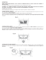
-Maintenance of the casing:
Avoid products containing abrasives when cleaning the casing.
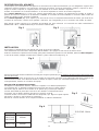
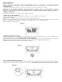
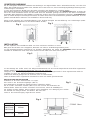
-Maintenance of the grease filters:
The grease filters require regular maintenance and must be cleaned periodically every two months.
Remove the grease filters:
In correspondence with the handle, push the stop inward and pull the filter downwards (Fig.11).
Wash them with a normal neutral product in commerce, then rinse abundantly and dry. The washing can be carried out in the
dishwasher making sure not to let the filters make contact with dirty or silver dishes.
-Maintenance of the charcoal filter:
If you are using the filtering version apparatus, the charcoal filter need to be changed every six months on average depending
on the use made of the hood. Reference charcoal filter: AH4063U1.
To take away the charcoal filter, firstly you must remove the grease filters (Fig.11). Following this, remove the charcoal filter
by placing pressure on the clamp located on the interior of the hood and rotating it until the two tabs are removed from position
(Fig. 12). Replace the charcooal filter and install again the grease filters.
-Changing the halogen lamps:
To replace the halogen bulbs, remove the grease filters (Fig. 11). Open the cover levering from the proper slots (Fig.13).
Change with a lamp of the same kind. CAUTION: Do not handle glass bulb with bare hands.
Fig. 11
Fig. 12
Fig. 13
Page is loading ...
Page is loading ...
Page is loading ...
Page is loading ...
Page is loading ...
Page is loading ...
Page is loading ...
Page is loading ...
Page is loading ...
Page is loading ...
Page is loading ...
Page is loading ...
Page is loading ...
Page is loading ...
Page is loading ...
Page is loading ...
Page is loading ...
Page is loading ...
Page is loading ...
Page is loading ...
Page is loading ...
Page is loading ...
Page is loading ...
Page is loading ...
Page is loading ...
Page is loading ...
Page is loading ...
Page is loading ...
Page is loading ...
Page is loading ...

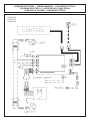
SCHÉMA ÉLECTRIQUE - WIRING DIAGRAM - ESQUEMA ELÉCTRICO
ESQUEMA ELÉCTRICO - ELEKTRISCHER SCHALTPLAN
ELEKTRISCH SCHEMA - SCHEMA ELETTRICO
DHG576XP
DHG577XP
DHG589XP

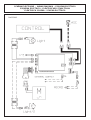
SCHÉMA ÉLECTRIQUE - WIRING DIAGRAM - ESQUEMA ELÉCTRICO
ESQUEMA ELÉCTRICO - ELEKTRISCHER SCHALTPLAN
ELEKTRISCH SCHEMA - SCHEMA ELETTRICO
DHG556XP
Page is loading ...

04307469/4
-
 1
1
-
 2
2
-
 3
3
-
 4
4
-
 5
5
-
 6
6
-
 7
7
-
 8
8
-
 9
9
-
 10
10
-
 11
11
-
 12
12
-
 13
13
-
 14
14
-
 15
15
-
 16
16
-
 17
17
-
 18
18
-
 19
19
-
 20
20
-
 21
21
-
 22
22
-
 23
23
-
 24
24
-
 25
25
-
 26
26
-
 27
27
-
 28
28
-
 29
29
-
 30
30
-
 31
31
-
 32
32
-
 33
33
-
 34
34
-
 35
35
-
 36
36
-
 37
37
-
 38
38
-
 39
39
-
 40
40
-
 41
41
-
 42
42
-
 43
43
-
 44
44
-
 45
45
-
 46
46
-
 47
47
-
 48
48


De Dietrich DHG556XP1 Owner's manual
- Category
- Cooker hoods
- Type
- Owner's manual
Ask a question and I''ll find the answer in the document
Finding information in a document is now easier with AI
in other languages
- italiano: De Dietrich DHG556XP1 Manuale del proprietario
- français: De Dietrich DHG556XP1 Le manuel du propriétaire
- español: De Dietrich DHG556XP1 El manual del propietario
- Deutsch: De Dietrich DHG556XP1 Bedienungsanleitung
- Nederlands: De Dietrich DHG556XP1 de handleiding
- português: De Dietrich DHG556XP1 Manual do proprietário
Related papers
-
De Dietrich DHG570XP1 Owner's manual
-
-
De Dietrich DHG570XP1 Owner's manual
-
 De Dietrich DHG370XP1 Owner's manual
-
 De Dietrich DHG690XP1 Owner's manual
-
De Dietrich DHD7561B Owner's manual
-
-
-
-


Other documents
-
ROSIERES RHT625RB Owner's manual
-
Zigmund & Shtain K 376.51 S User manual
-
Candy RBS 94 Owner's manual
-
EURO EP600SWSX Owner's manual
-
Candy CCR 616X User manual
-
-
-
-
Candy CMB 60 X User manual
-
Samsung HDC6C55TX User Instructions