Page is loading ...

CPC400 Series
User’s Guide
Watlow Controls
1241 Bundy Blvd.
Winona, MN 55987
Repairs and Returns:
334 Westridge Drive
Watsonville, CA 95076
Customer Service:
Phone.....1-800-414-4299
Fax .........1-800-445-8992
Technical Support:
Phone.....(507) 494-5656
Fax .........(507) 452-4507
Email ......wintechsupport@watlow.com
Part No. 0600-2900-2000 Rev. 2.2
August 2005

Copyright © 2005, Watlow Anafaze, Incorporated
Information in this manual is subject to change without notice. No part of this publi-
cation may be reproduced, stored in a retrieval system, or transmitted in any form
without written permission from Watlow Anafaze.
Anafaze is a registered trademark, and LogicPro is a trademark, of Watlow Electric
Manufacturing Company. Modbus is a trademark of Schneider Automation Incorpo-
rated. Windows is a registered trademark of Microsoft Corporation in the United
States and/or other countries. UL is a registered trademark of Underwriters Labora-
tories, Inc. All other trademarks are the property of their respective owners.
Warranty
Watlow Anafaze, Incorporated warrants that the products furnished under this Agree-
ment will be free from defects in material and workmanship for a period of three years
from the date of shipment. The Customer shall provide notice of any defect to Watlow
Anafaze, Incorporated within one week after the Customer's discovery of such defect.
The sole obligation and liability of Watlow Anafaze, Incorporated under this warranty
shall be to repair or replace, at its option and without cost to the Customer, the defec-
tive product or part.
Upon request by Watlow Anafaze, Incorporated, the product or part claimed to be
defective shall immediately be returned at the Customer's expense to Watlow Anafaze,
Incorporated. Replaced or repaired products or parts will be shipped to the Customer
at the expense of Watlow Anafaze, Incorporated.
There shall be no warranty or liability for any products or parts that have been sub-
ject to misuse, accident, negligence, failure of electric power or modification by the
Customer without the written approval of Watlow Anafaze, Incorporated. Final deter-
mination of warranty eligibility shall be made by Watlow Anafaze, Incorporated. If a
warranty claim is considered invalid for any reason, the Customer will be charged for
services performed and expenses incurred by Watlow Anafaze, Incorporated in han-
dling and shipping the returned unit.
If replacement parts are supplied or repairs made during the original warranty
period, the warranty period for the replacement or repaired part shall terminate with
the termination of the warranty period of the original product or part.
The foregoing warranty constitutes the sole liability of Watlow Anafaze, Incorporated
and the Customer's sole remedy with respect to the products. It is in lieu of all other
warranties, liabilities, and remedies. Except as thus provided, Watlow Anafaze, Inc.
disclaims all warranties, express or implied, including any warranty of merchantabil-
ity or fitness for a particular purpose.
Please Note: External safety devices must be used with this equipment.

Doc. 0600-2900-2000 Watlow Anafaze i
Table of Contents
List of Figures v
List of Tables ix
1 System Overview 1
Manual Contents 1
Getting Started 2
Product Features 2
CPC400 Parts List 4
Technical Description 6
Safety 9
2 Installation 11
Typical Installation 12
Mounting Controller Components 13
System Wiring 20
Power Connections 23
Testing the System 26
Sensor Wiring 27
Wiring Control and Digital I/O 32
Analog Outputs 39
Serial Communications 41
3 Operation and Setup 47
General Navigation Map 48
Keypad 49
Displays 50
Changing the Set Point 54
Changing the Control Mode and Output Power 55
Accessing and Navigating the Setup Menus 56
Setting Up Closed-Loop Control 57
Setting Up a Process or Pulse Input 58
Autotuning 62
Setting Up Alarms 63
Setting Up Process Variable Retransmit 67
Setting Up Cascade Control 69
Setting Up Ratio Control 73
Setting Up Differential Control 75

Table of Contents CPC400 Series User’s Guide
ii Watlow Anafaze Doc. 0600-2900-2000
Setting Up Remote Analog Set Point 76
Setting Parameters Through Serial Communications or a LogicPro Program 78
4 Tuning and Control 81
Control Algorithms 81
Manually Tuning PID Loops 85
Control Outputs 88
5 Menu and Parameter Reference 91
Operator Parameters 92
Overview of the Setup Menus 94
Global Setup Menu
96
Input Menu 104
Channel Menu 109
Control Menu 111
Output Menu 116
Alarms Menu 121
Process Variable Retransmit Menu 125
Cascade Menu 127
Ratio Menu 128
Soft Integers Menu 130
Soft Booleans Menu 131
I/O Tests Menu 131
Additional Parameters for Serial Communications and LogicPro Programs 132
6 Troubleshooting and Reconfiguring 139
When There is a Problem 139
Troubleshooting the Controller 140
Corrective and Diagnostic Procedures 145
Additional Troubleshooting for Computer Supervised Systems 152
Clearing the RAM 153
Replacing the Flash Memory Chip 154
Changing the Hardware Communications Protocol 157
Installing Scaling Resistors 157
Configuring Serial DAC Outputs 162
Configuring Dual DAC Outputs 163
7 Specifications 165
CPC400 System Specifications 165
CPC400 Power Supply 176
Dual DAC Specifications 178
Serial DAC Specifications 180
Appendix A: Modbus Protocol 183
Master-Slave Model 183
Modbus ASCII and RTU Modes 185
Message Framing 185
Error Checking Methods 188
Function Codes 190
Examples 193


Table of Contents CPC400 Series User’s Guide
iv Watlow Anafaze Doc. 0600-2900-2000

Doc. 0600-2900-2000 Watlow Anafaze v
List of Figures
1 System Overview 1
Figure 1.1—CPC400 Standard Parts List 5
Figure 1.2—CPC400 Special Inputs Parts List 6
Figure 1.3—CPC400 Rear Views 6
Figure 1.4—CPC400 Front Panel 7
Figure 1.5—TB50 8
2 Installation 11
Figure 2.1—CPC400 System Components 12
Figure 2.2—Clearance with Straight SCSI Cable (L) and Right-Angle SCSI Cable (R) 14
Figure 2.3—Wiring Clearances 14
Figure 2.4—Mounting Bracket 15
Figure 2.5—Mounting the TB50 16
Figure 2.6—TB50 Mounted on a DIN Rail (Front) 16
Figure 2.7—TB50 Mounted on DIN Rail (Side) 17
Figure 2.8—Mounting a TB50 with Standoffs 17
Figure 2.9—CPC400 Power Supply Mounting Bracket 18
Figure 2.10—Dual DAC and Serial DAC Dimensions 19
Figure 2.11—CPC400 Series Controller with TB18 23
Figure 2.12—CPC400 Series Controller with TB50 23
Figure 2.13—Power Connections with the CPC400 Power Supply 25
Figure 2.14—CPC400 Connector Locations 28
Figure 2.15—Thermocouple Connections 29
Figure 2.16—RTD Connections 29
Figure 2.17—Voltage Signal Connections 30
Figure 2.18—Current Signal Connections 30
Figure 2.19—Encoder with 5V
Î
(dc) TTL Signal 31
Figure 2.20—Encoder Input with Voltage Divider 31
Figure 2.21—Digital Output Wiring 33
Figure 2.22—Sample Heat, Cool and Alarm Output Connections 35
Figure 2.23—Output Connections Using External Power Supply 35
Figure 2.24—TB50 Watchdog Timer Output 35
Figure 2.25—TB18 Watchdog Timer Output 35
Figure 2.26—Wiring Digital Inputs 36
Figure 2.27—Dual DAC with Current Output 39
Figure 2.28—Dual DAC with Voltage Output 40
Figure 2.29—Single/Multiple Serial DACs 41

List of Figures CPC400 Series User’s Guide
vi Watlow Anafaze Doc. 0600-2900-2000
Figure 2.30—Connecting One CPC400 to a Computer Using EIA/TIA-232 42
Figure 2.31—Four-Wire EIA/TIA-485 Wiring 43
Figure 2.32—Two-Wire EIA/TIA-485 Wiring 43
Figure 2.33—Recommended System Connections 44
3 Operation and Setup 47
Figure 3.1—General Navigation Map 48
Figure 3.2—Keypad Navigation 49
Figure 3.3—Loop Display 50
Figure 3.4—Loop Display with Alarm Code 51
Figure 3.5—Display for Failed Sensor Alarm 51
Figure 3.6—Input Scaling 59
Figure 3.7—Activation and Deactivation of Process Alarms 66
Figure 3.8—Application Using Process Variable Retransmit 68
Figure 3.9—Secondary Set Point When Primary Loop Has Heat and Cool Outputs 70
Figure 3.10—Secondary Set Point When Primary Loop Has Heat Output Only 70
Figure 3.11—Example Application Using Cascade Control 72
Figure 3.12—Relationship of Secondary Loop Set Point to Primary Loop Process
Variable in Cascade Example 73
Figure 3.13—Relationship Between the Process Variable on the Master Loop and the
Set Point of the Ratio Loop 74
Figure 3.14—Application Using Ratio Control 75
4 Tuning and Control 81
Figure 4.1—On/Off Control 82
Figure 4.2—Proportional Control 83
Figure 4.3—Proportional and Integral Control 83
Figure 4.4—Proportional, Integral and Derivative Control 84
Figure 4.5—Time Proportioning and Distributed Zero Crossing Waveforms 88
5 Menu and Parameter Reference 91
Figure 5.1—Operator Parameter Navigation 92
Figure 5.2—Setup Menus and Parameters 95
Figure 5.3—The Effect of Tune Gain on Recovery from a Load Change 115
Figure 5.4—Linear and Nonlinear Outputs 121
6 Troubleshooting and Reconfiguring 139
Figure 6.1—Removal of Electronics Assembly from Case 155
Figure 6.2—Screw Locations on PC Board 155
Figure 6.3—Location of Flash Memory Chip 156
Figure 6.4—Removal of Flash Memory Chip 156
Figure 6.5—Jumper Configurations 157
Figure 6.6—Input Circuit 158
Figure 6.7—Serial DAC Voltage and Current Jumper Positions 162
Figure 6.8—Dual DAC 163

CPC400 Series User’s Guide List of Figures
Doc. 0600-2900-2000 Watlow Anafaze vii
7 Specifications 165
Figure 7.1—CPC400 Module Dimensions 166
Figure 7.2—CPC400 Clearances with Straight SCSI Cable 167
Figure 7.3—CPC400 Clearances with Right-Angle SCSI Cable 167
Figure 7.4—TB50 Dimensions 169
Figure 7.5—TB50 Dimensions with Straight SCSI Cable 170
Figure 7.6—TB50 Dimensions with Right-Angle SCSI Cable 171
Figure 7.7—Power Supply Dimensions (Bottom View) 177
Figure 7.8—Dual DAC Dimensions 179
Figure 7.9—Serial DAC Dimensions 181
Appendix A: Modbus Protocol 183
Figure A.1—Query - Response Cycle 184
Figure A.2—Example Message Frame 186

List of Figures CPC400 Series User’s Guide
viii Watlow Anafaze Doc. 0600-2900-2000

Doc.0600-2900-2000 Watlow Anafaze ix
List of Tables
2 Installation 11
Table 2.1—Cable Recommendations 21
Table 2.2—Power Connections 24
Table 2.3—Digital Output States and Values Stored in the Controller 33
Table 2.4—Digital Input States and Values Stored in the Controller 36
Table 2.5—TB18 Connections 37
Table 2.6—TB50 Connections 38
Table 2.7—EIA/TIA-232 Connections 42
Table 2.8—RTS/CTS and DSR/DTR Pins in DB-9 and DB-25 Connectors 42
3 Operation and Setup 47
Table 3.1—Control Modes on the Loop Display 50
Table 3.2—Alarm Codes and Messages for Process and Failed Sensor Alarms 52
Table 3.3—System Alarm Messages 53
Table 3.4—Input Readings 60
Table 3.5—Scaling Values 60
Table 3.6—Input Readings and Calculations 61
Table 3.7—Scaling Values 61
Table 3.8—Scaling Values 62
Table 3.9—Parameters Settings for Process Variable Retransmit Example 69
Table 3.10—Parameter Settings for the Primary Loop in the Cascade Example 72
Table 3.11—Parameter Settings for the Secondary Loop in the Cascade Example 72
Table 3.12—Ratio Control Settings for the Ratio Loop (Loop 2) in the Example 75
Table 3.13—Parameter Settings for the Ratio Loop (Loop 2) for the Example 76
Table 3.14—Parameters Settings for the Master Loop (Loop 1) in the Example 77
Table 3.15—Parameter Settings for the Ratio Loop (Loop 2) in the Example 78
Table 3.16—Number of Decimal Places for Numeric Values via Modbus or Logic 80
4 Tuning and Control 81
Table 4.1—Proportional Band Settings 85
Table 4.2—Integral Term and Reset Settings 86
Table 4.3—Derivative Term Versus Rate 86
Table 4.4—General PID Constants 87

List of Tables CPC400 Series User’s Guide
x Watlow Anafaze Doc. 0600-2900-2000
5 Menu and Parameter Reference 91
Table 5.1—Control Mode Menu Options 93
Table 5.2—CPC400 Setup Menus 94
Table 5.3—
Values for BCD Job Load
97
Table 5.4—Digital Input States Required to Load Each Job 98
Table 5.5—Power Up Loop Modes 100
Table 5.6—Digital Output Alarm Polarity 103
Table 5.7—Input Types and Ranges 104
Table 5.8—Calibration Offset Ranges 106
Table 5.9—Display Formats 107
Table 5.10—Characters for the Loop Name and Input Units Parameters 110
Table 5.11—PV Source Options 110
Table 5.12—Proportional Band Values 111
Table 5.13—Values for the Control Hysteresis and Deviation Alarm Parameters 113
Table 5.14— Control Types 115
Table 5.15—Heat and Cool Output Types 116
Table 5.16—Alarm Functions 122
Table 5.17—Values for Alarm Hysteresis 125
Table 5.18—Bit Positions for Alarm Enable and Alarm Function 133
Table 5.19—Bit Positions for Alarm Status and Alarm Acknowledge 134
Table 5.20—System Status Bits 137
6 Troubleshooting and Reconfiguring 139
Table 6.1—Operator Response to Process Alarms 142
Table 6.2—Other Symptoms 143
Table 6.3—Resistor Values for Current Inputs 159
Table 6.4—Resistor Locations for Current Inputs 159
Table 6.5—Resistor Values for Voltage Inputs 160
Table 6.6—Resistor Locations for Voltage Inputs 160
Table 6.7—Resistor Locations for RTD Inputs 161
Table 6.8—Dual DAC Jumper Settings 163
7 Specifications 165
Table 7.1—Agency Approvals / Compliance 165
Table 7.2—Environmental Specifications 165
Table 7.3—Physical Dimensions 166
Table 7.4—CPC400 with Straight SCSI 166
Table 7.5—CPC400 with Right Angle SCSI 167
Table 7.6—CPC400 Connections 168
Table 7.7—TB50 Physical Dimensions 168
Table 7.8—TB50 Connections 169
Table 7.9—TB50 with Straight SCSI 169
Table 7.10—TB50 with Right Angle SCSI 170
Table 7.11—Analog Inputs 172
Table 7.12—Pulse Inputs 172
Table 7.13—Programmable Logic 173
Table 7.14—Thermocouple Range and Resolution 173

CPC400 Series User’s Guide List of Tables
Doc. 0600-2900-2000 Watlow Anafaze xi
Table 7.15—RTD Range and Resolution 173
Table 7.16—Input Resistance for Voltage Inputs 174
Table 7.17—Digital Inputs 174
Table 7.18—Digital Outputs Control / Alarm 175
Table 7.19—CPU Watchdog Output 175
Table 7.20—5V
Î
(dc) Output (Power to Operate Solid-State Relays) 175
Table 7.21—CPC400 Serial Interface 176
Table 7.22—CPC400 Power 176
Table 7.23—Power Supply Environmental Specifications 176
Table 7.24—Power Supply Agency Approvals / Compliance 176
Table 7.25—Power Supply Physical Specifications 177
Table 7.26—Power Supply with Mounting Bracket 177
Table 7.27—Power Supply Inputs and Outputs 178
Table 7.28—Dual DAC Physical Specifications 178
Table 7.29—Dual DAC Power Requirements 179
Table 7.30—Dual DAC Specifications by Output Range 180
Table 7.31—Serial DAC Environmental Specifications 180
Table 7.32—Serial DAC Physical Specifications 180
Table 7.33—Serial DAC Agency Approvals / Compliance 181
Table 7.34—Serial DAC Inputs 181
Table 7.35—Serial DAC Power Requirements 182
Table 7.36—Serial DAC Analog Output
Specifications 182
Appendix A: Modbus Protocol 183
Table A.1—Function Codes 190
Table A.2—Diagnostics Subfunctions 191
Table A.3—Sample Packet for Host Query 193
Table A.4—Sample Packet for Slave Response 193
Table A.5—Sample Packet for Host Query 194
Table A.6—Sample Packet for Slave Response 194
Table A.7—Sample Packet for Host Query 194
Table A.8—Sample Packet for Slave Response 194

List of Tables CPC400 Series User’s Guide
xii Watlow Anafaze Doc. 0600-2900-2000

Doc. 0600-2900-2000 Watlow Anafaze 1
1
System Overview
Manual Contents
This manual describes how to install, set up, and operate a
CPC400 series controller. Each chapter covers a different as-
pect of your control system and may apply to different users:
•
Chapter 1: System Overview
provides a component
list and summary of features for the CPC400 series
controllers.
•
Chapter 2: Installation
provides detailed instruc-
tions on installing the CPC400 series controller and its
peripherals.
•
Chapter 3: Operation and Setup
provides instruc-
tions about operating and setting up the CPC400.
•
Chapter 4: Tuning and Control
describes available
control algorithms and suggestions for applications.
•
Chapter 5: Menu and Parameter Reference
pro-
vides detailed descriptions of all menus and parame-
ters for controller setup and for accessing parameter
and I/O values with a LogicPro program or via the se-
rial communications interface.
•
Chapter 6: Troubleshooting and Reconfiguring
includes troubleshooting, upgrading and reconfigur-
ing procedures for technical personnel.
•
Chapter 7: Specifications
lists detailed specifica-
tions of the controller and optional components.
•
Appendix: Modbus Reference
describes the Mod-
bus RTU communications protocol, which is used to
read and set parameter values through the serial com-
munications interface. This information is intended
for programmers writing software to communicate
with the CPC400.
•
Parameter Address Reference
provides a way to
quickly locate parameter addresses.

Chapter 1: System Overview CPC400 Series User’s Guide
2 Watlow Anafaze Doc. 0600-2900-2000
Getting Started
Safety Symbols
These symbols are used throughout this manual:
WARNING!
Indicates a potentially hazardous situation which,
if not avoided, could result in death or serious in-
jury.
CAUTION!
Indicates a potentially hazardous situation which,
if not avoided, could result in minor or moderate
injury or property damage.
NOTE!
Indicates pertinent information or an item that
may be useful to document or label for later refer-
ence.
Initial Inspection
Accessories may or may not be shipped in the same con-
tainer as the CPC400, depending upon their size. Check
the shipping invoice against the contents received in all
boxes.
Product Features
CPC400 series controllers offer high-performance closed-
loop control and user-programmable logic to manipulate
process control algorithms and sequential logic.
The CPC400 provides four or eight independent control
loops with analog inputs—thermocouples, RTDs and pro-
cess. An additional 2 kHz pulse loop is also provided.
When used as a stand-alone controller, you may operate
the CPC400 via the two-line 16-character display and
touch keypad. You can also use it as the key element in a
computer-supervised data acquisition and control system.
The CPC400 can be locally or remotely controlled via an
EIA/TIA-232 or EIA/TIA-485 serial communications inter-
face.
CPC400 features include:

CPC400 Series User’s Guide Chapter 1: System Overview
Doc. 0600-2900-2000 Watlow Anafaze 3
•
TRU-TUNE+™Adaptive Control
: Enable adaptive
control using the unique TRU-TUNE+™ adaptive al-
gorithm and optimize even difficult-to-control or dy-
namic processes. TRU-TUNE+™ monitors the process
variable and adjusts the control parameters automat-
ically to keep your process at set point and optimize for
set point and load changes.
•
User-Programmable Logic
: Customize the control-
ler to run custom closed-loop control algorithms or pro-
cesses. All closed-loop control parameters and system
I/O are available for user programs. Program and
closed-loop control variables can be shared or indepen-
dent. Use LogicPro software to write, monitor and de-
bug logic programs.
•
Direct Connection of Mixed Thermocouple Sen-
sors:
Connect most thermocouples to the controller
with no hardware modifications. Thermocouple inputs
feature reference junction compensation, lineariza-
tion, offset calibration to correct for sensor inaccura-
cies, detection of open, shorted or reversed
thermocouples, and a choice of Fahrenheit or Celsius
display.
•
Accepts Resistive Temperature Detectors
(RTDs):
Use three-wire, 100
Ω
, platinum, 0.00385-
curve sensors. Special inputs must be installed.
•
Automatic Scaling for Process Analog Inputs:
The CPC400 series automatically scales process in-
puts used with industrial process sensors. Enter two
points, and all input values are automatically scaled.
Special inputs must be installed.
•
Dual Outputs:
The CPC400 series includes both heat
and cool control outputs for each loop. Independent
control parameters are provided for each output.
•
Independently Selectable Control and Output
Modes:
Set each control output to on/off, time propor-
tioning, Serial DAC (digital-to-analog converter) or
distributed zero crossing mode. Set up to two outputs
per loop for on/off, P, PI or PID control with reverse or
direct action.
•
Boost Output Function:
Set digital outputs to func-
tion as boost on/off control in association with any
alarm.
•
Flexible Alarms:
Independently set high and low
alarms and high and low deviation alarms for each
loop. Alarms can activate a digital output by them-
selves, or they can be grouped with other alarms to ac-
tivate an output.
•
Global Alarm Output:
Any alarm event activates
the global alarm output.
•
CPU Watchdog:
The CPU watchdog timer output no-
tifies you of system failure.

Chapter 1: System Overview CPC400 Series User’s Guide
4 Watlow Anafaze Doc. 0600-2900-2000
•
Keypad or Computer Operation:
Set up and run
the controller from the keypad or from a local or re-
mote computer. Use WATVIEW HMI software to set
up the controller, manage jobs (recipes), log data or
monitor system performance.
•
Modbus RTU Protocol, EIA/TIA-232 and 485
Communications:
Connect operator interface termi-
nals and third-party software packages using the
widely supported Modbus RTU protocol.
•
Multiple Job Storage:
Store up to eight jobs in the
controller’s battery-backed memory. Load a job
through the keypad, digital inputs or software. Each
job is a set of operating conditions, including set points
and alarm limits.
•
Nonlinear Output Curves:
Select either of two non-
linear output curves for each control output.
•
Pulse Input:
Use the pulse input for precise control of
motor or belt speed.
•
Low Power Shutdown:
The controller shuts down
and turns off all outputs when it detects the input volt-
age drop below the minimum safe operating level.
•
Process Variable Retransmit:
Scale a temperature
or process and convert it to an analog output for exter-
nal devices such as chart recorders.
•
Two-Zone Cascade Control:
Control thermal sys-
tems with long lag times, which cannot be accurately
controlled with a single loop.
•
Ratio or Offset Control:
Control one process as a ra-
tio or offset of another process.
•
Remote Analog Set Point:
Scale an external voltage
or current source to provide a set point for a loop.
CPC400 Parts List
You may have received one or more of the following compo-
nents. See
Figure 2.1 on page 12
for CPC400 configuration
information.
• CPC400 series controller
• Controller mounting kit
• TB50 with 50-pin SCSI cable
• EIA/TIA-232 or EIA/TIA-485 communications cable
• Power supply with mounting bracket and screws
• Serial DAC (digital-to-analog converter)
• Special input resistors (installed in CPC400)
• User’s guide

CPC400 Series User’s Guide Chapter 1: System Overview
Doc. 0600-2900-2000 Watlow Anafaze 5
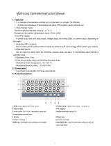
Figure 1.1 CPC400 Standard Parts List
40 _ -1 _ _ _ _ _ _
Number of Loops
4 = 4 loops
8 = 8 loops
Controller Type
1 = Standard firmware
Terminal Block
0 = No terminal block accessory
1 = 18-terminal block
2 = 50-terminal block, includes 3-foot (0.9 m) 50-pin SCSI cable (TB50-SCSI)
Power Supply
0 = No power supply
2 = 120/240V
Å (ac), 50/60 Hz power supply adapter
(5V
Î [dc] @ 4 A, 15VÎ [dc] @ 1.2 A), CE approved
SCSI Cables (for use with TB50-SCSI)
0 = No special SCSI cable (3-foot [0.9 m] cable is included with 50-terminal block)
1 = 6-foot (1.8 m) SCSI cable (CA-SCSI-6)
2 = 3-foot (0.9 m) right-angle SCSI cable (CA-SCSI-RT-3)
3 = 6-foot (1.8 m) right-angle SCSI cable (CA-SCSI-RT-6)
Serial Cables (for communications with computer)
0 = No serial communications cable
1 = 10-foot (3.0 m) serial cable, DB-9 female/bare wire (CA-COMM-010)
2 = 25-foot (7.6 m) serial cable, DB-9 female/bare wire (CA-COMM-025)
3 = 50-foot (15.2 m) serial cable, DB-9 female/bare wire (CA-COMM-050)
Serial Communications Jumper Settings
0 = EIA/TIA-232
1 = EIA/TIA-485
2 = EIA/TIA-485 terminated
Special Inputs
Standard unit is configured for thermocouples and -10 to +60mV process inputs.
For other sensors, special inputs are required.
0 = Thermocouples and -10 to +60mV inputs only
X = Number of current and voltage inputs.

Chapter 1: System Overview CPC400 Series User’s Guide
6 Watlow Anafaze Doc. 0600-2900-2000
Figure 1.2 CPC400 Special Inputs Parts List
Technical Description
This section contains a technical description of each compo-
nent of the CPC400 series controller.
CPC400
The CPC400 is housed in a 1/8-DIN panel mount package.
It contains the central processing unit (CPU), random ac-
cess memory (RAM) with a built-in battery, flash memory,
serial communications, digital I/O, analog inputs, display
and touch keypad.
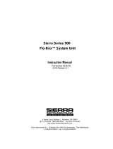
Figure 1.3 CPC400 Rear Views
CPCSI _ _ - _ _ - _ _
Special/Process Input Type
(Not required for thermocouple sensor inputs)
23 = RTD
43 = 0 to 10 mA
Î (dc)
44 = 0 to 20 mA
Î (dc) or 4 to 20 mAÎ (dc)
50 = 0 to 100 mV
Î (dc)
52 = 0 to 500 mV
Î (dc)
53 = 0 to 1 V
Î (dc)
55 = 0 to 5 V
Î (dc)
56 = 0 to 10 V
Î (dc)
57 = 0 to 12 V
Î (dc)
Start Loop
XX = Loop number XX
End Loop
XX = Loop number XX
CPC400 Series
with SCSI Connector
CPC400 Series
with TB18 Connector
/