Honeywell T7351F2010 Operating instructions
- Category
- Thermostats
- Type
- Operating instructions
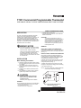
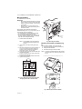
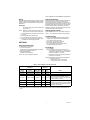
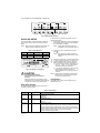
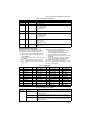
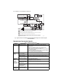
Honeywell T7351F2010 is a programmable thermostat designed to control heating and cooling systems in commercial buildings. It features a large, easy-to-read display and a simple, intuitive interface. The T7351F2010 can be programmed to automatically adjust the temperature throughout the day, ensuring a comfortable environment while saving energy. It also has a number of other features, including:
- 7-day programming: Allows you to set different temperatures for different times of day and days of the week.
- Temporary override: Lets you temporarily override the programmed schedule without affecting the permanent settings.


-
 1
1
-
 2
2
-
 3
3
-
 4
4
-
 5
5
-
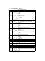 6
6
-
 7
7
-
 8
8
-
 9
9
-
 10
10
-
 11
11
-
 12
12
-
 13
13
-
 14
14
-
 15
15
-
 16
16


Honeywell T7351F2010 Operating instructions
- Category
- Thermostats
- Type
- Operating instructions
Honeywell T7351F2010 is a programmable thermostat designed to control heating and cooling systems in commercial buildings. It features a large, easy-to-read display and a simple, intuitive interface. The T7351F2010 can be programmed to automatically adjust the temperature throughout the day, ensuring a comfortable environment while saving energy. It also has a number of other features, including:
- 7-day programming: Allows you to set different temperatures for different times of day and days of the week.
- Temporary override: Lets you temporarily override the programmed schedule without affecting the permanent settings.
Ask a question and I''ll find the answer in the document
Finding information in a document is now easier with AI
Related papers
-
Honeywell T7351 User manual
-
-
-
-
Honeywell PROGRAMMABLE THERMOSTAT User manual
-
-
-
-
-
Other documents
-
Bryant P User manual
-
-
-
Carrier 50QE900-220LA User manual
-
-
-
Robertshaw 300-204 Owner's manual
-
-
-
American Standard TCONT401AN21MA Comfort Control Installer's Manual