5
GENERAL INFORMATION
The P5RD packaged air conditioner is designed only
for outdoor ground level installations and can be readily
connected to the high static duct system of a home. This unit
has been tested for capacity and effi ciency in accordance
with A.R.I. Standards and will provide many years of safe
and dependable comfort, providing it is properly installed
and maintained. Abuse, improper use, and/or improper
maintenance can shorten the life of the appliance and
create unsafe hazards.
To achieve optimum performance and minimize equipment
failure, it is recommended that periodic maintenance be
performed on this unit. The ability to properly perform
maintenance on this equipment requires certain
mechanical skills and tools.
Before You Install this Unit
The cooling load of the area to be conditioned must be
calculated and a system of the proper capacity selected.
It is recommended that the area to be conditioned be
completely insulated and vapor sealed.
Check the electrical supply and verify the power supply
is adequate for unit operation. If there is any question
concerning the power supply, contact the local power
company.
All units are securely packed at the time of shipment and
upon arrival should be carefully inspected for damage
prior to installing the equipment at the job site. Verify
coil fi ns are straight. If necessary, comb fi ns to remove
fl attened or bent fi ns. Claims for damage (apparent or
concealed) should be fi led immediately with the carrier.
Please consult your dealer for maintenance information
and availability of maintenance contracts. Please read
all instructions before installing the unit.
Locating the Air Conditioner
• Survey the job site to determine the best location for
mounting the outdoor unit. Select a solid, level position,
preferably on a concrete slab, slightly above the grade
level, and parallel to the home. If possible, select a site
for the unit that is as close as possible to the proposed
return grille location. DO NOT PLACE UNIT UNDER
THE HOME.
• The unit should be located with consideration of
minimizing the length of the supply and return ducts.
If practical, place the air conditioner and its ducts in
an area where they will be shaded from the afternoon
sun, when the heat load is greatest.
• The length of the supply and return ducts should be
kept to a minimum with no sharp radius bends.
• Overhead obstructions, poorly ventilated areas, and
areas subject to accumulation of debris should be
avoided. The hot condenser air must be discharged
up and away from the home, and if possible, in a
direction with the prevailing wind. Do not place the unit
in a confi ned space. See Figure 10 (page 13) for unit
dimensions.
• Suffi cient clearance for unobstructed airfl ow through
the outdoor coil must be maintained in order to achieve
rated performance.
• Consideration should also be given to availability of
electric power, service access, noise, and shade.
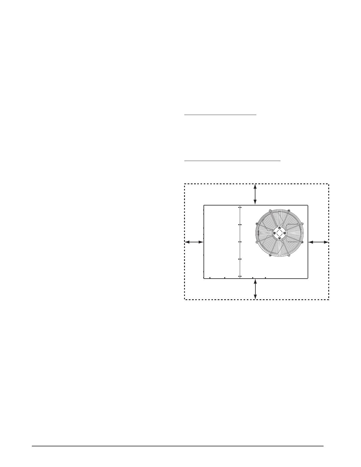
Minimum Clearance Requirements
Suffi cient clearance for unobstructed airfl ow through the
outdoor coil must be maintained in order to provide room
for proper servicing and achieve rated performance. See
Figure 2 for minimum clearances to obstructions.
Service Access Clearances
Blower access panel side ..........................................24”
Electrical compartment access panel side ................12”
Clearance between overhang & top of unit ................72”
Clearance around condenser coil area to wall or
shrubs (excludes duct panel side) .............................12”
Clearances to Combustible Materials
Supply and return air ducts .........................................0”
Duct connection side ...................................................0”
12"
12"
24"
TOP OF UNIT
TO BE
UNOBSTRUCTED
0"
Figure 2. Minimum Unit Clearances
Air Duct System
Air ducts must be installed in accordance with the standards
of the National Fire Protection Association “Standard for
Installation of Air Conditioning and Ventilation Systems”
(NFPA 90A), “Standard for Installation of Residence Type
Warm Air Heating and Air Conditioning Systems” (NFPA
90B), these instructions, and all applicable codes. NFPA
publications are available by writing to: National Fire
Protection Association, Batterymarch Park, Quincy, ME
02269 or visit www.NFPA.org on the web.
• Design the duct work according to methods described
by the Air Conditioning Contractors of America (ACCA).
• The supply duct system, including the number and
type of registers, will have much more effect on the
performance of the system than any other factor. The
duct must be suffi ciently large to conduct an adequate
amount of air to each register. See Figure 3 (page 6).


