13
Advanced Wireless-N Router
Linksys E2100L Chapter 3: Advanced Configuration
Username and Password Enter the Username and
Password provided by your ISP.
Connect on Demand: Max Idle Time You can configure
the Router to cut the Internet connection after it has
been inactive for a specified period of time (Max Idle
Time). If your Internet connection has been terminated
due to inactivity, Connect on Demand enables the Router
to automatically re-establish your connection as soon
as you attempt to access the Internet again. To use this
option, select Connect on Demand. In the Max Idle Time
field, enter the number of minutes you want to elapse
before your Internet connection terminates. The default is
5 minutes.
Keep Alive: Redial Period If you select this option, the
Router will periodically check your Internet connection. If
you are disconnected, then the Router will automatically
re-establish your connection. To use this option, select
Keep Alive. In the Redial Period field, specify how often
the Router should check the Internet connection. The
default is 30 seconds.
L2TP
Layer 2 Tunneling Protocol (L2TP) is a service that applies
to connections in Israel only.
Internet Connection Type > L2TP
Server IP Address This is the IP address of the L2TP
Server. Your ISP will provide you with the IP Address you
need to specify here.
Username and Password Enter the Username and
Password provided by your ISP.
Connect on Demand: Max Idle Time You can configure
the Router to cut the Internet connection after it has
been inactive for a specified period of time (Max Idle
Time). If your Internet connection has been terminated
due to inactivity, Connect on Demand enables the Router
to automatically re-establish your connection as soon
as you attempt to access the Internet again. To use this
option, select Connect on Demand. In the Max Idle Time
field, enter the number of minutes you want to elapse
before your Internet connection terminates. The default is
5 minutes.
Keep Alive: Redial Period If you select this option, the
Router will periodically check your Internet connection. If
you are disconnected, then the Router will automatically
re-establish your connection. To use this option, select
Keep Alive. In the Redial Period field, specify how often
the Router should check the Internet connection. The
default is 30 seconds.
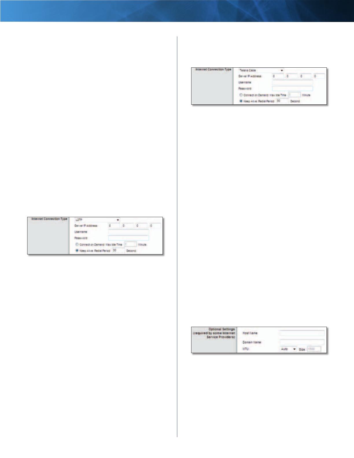
Telstra Cable
Telstra Cable is a service that applies to connections in
Australia only.
Internet Connection Type > Telstra Cable
Server IP Address This is the IP address of the Telstra
Cable. Your ISP will provide you with the IP Address you
need to specify here.
Username and Password Enter the Username and
Password provided by your ISP.
Connect on Demand: Max Idle Time You can configure
the Router to cut the Internet connection after it has
been inactive for a specified period of time (Max Idle
Time). If your Internet connection has been terminated
due to inactivity, Connect on Demand enables the Router
to automatically re-establish your connection as soon
as you attempt to access the Internet again. To use this
option, select Connect on Demand. In the Max Idle Time
field, enter the number of minutes you want to elapse
before your Internet connection terminates. The default is
5 minutes.
Keep Alive: Redial Period If you select this option, the
Router will periodically check your Internet connection. If
you are disconnected, then the Router will automatically
re-establish your connection. To use this option, select
Keep Alive. In the Redial Period field, specify how often
the Router should check the Internet connection. The
default is 30 seconds.
Optional Settings
Some of these settings may be required by your ISP. Verify
with your ISP before making any changes.
Optional Settings
Host Name and Domain Name These fields allow you to
supply a host and domain name for the Router. Some ISPs,
usually cable ISPs, require these names as identification.
You may have to check with your ISP to see if your
broadband Internet service has been configured with a
host and domain name. In most cases, leaving these fields
blank will work.
MTU MTU is the Maximum Transmission Unit. It specifies
the largest packet size permitted for Internet transmission.


