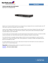
1X8

IBM 1X8 User manual

  • Hello! I am an AI chatbot trained to assist you with the IBM 1X8 User manual. I’ve already reviewed the document and can help you find the information you need or explain it in simple terms. Just ask your questions, and providing more details will help me assist you more effectively!
No solution built with IBM Server® xSeries® servers is complete until
the products are brought together using the right KVM switching options.
KVM switching solutions provide access and control of multiple servers
from a central console. These switches eliminate extra keyboards, monitors
and mice, allowing businesses to save critical space in their data centers.
IBM console switch solutions are designed to accommodate the full line of
xSeries server products, providing centralized control and management of
rack-optimized servers.
IBM now offers a new family of KVM switches. The Global Console
Manager appliances offer a choice of either the 2x16 (GCM2) or 4x16
(GCM4) for remote and local access. Additionally, there is the Local 2x8
Console Manager (LCM2) as well as the 1x8 Console Switch and the
2x16 Console Switch for local connectivity. They are all designed to offer
flexibility and scalability in managing a data center environment, as well as
dramatically reducing cable clutter at the rack.
Compelling reasons to buy a KVM solution from IBM:
IBM KVM products have an intuitive graphical user interface (GUI)
that makes switching between connected systems simple and easy.
IBM KVM products have been tested by IBM under the IBM
ServerProven® program and approved for operation with xSeries
servers, helping speed deployment while maximizing manageability
and control.
As with all IBM KVM products, these KVM options are backed by
acclaimed IBM service and support and include a three-year limited
warranty** when installed in an IBM rack or used with IBM servers.
Global Console Manager
Local Console Manager
1X8 Console Switch
2X16 Console Switch
IBM CONSOLE SWITCH
Decision Maker’s Guide
Contents
Global Console Manager 2
Key features and benefits 3
Basic GCM configuration 4
Technical Specifications 5
Local Console Manager 6
Key features and benefits 6
Basic LCM2 configuration 7
Technical Specifications 8
1x8 Console Switch &
2x16 Console Switch 9
Key features and benefits 10
Basic Console Switch configuration 11
Technical Specifications 12
Selecting the right IBM KVM solution 13
Frequently Asked Questions 14
For more information 18
Last updated October 2005 1
Global Console Manager
The IBM® Global 2 x 16 Console Managers (GCM2) and the IBM Global 4x16 Console
Manager (GCM4) appliances integrate digital and analog keyboard, video, and mouse
(KVM) switching technology with advanced cable management, access for three (2
remote, 1 local) or four (3 remote, 1 local or 4 remote) simultaneous users, and an intui-
tive graphical user interface. The appliances have USB and PS/2® ports on the rear
panel that support all major target device platforms.
The appliance is a rack mountable KVM switch, configurable for analog (local) or digital
(remote) connectivity. Video resolutions are supported up to 1280 x 1024 for remote users.
The GCM2 appliance includes two digital access sets for KVM-over-IP, 1 analog port
set for KVM connections, 16 analog rack interface (ARI) ports for connecting CO cables
and target devices, and virtual media capability for one local user and up to two remote
users. The GCM4 appliance includes four digital access sets for KVM-over-IP, 1 analog
port set for KVM connections, 16 ARI ports for connecting CO cables and target devices,
and virtual media capability for one local user and up to four remote users.
The appliance has user peripheral ports for PS/2® and USB keyboards and mice.
Additionally, virtual media such as generic removable media and CD drives can be
connected to any one of four USB ports. The appliance works over standard LAN
connections. Users can access target devices across a 1000BASE-T LAN port that is
used to establish an Ethernet connection, or directly through a local port. The IP-based
appliance gives you target device control from ANYWHERE in the world.
You can use the following Conversion Option (CO) cables with the appliance.
IBM 250 mm KVM Conversion Option (KCO) - PS/2 and VGA connectors
IBM 1.5 M KVM Conversion Option (KCO) - PS/2 and VGA connectors
IBM Virtual Media Conversion Option (VCO) - USB2 and VGA connectors,
required for virtual media connections—does not support chaining
IBM USB Conversion Option (UCO) - USB and VGA connectors
These intelligent CO cables with Cat5 design dramatically reduce cable clutter while
providing optimal digital display resolution and video settings. The built-in memory of the
CO cable simplifies configuration by assigning and retaining unique target device identi-
fication codes for each attached target device. This integrated intelligence enhances
security and prevents unauthorized access to a target device through cable manipula-
tion. The CO cable is turned on directly from the target device and provides Keep Alive
functionality when the appliance is not turned on. The CO cables enable local and remote
KVM connectivity to target devices that are attached to the appliance. Each appliance
has 16 ARI ports for connecting CO cables.
Ordering information:
IBM 2x16 Global Console Manager MTMN: 17352GX
IBM 4x16 Global Console Manager MTMN: 17354GX
Cable options:
IBM Short KVM Conversion Option (KCO) Part #: 39M2896
IBM Long KVM Conversion Option (KCO) Part #: 39M2897
IBM Virtual Media Conversion Option (VCO) Part #: 39M2894
IBM USB Conversion Option (UCO) Part #: 39M2895
KCO
UCO
Products and Solutions
Last updated October 2005 2
VCO
Virtual Media
The appliance supports virtual media when connected to a VCO cable. You can use virtual
media support to connect USB media devices to the appliance and make those devices
available to any connected GCM2 or GCM4 appliance. Use virtual media to move data
between a target device and USB media devices that are connected to the appliance. You
can install, upgrade, or recover the operating system; update the BIOS code; or start the
target device from a USB drive through the virtual media capabilities of the appliance.
Virtual media can be connected directly to the appliance using one of four USB ports on
the appliance. In addition, virtual media can be connected to any remote workstation that
is running IBM Virtual Console Software (VCS) and is connected to the appliance using
an Ethernet connection. To open a virtual media session with a target device, the target
device must first be connected to the appliance using a VCO cable.
Chaining Technology
IBM’s unique cable chaining solution enables users to manage a “daisy chainof multiple
servers through a single connection to a console or KVM switch, replacing many long
cables with just a few short ones, simplifying rack management, helping lower cabling
cost and reducing setup, diagnostic, and maintenance times. The “daisy chain” connec-
tivity has the added advantage of thin, flexible industry-standard CAT5 cabling and
standard RJ-45 connectors removing the need for one-to-one, dedicated cable connec-
tions between KVM switch ports and managed devices. This cable chaining solution
allows up to 16 KCOs or UCOs to be chained together.
OSCAR® graphical user interface
The appliance uses the OSCAR interface, which has menus to configure the switching
system and select computers. You can list target devices by unique name, eID (electronic
ID), or port number. Use the OSCAR interface to protect the switching system with a
screen saver password. After a user-defined time, the screen saver mode engages and
access is prohibited until the correct password is entered to reactivate the switching
system.
Flash upgradability
Upgrade the appliance at any time through the network port to ensure the appliance is
always running the most current available version.
Accessing the appliance through network connection
Users access the appliance and all attached target devices through Ethernet from a client
computer. A client computer can be anywhere a valid network connection exists.
Accessing target devices
When you access the VCS, a listing of all target devices you have permission to view and
manage opens. When you select a target device from the list, the video of the selected
target device opens in a Video Viewer window.
Key features and benefits
Last updated October 2005 3
Included with each part number:
Console Switch
Power cord
One serial cable
Rack-mounting brackets
Documentation CD
Virtual Console Software CD
Quick Installation Guide
1-U filler panel
16 terminators
Additional items needed:
One KCO, UCO, or VCO cable per attached
target device or appliance
One CAT5 patch cable per attached target
device or appliance
One Phillips screwdriver
Basic GCM configuration
Last updated October 2005 4
Technical Specifications
Last updated October 2005 5
Target device Ports
Number 16
Types VCO, KCO, and UCO
Connectors RJ-45
Sync Types Separate horizontal and vertical
Plug and Play DDC2B
Video Resolution 640 x 480 @ 60 Hz (Local Port and Remote Port Minimum)
800 x 600 @ 75 Hz
960 x 700 @ 75 Hz
1024 x 768 @ 75 Hz
1280 x 1024 @ 75 Hz (Remote Port Maximum using a VCO)
Supported Cabling 4-pair UTP Cat5 or Cat6, 10 meters maximum length
Serial Port
Number 1
Cable type Serial RS-232
Connector DB9 female
Network Connection
Number 1
Type Ethernet: IEEE 802.3 2002 Edition - 10BASE-T, 100BASE-T, 1000BASET
Connector RJ-45
Local Port
Number 1
Type USB, PS/2, and VGA
Connectors PS/2 miniDIN, 15 pin D, RJ-45
USB Device Port
Number 4
Type USB 2.0
Dimensions
Height x Width x Depth 1.72 in. x 17.00 in. x 10.98 in.; 1-U form factor
(4.37 cm x 43.18 cm x 27.98 cm)
Weight 7.3 lbs (3.31 kg) without cables
Power Supply
Heat dissipation 92 BTU/Hr
Airflow 8 CFM
Power consumption 12.5 Watts
AC-input power 40 Watts maximum
AC-input voltage rate 100 to 240 V ac Autosensing
AC-input current rating 0.5 A
AC-input cable 18 AWG three-wire cable, with a three-lead IEC-320 receptacle on the power
supply end and a country-dependent connector on the power resource end
AC frequency 50 to 60 Hz Autosensing
Ambient atmospheric condition ratings
Temperature to 50° Celsius (32° to 122° Fahrenheit) operating
-20° to 60° Celsius (-4° to 140° Fahrenheit) nonoperating
Humidity 20 to 80% noncondensing operating
5 to 95% noncondensing nonoperating
Safety and EMC approvals and markings
UL, FCC, cUL, ICES, CE, N, GS, IRAM, GOST, VCCI, MIC, C-Tick
Last updated October 2005 6
The IBM® Local 2x8 Console Manager (LCM2) appliance integrates analog keyboard,
video, and mouse (KVM) switching technology with advanced cable management and
access for two local simultaneous users. On-screen management through the OSCAR®
for IBM graphical user interface provides easy system configuration and target device
selection. The LCM2 appliance has USB and PS/2® ports on the rear panel that support all
major target device platforms.
The LCM2 uses the same CO cables as the GCM (please see GCM section for more infor-
mation). The CO cables enable direct KVM connectivity to target devices that are attached
to the appliance. Each LCM2 appliance has eight analog rack interface (ARI) ports for
connecting CO cables. The CO cables that work with the LCM2 appliance support target
devices with PS/2 and USB ports. When using the OSCAR interface in conjunction with CO
cables, you can easily switch between platforms.
Ordering information:
IBM 2x8 Local Console Manager MTMN: 17351GX
Cable options:
IBM Short KVM Conversion Option (KCO) Part #: 39M2896
IBM Long KVM Conversion Option (KCO) Part #: 39M2897
IBM Virtual Media Conversion Option (VCO) Part #: 39M2894
IBM USB Conversion Option (UCO) Part #: 39M2895
Virtual Media
The LCM2 appliance supports virtual media when connected to a VCO cable. You can use
virtual media support to connect USB media devices to the appliance and make those
devices available to any connected LCM2 appliance. Use virtual media to move data
between a target device and a USB media device that are connected to the appliance. You
can install, upgrade, or recover the operating system; update the BIOS code; or start the
target device from a USB drive through the virtual media capabilities of the LCM2 appli-
ance. To open a virtual media session with a target device, the target device must first be
connected to the appliance using a VCO cable.
Chaining Technology
IBM’s unique cable chaining solution enables users to manage a “daisy chain” of multiple
servers through a single connection to a console or KVM switch, replacing many long
cables with just a few short ones, simplifying rack management, helping lower cabling cost
and reducing setup, diagnostic, and maintenance times. The “daisy chain” connectivity
has the added advantage of thin, flexible industry-standard CAT5 cabling and standard RJ-
45 connectors removing the need for one-to-one, dedicated cable connections between
KVM switch ports and managed devices. This cable chaining solution allows up to 16 KCOs
or UCOs to be chained together.
OSCAR graphical user interface
The LCM2 appliance uses the OSCAR interface, which has menus to configure the switching
system and select computers. You can list target devices by unique name, eID (electronic
ID), or port number. Use the OSCAR interface to protect the switching system with a screen
saver password. After a user-defined time, the screen saver mode engages and access is
prohibited until the correct password is entered to reactivate the switching system.
Flash upgradability
Upgrade the LCM2 appliance at any time through the network port to ensure the appliance
is always running the most current available version.
Tiering expansion
The LCM2 appliance features an analog console interface (ACI) port that you can use to
tier between appliances using only a Cat5 cable. The LCM2 appliance allows for three
levels of tiering. You can connect a maximum of 512 target devices with three tiers of
LCM2 appliances.
Local Console Manager 2
Key features and benefits
Included with each part number:
Console Switch
Power cord
One serial cable
Rack-mounting brackets
Documentation CD
Quick Installation Guide
1-U filler panel
Eight terminators
Additional items needed:
One KCO, UCO, or VCO cable per attached
target device or appliance
One CAT5 patch cable per attached target
device or appliance
One Phillips screwdriver
Last updated October 2005 7
Basic LCM2 configuration
Last updated October 2005 8
Technical Specifications
Target device ports
Number 8
Cable types VCO, KCO, and UCO
Connectors RJ-45
Sync types Separate horizontal and vertical
Plug and Play DDC2B
Video resolution Local Port Maximum 1280 x 1024 @ 75 Hz
Serial port
Number 1
Type Serial RS-232
Connector DB9 female
Analog port sets
Number 2
Type PS/2, USB, VGA, and ACI
Connectors PS/2 miniDIN, 15 pin D, RJ-45
Dimensions
Height x Width x Depth 4.37 cm x 43.18 cm x 20.32 cm; 1-U form factor
(1.72 in. x 17.00 in. x 8.00 in.)
Weight 2.6 kg (5.75 lb) without cables
Power supply
Heat dissipation 92 BTU/Hr
Airflow 8 CFM
Power consumption 12.5 Watts
AC-input power 40 Watt maximum
AC-input voltage rating 100 to 240 V ac Autosensing
AC-input current rating 0.5 A
AC-input cable 18 AWG three-wire cable, with a three-lead IEC-320 receptacle on the power
supply end and a country or region dependent connector on the power
resource end
AC-frequency 50 to 60 HZ
Ambient atmospheric condition ratings
Temperature to 50° Celsius (32° to 122° Fahrenheit) operating
-20° to 60° Celsius (-4° to 140° Fahrenheit) nonoperating
Humidity 20 to 80% noncondensing operating
5 to 95% noncondensing nonoperating
Safety and EMC approvals and markings
UL, FCC, cUL, ICES, CE, N, GS, IRAM, GOST, VCCI, MIC, C-Tick
Last updated October 2005 9
The IBM 1x8 Console Switch and the IBM 2x16 Console Switch integrate keyboard, video,
and mouse (KVM) switching technology with advanced cable management, flexible
access for up to two simultaneous users, and an intuitive user interface. The console
switches feature powerful onscreen management for easy system configuration and
server selection.
NOTE: The 1x8 console switch enables a single local user to access any attached servers. The 2x16
console switch enables two simultaneous users to access attached servers.
The IBM 3-meter Console Switch Cables (PS/2 and USB) are unique benefits of the
console switch. By using CAT5 cabling, the switch cable reduces cable clutter, while
providing optimal resolution and video settings. The built-in memory of the switch
cable simplifies configuration by assigning and retaining unique server names and port
numbers for each attached server. The switch cable is powered directly from the server
and provides Keep Alive functionality even if the console switch is not turned on. Keep
Alive functionality enables the server to operate properly with or without connectivity to
the console switch.
The switch cable enables direct KVM connectivity to servers attached to the console
switch. The 1x8 console switch has 8 Analog Rack Interface (ARI) ports and the 2x16
console switch has 16 ARI ports for connecting switch cables.
Using a PS/2 switch cable you can attach additional switches to expand the console
switch system. This flexibility enables you to add capacity as the data center grows.
Multiplatform Support
The switch cables available with the console switch support PS/2 and USB server
environments. Using the On-Screen Configuration and Activity Reporting (OSCAR®)
graphical user interface in conjunction with these cables enables you to switch easily
across platforms.
The PS/2 switch cable is used to connect a PS/2 server to a console switch. This cable
has one HD15 connector for video, one PS/2 connector for keyboard, and one PS/2
connector for mouse. The USB switch cable is used to connect a USB server to a
console switch. This cable has one HD15 connector for video and one USB connector for
keyboard and mouse.
Ordering information:
IBM 1x8 Console Switch MTMN: 17351LX
IBM 2x16 Console Switch MTMN: 17352LX
Cable options:
3-meter PS/2 Part #: 31R3130
3-meter USB Part #: 31R3132
1X8 Console Switch &
2X16 Console Switch
KCO
UCO
Last updated October 2005 10
CAT5 Cabling
The CAT5 switch cables using industry-standard RJ45 connectors for secure, quick
connections helps dramatically reduce cable clutter at the rack.
OSCAR Graphical User Interface
The console switch uses the OSCAR interface, which features intuitive menus to
configure the switch system and select servers. Servers can be identified by a unique
name and port number, enabling you to assign a unique server name.
Security
The OSCAR interface enables you to protect the system with a screen saver password.
After a user-defined time, the screen saver mode engages, and access is prohibited until
the appropriate password is entered to reactivate the system.
Plug and Play
The console switch also supports Display Data Channel (DDC) Plug and Play, which
automates configuration of the monitor and is compliant with the VESA DDC2B standard.
Firmware Upgrades
You can upgrade the firmware at any time through an update utility to be sure that the
console switch system is always running the most current version available.
Tiering Expansion
The 1x8 console switch supports up to 8 directly attached servers and the 2x16 console
switch supports up to16 directly attached servers. Each model can conveniently scale to
support additional servers. You can expand the system by tiering with additional console
switches and legacy console switches. This extra tier of units enables you to attach up to
256 servers in one system.
Key features and benefits
Included with each part number:
Console switch
Power cord
Rack mounting hardware (includes rack
mounting brackets)
Documentation CD
Quick Installation Guide
1U filler panel
Additional items needed
One IBM 3-meter Console Switch Cable
(PS/2 or USB) per attached server
One IBM 3-meter Console Switch Cable
(PS/2) per attached switch
One Phillips screwdriver
Last updated October 2005 11
Basic console switch configuration
Last updated October 2005 12
Technical Specifications
Server Ports
Number 8 (1x8 console switch), 16 (2x16 console switch)
Cable Types USB and PS/2
Connectors RJ-45
Sync Types Separate horizontal and vertical
Plug and Play DDC2B
Video Resolution Local Port Maximum 1280 x 1024 @ 75 Hz
Update Port
Number 1
Type Serial RS-232
Connector DB-9 Male
Local Port Sets
Number 1 (1x8 console switch), 2 (2x16 console switch)
Type PS/2, VGA and ACI (ACI port available only for User A)
Connectors 2 PS/2 MiniDIN 6, 1 HD15
Dimensions
Height x Width x Depth 4.45 cm x 43.18 cm x 27.94 cm 1 U form factor (1.75 in x 17.00 in x 11.00 in)
Weight 3.6 kg (8 lb) without cables
Heat Dissipation 92 Btu/Hr
Airflow 8 CFM
Power Consumption 12.5 Watts
AC-input power 40 Watts maximum
AC-input voltage rating 100 to 240 V ac Autosensing
AC-input current rating 0.5 A
AC-input cable 18 AWG three-wire cable, with a three-lead IEC-320 receptacle on the power
supply end and a country or region dependent plug on the power resource end
AC-frequency 50 - 60 Hz
Temperature to 50° C (32° to 122° Fahrenheit) operating
-30° to 60° C (-22° to 140° Fahrenheit) transit
-20° to 60° C (-4° to 140° Fahrenheit) storage
Humidity 20% to 80% noncondensing operating
5% to 95% noncondensing nonoperating
Product Safety Standards
UL 60950-1, CSA C22.2 No. 60950-1, and EN 60950-1
Last updated October 2005 13
When shopping for KVM switches, it is important to get the right solution for your needs.
The table below should help simplify the decision-making process.
Selecting the right IBM KVM solution
IBM KVM 1x8 Console 2x16 Console Local Console Manager Global Console Global Console
product Switch Switch (LCM2) Manager (GCM2) Manager (GCM4)
User Console 1 2 2 2 remote, 1 local 3 remote, 1 local or
4 remote
Systems ports 8 16 8 16 16
Max. Systems 128 256 512 2048 2048
Max. video 1280x1024 1280x1024 1280x1024 1280x1024 1280x1024
resolution
Multiplatform Yes Yes Yes Yes Yes
support
Cable support PS2 and USB PS2 and USB PS2 and USB PS2 and USB PS2 and USB
Intuitive GUI OSCAR® for IBM OSCAR® for IBM OSCAR® for IBM OSCAR® for IBM OSCAR® for IBM
Virtual Media No No Yes Yes Yes
capabilities
Height x Width 1.75” x 17” 1.75” x 17” 1.72” x 17” 1.72” x 17” 1.72” x 17”
• CAT5 cabling with industry-standard RJ45
connectors for secure, quick connections
• Non-intrusive operation that does not
interfere with critical server operations or
network resources
• Intuitive graphical user interface and
multi-platform support
• Password protection for access control
within the rack environment
• Firmware upgrades available through an
upgrade utility, ensuring future hardware
compatibility
• Flexible connectivity for expanding data
center environments
• Virtual Media capabilities
when connected with a VCO
cable
• CAT5 cabling with industry
standard RJ45 connectors for
secure, quick connections
• Intuitive graphical user
interface and multi-platform
support
• Password protection for
access control within the rack
environment
• Easy Firmware upgrades
through the Ethernet port,
ensuring future hardware
compatibility
• Remote management--KVM over IP--of
the appliance and the attached server from
anywhere in the world using the IBM
Virtual Console Software (included with
product)
• Virtual Media capabilities when connected
with a VCO cable
• CAT5 cabling with industry standard RJ45
connectors for secure, quick connections
• Intuitive graphical user interface and multi-
platform support
• Password protection for access control
within the rack environment
• Easy Firmware upgrades through the
Ethernet port, ensuring future hardware
compatibility
Description
Last updated October 2005 14
1x8 and 2x16 Console Switches
Q. What computer platforms do the IBM 1x8 or 2x16 Console Switches support?
A. The switch cables available with the console switch support PS/2 and USB server environments. Using the On-Screen
Configuration and Activity Reporting (OSCAR®) graphical user interface in conjunction with these cables enables you to switch easily
across platforms.
Q. What kind of security features are available on IBM 1x8 or 2x16 Console Switch?
A. The OSCAR interface enables you to protect the system with a screen saver password. After a user-defined time, the screen saver
mode engages, and access is prohibited until the appropriate password is entered to reactivate the system.
Q. What video resolutions does the IBM 1x8 or 2x16 Console Switch support?
A. The console switch provides optimal resolutions for analog VGA, SVGA, and XGA video. You can achieve resolutions up to 1280 x
1024 with a 3-m (9.8-ft) cable. See the Console Switch Installation and user guide for a more detailed list of support video resolutions
and refresh rates.
Q. How many servers can I connect to an IBM Console Switch?
A. The 1x8 console switch supports up to 8 directly attached servers and the 2x16 console switch supports up to 16 directly attached
servers. Each model can conveniently scale to support additional servers. You can expand the system by tiering with console
switches and legacy-model console switches. This extra tier of units enables you to attach up to 256 servers in one system.
Q. What is the ACI port used for?
A. The Analog Console Interface (ACI) port on each console switch is used to tier multiple switches together.
Detail:
You can tier multiple console switches to enable one or two users to connect to up to 256 servers. In a tiered system, each ARI port on
the main console switch will connect to the Analog Console Interface (ACI) port on each tiered console switch. Each tiered switch can then be
connected to up to 8 servers on the 1x8 console switch and up to 16 servers on the 2x16 console switch. The example in Figure 2.4 shows one
console switch tiered under the main switch, enabling the connection of up to 15 primary servers and 16 secondary servers. In this configuration, you
could tier 16 console switches under the main switch, enabling the connection of up to 256 servers. Only one level of tiering is supported in this type
of configuration, which means that you cannot tier additional legacy switches or another console switch. In this configuration, the tiered local port
OSCAR interface is disabled when the main console switch is tiered below another console switch.
Q. What will I receive in the box with each Console Switch?
A. You will receive:
Console switch
Power cord
Rack mounting hardware (includes rack mounting brackets)
Documentation CD
Quick Installation Guide
1U filler panel
Q. Will I need any additional items in order to use my Console Switch?
A. Yes, you will need one IBM 3-meter Console Switch Cable (PS/2 or USB) per attached server.
Q. What legacy model switches with the Console Switch support?
A. The Console Switch will support the NetBAY™ 1x4 Console Switch (09N4290) and the NetBAY 2x8 Console Switch (09N4291).
Q. How do I update the firmware in the Console Switch?
A. You can upgrade the firmware of the console switch by using a special update utility. This utility automatically configures the port
communications settings to enable direct downloading from a connected server through the serial port of the console switch. For
more detail on firmware upgrades see Appendix A of the Console Switch Installation and users Guide.
Frequently Asked Questions
Last updated October 2005 15
Q. Where can I find the Firmware Update?
A. Go to http://www.ibm.com/pc/support and click on Downloads and drivers. Search on the product name to access the firmware
upgrade file. After the download is complete, navigate to the drive where you have saved the firmware update and unzip the file.
GCM2, GCM4, and LCM2
Q. What do I need in order to take advantage of the Virtual Media features?
A. Virtual media is supported on IBM GCM2, GCM4, and LCM2 KVM Appliances. To take advantage of the virtual media feature:
The computer must be connected to the GCM2, GCM4, or LCM2 appliance with a VCO cable.
The computer must be able to use the types of USB2-compatible media that you require in a stand-alone environment. (If the
computer does not support a portable composite USB memory device, you cannot map it as a virtual media drive.)
The user or user group must have permission to establish virtual media sessions and/or reserved virtual media sessions to the
target device.
The virtual media feature allows the user on the client workstation to map local physical drives, ISO or floppy image files as virtual
drives on a target device. You can have one virtual CD drive and one virtual mass storage device mapped concurrently. A CD drive or
disk image file (ISO CD image file) is mapped as a virtual CD drive. A floppy drive (or floppy image file), USB memory device or other
media type is mapped as a virtual mass storage device.
Q. Will the new 3.0 version of the VCS software work with my existing RCM’s too?
A. Yes, IBM Virtual Console Software version 3.0 is backwards compatible.
Q. Will the GCM2, GCM4, or LCM2, support the existing cables I use with my RCM and LCM?
A. Yes, the GCM2, GCM4, and LCM2 support the UCO and KCO with the addition of the VCO (Virtual Media Conversion Option).
The VCO is not supported by the RCM.
Q. How many concurrent users will the GCM2, GCM4, or LCM2 support?
A. GCM2 – 3 concurrent users--2 remote users via VCS and 1 local user.
GCM4 – 4 concurrent users--3 remote users via VCS and 1 local user or 4 remote users via VCS.
LCM2 – 2 concurrent users--local only.
Q. What are the differences between and LCM and an LCM2?
A. The LCM2 supports all the same functions that the LCM supports with the addition of an addition local user port, support for local
USB Keyboard and Mouse, and support for Virtual Media.
Q. What are the differences between the GCM2, GCM4, and the RCM?
A. The GCM2 and GCM4 support all the same functionality of the RCM with the addition of 4 remote users (GCM4), Local USB
Keyboard and Mouse, and support for Virtual Media.
Q. What are some of the differences between the current version of VCS and the new 3.0 version?
A. Some of the key differences are:
Remote Virtual Media
Additional Session Types such as Stealth mode and Share mode.
New Connections Status Indicators.
New Session Options Tab
For details information on these features and more, please see the IBM Virtual Console Software Installation and User Guide.
Last updated October 2005 16
Q. What is Virtual Media?
A. A USB media device that can be attached to the appliance and made available to any target device that is connected to the appliance.
Q. What Operating Systems can VCS be installed on?
A. The following operating systems are supported by the VCS:
Microsoft® Windows® 2000 Workstation Service Pack 4
Microsoft Windows 2000 Server Service Pack 4
Microsoft Windows XP (Home and Professional) Service Pack 2
Microsoft Windows Server 2003 Service Pack 1
Red Hat Enterprise Linux 3.0 WS
Red Hat Enterprise Linux 4.0 WS
SuSE Linux Enterprise Server 8
SuSE Linux Enterprise Server 9
SuSE Linux 9.2
SuSE Linux 9.3
Q. What are the minimum hardware requirements for running VCS?
A. The software is supported on the following minimum computer hardware configurations:
• 500 MHz Pentium III
• 256 MB RAM
• 10 or 100 BaseT NIC
• XGA video with graphics accelerator
• Desktop size must be a minimum of 800 x 600
• Color palette must be a minimum of 65,536 (16-bit) colors
Q. What are the different video session types that VCS supports?
A. When using the Video Viewer with GCM2 and GCM4 appliances, you have several options of session types. In addition to operating
a normal KVM session, administrators and users with certain access rights can also operate a session in an exclusive mode, share
the session with one or more users, observe a session in stealth mode, or scan multiple target devices. The current type of session is
indicated by an icon on the right side of the Video Viewer toolbar. Video session types are outlined below.
Normal KVM: You are conducting a normal KVM session that is not exclusive, but is not currently shared. An active session icon is visible.
Exclusive: You have exclusive control over the target device. During this KVM session the connection to the target device cannot be shared, but it
can be preempted or observed in stealth mode by an administrator.
Locked: Your administrator has configured the appliance to lock KVM and Virtual Media (VM) sessions together. You have a normal KVM session
and have opened a VM session. Your KVM session cannot be shared or preempted, and it is not subject to inactivity time-out. It can be terminated by
an administrator.
Digital share: active (primary)--you are the first user to connect to the target device, and you have allowed other users to share the KVM session.
Digital share: active (secondary)--you can view and interact with the target device while sharing the KVM session with a primary user and, possibly,
other secondary users.
Digital share: passive--you can view the video ouput of the target device, but you are not allowed to have keyboard and mouse control over the
target device.
Stealth: You can view the video output of the target device without the permission or knowledge of the primary user. You cannot have keyboard and
mouse control over the target device. This session type is available for administrators only.
Scanning: You can monitor up to 16 target devices in thumbnail view.
Virtual Media
Q. Are there any security issues when dealing with Virtual Media?
A. If someone starts a Virtual Media connection and then another person takes the KVM session (via preemption or a non-locked KVM
session being closed and then later opened by another user) while the first user’s Virtual Media session is active, they can access the
mapped VM device. (Note: This security issue exists whenever someone takes over a non-locked KVM session that has an active
(mapped) VM session).
Q. Why can’t I use a VCO to access a computer’s BIOS?
Last updated October 2005 17
A. The VCO is a composite USB 2.0 device. If the BIOS does not support (or supports in a limited fashion) USB 2.0 composite devices,
then the VCO can not work with it.
Q. Why can’t I use a VCO to access a computer’s BIOS when I can hook up a keyboard, mouse, USB CDRom, and USB Mass Storage
Device to a USB hub attached to the same computer and they work?
A. The VCO is a composite USB 2.0 device. A USB hub acts as a compound device. The USB specification (and BIOS support) for
composite devices and compound devices are different, therefore it is possible for one to be supported, but not the other.
Q. Why doesn’t my device show up in the Linux VM tool on the client computer?
A. The Linux VM tool reads the fstab and mtab to determine what to show. If your device is not listed in one of these two places, it
will not show up.
Q. Why can I use the VCOs capabilities once the OS has loaded, but not before?
A. Modern operating systems have USB drivers. When the BIOS detects an OS level driver loaded for the USB controller, it hands full
control of that controller to the OS.
Q. Why can I only see the first partition on my USB hard drive when it is mapped via VM?
A. The USB specification has several different device types that a USB device can identify itself as. Based upon the device type the
USB device enumerates as, the OS will react differently to it. To allow enumeration at boot but still have the ability to connect and
disconnect Virtual Media as needed, a device type of Mass Storage Device must be used. Windows only supports reading from the
first partition on a Mass Storage Device.
Q. Why can’t I see a USB device attached to the appliance when I am using a remote connection (or corollary, why can’t I see my CD-
ROM drive from OSCAR)?
A. For conditions of security, VM only allows you to access devices that are in your physical control at the time the VM session is
began. Since there is no way to determine if the KVM appliance and client computer are in the same spot, the KVM appliance will
only allow people accessing VM via OSCAR to connect to a USB device attached to the KVM appliance and people accessing VM via
a remote connection to only access media on the client computer creating the VM session.
Q. The BIOS seems to see everything, but I can’t use the keyboard. Why?
A. Since the VCO is a composite device, it can only negotiate one rate for all the pieces it enumerates as. This means that the
keyboard has to enumerate at high speed (480Mb/s). Some BIOSs can not handle a keyboard that negotiates at higher than low
speeds, so the keyboard section of the VCO will not work.
Last updated October 2005 18
For more information
World Wide Web
IBM Server xSeries ibm.com/servers/eserver/xseries/storage/rack.html
IBM xSeries Rack Configurator ibm.com/servers/eserver/xseries/library/configtools.html
Important notes and trademarks
XSO01605-USEN-00
/