
GTH220
Owner’s Manual

2
Safe Operation Practices for Ride-On Mowers
IMPORTANT: THIS CUTTING MACHINE IS CAPABLE OF AMPUTATING HANDS AND FEET AND THROWING OBJECTS.
FAILURE TO OBSERVE THE FOLLOWING SAFETY INSTRUCTIONS COULD RESULT IN SERIOUS INJURY OR DEATH.
I. GENERAL OPERATION
• Read, understand, and follow all instructions in the manual
and on the machine before starting.
• Only allow responsible adults, who are familiar with the
instructions, to operate the machine.
• Clear the area of objects such as rocks, toys, wire, etc.,
which could be picked up and thrown by the blade.
• Be sure the area is clear of other people before mowing. Stop
machine if anyone enters the area.
• Never carry passengers.
• Do not mow in reverse unless absolutely necessary. Always
look down and behind before and while backing.
• Be aware of the mower discharge direction and do not point
it at anyone. Do not operate the mower without either the
entire grass catcher or the guard in place.
• Slow down before turning.
• Never leave a running machine unattended. Always turn off
blades, set parking brake, stop engine, and remove keys
before dismounting.
• Turn off blades when not mowing.
• Stop engine before removing grass catcher or unclogging
chute.
• Mow only in daylight or good artificial light.
• Do not operate the machine while under the influence of
alcohol or drugs.
• Watch for traffic when operating near or crossing roadways.
• Use extra care when loading or unloading the machine into
a trailer or truck.
II. SLOPE OPERATION
Slopes are a major factor related to loss-of-control and
tipover accidents, which can result in severe injury or death.
All slopes require extra caution. If you cannot back up the
slope or if you feel uneasy on it, do not mow it.
DO:
• Mow up and down slopes, not across.
• Remove obstacles such as rocks, tree limbs, etc.
• Watch for holes, ruts, or bumps. Uneven terrain could
overturn the machine. Tall grass can hide obstacles.
• Use slow speed. Choose a low gear so that you will not have
to stop or shift while on the slope.
• Follow the manufacturer’s recommendations for wheel
weights or counterweights to improve stability.
• Use extra care with grass catchers or other attachments.
These can change the stability of the machine.
• Keep all movement on the slopes slow and gradual. Do not
make sudden changes in speed or direction.
• Avoid starting or stopping on a slope. If tires lose traction,
disengage the blades and proceed slowly straight down the
slope.
DO NOT:
• Do not turn on slopes unless necessary, and then, turn slowly
and gradually downhill, if possible.
• Do not mow near drop-offs, ditches, or embankments. The
mower could suddenly turn over if a wheel is over the edge
of a cliff or ditch, or if an edge caves in.
• Do not mow on wet grass. Reduced traction could cause
sliding.
• Do not try to stabilize the machine by putting your foot on the
ground.
• Do not use grass catcher on steep slopes.
III. CHILDREN
Tragic accidents can occur if the operator is not alert to the
presence of children. Children are often attracted to the
machine and the mowing activity. Never assume that
children will remain where you last saw them.
• Keep children out of the mowing area and under the watchful
care of another responsible adult.
• Be alert and turn machine off if children enter the area.
• Before and when backing, look behind and down for small
children.
• Never carry children. They may fall off and be seriously
injured or interfere with safe machine operation.
• Never allow children to operate the machine.
• Use extra care when approaching blind corners, shrubs,
trees, or other objects that may obscure vision.
IV. SERVICE
• Use extra care in handling gasoline and other fuels. They are
flammable and vapors are explosive.
- Use only an approved container.
- Never remove gas cap or add fuel with the engine
running. Allow engine to cool before refueling. Do not
smoke.
- Never refuel the machine indoors.
- Never store the machine or fuel container inside where
there is an open flame, such as a water heater.
• Never run a machine inside a closed area.
• Keep nuts and bolts, especially blade attachment bolts, tight
and keep equipment in good condition.
• Never tamper with safety devices. Check their proper
operation regularly.
• Keep machine free of grass, leaves, or other debris build-up.
Clean oil or fuel spillage. Allow machine to cool before
storing.
• Stop and inspect the equipment if you strike an object.
Repair, if necessary, before restarting.
• Never make adjustments or repairs with the engine running.
• Grass catcher components are subject to wear, damage, and
deterioration, which could expose moving parts or allow
objects to be thrown. Frequently check components and
replace with manufacturer's recommended parts, when nec-
essary.
• Mower blades are sharp and can cut. Wrap the blade(s) or
wear gloves, and use extra caution when servicing them.
• Check brake operation frequently. Adjust and service as
required.
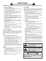
Look for this symbol to point out im-
portant safety precautions. It means
CAUTION!!! BECOME ALERT!!! YOUR
SAFETY IS INVOLVED.
SAFETY RULES
WARNING
The engine exhaust from this product con-
tains chemicals known to the State of Califor-
nia to cause cancer, birth defects, or other
reproductive harm.
CAUTION: Always disconnect spark plug
wire and place wire where it cannot contact
spark plug in order to prevent accidental
starting when setting up, transporting,
adjusting or making repairs.

3
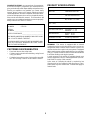
PRODUCT SPECIFICATIONS
HORSEPOWER: 22.0
GASOLINE CAPACITY 3.5 GALLONS
AND TYPE: UNLEADED REGULAR
OIL TYPE (API-SF/SG): SAE 10W30 (above 32°F)
SAE 5W-30 (below 32°F)
OIL CAPACITY: W/ FILTER: 4.2 PINTS
W/O FILTER: 3.7 PINTS
SPARK PLUG: CHAMPION RC12YC
(GAP: .040")
VALVE CLEARANCE NOT ADJUSTABLE
GROUND SPEED (MPH): FORWARD: 0 – 5.6
REVERSE: 0 – 2.5
TIRE PRESSURE: FRONT: 14 PSI
REAR: 10 PSI
CHARGING SYSTEM: 15 AMPS @ 3600 RPM
BLADE BOLT TORQUE: 30–35 FT. LBS.
CONGRATULATIONS on your purchase of a new tractor.
It has been designed, engineered and manufactured to
give you the best possible dependability and performance.
Should you experience any problem you cannot easily
remedy, please contact your nearest authorized service
center/department. We have competent, well-trained tech-
nicians and the proper tools to service or repair this tractor.
Please read and retain this manual. The instructions will
enable you to assemble and maintain your tractor properly.
Always observe the “SAFETY RULES”.
CUSTOMER RESPONSIBILITIES
• Read and observe the safety rules.
• Follow a regular schedule in maintaining, caring for and
using your tractor.
• Follow the instructions under “Customer Responsibili-
ties” and “Storage” sections of this owner’s manual.
MODEL
NUMBER GTH220
SERIAL
NUMBER ____________________________________
DATE OF PURCHASE __________________________
THE MODEL AND SERIAL NUMBERS WILL BE FOUND
ON A PLATE UNDER THE SEAT.
YOU SHOULD RECORD BOTH SERIAL NUMBER AND
DATE OF PURCHASE AND KEEP IN A SAFE PLACE
FOR FUTURE REFERENCE.
WARNING: This tractor is equipped with an internal
combustion engine and should not be used on or near any
unimproved forest-covered, brush-covered or grass-cov-
ered land unless the engine’s exhaust system is equipped
with a spark arrester meeting applicable local or state laws
(if any). If a spark arrester is used, it should be maintained
in effective working order by the operator.
A spark arrester for the muffler is available through your
nearest authorized service center/department (See RE-
PAIR PARTS section of this manual).
In the state of California the above is required by law
(Section 4442 of the California Public Resources Code).
Other states may have similar laws. Federal laws apply on
federal lands.

4
TABLE OF CONTENTS
SAFETY RULES ........................................................... 2
PRODUCT SPECIFICATIONS...................................... 3
CUSTOMER RESPONSIBILITIES..................... 3, 16-19
WARRANTY ................................................................ 55
ASSEMBLY ............................................................... 6-9
OPERATION .......................................................... 10-15
MAINTENANCE SCHEDULE ..................................... 16
SERVICE AND ADJUSTMENTS ........................... 20-28
STORAGE.................................................................... 27
TROUBLESHOOTING ........................................... 30-31
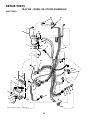
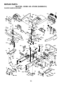
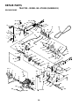
REPAIR PARTS..................................................... 34-52
INDEX
E
Electrical:
Interlocks and Relays .................. 25
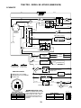
Schematic.................................... 33
Wiring Diagram............................ 35
Engine:
Air Filter ....................................... 19
Air Screen.................................... 18
Cooling Fins ................................ 19
Oil Change .................................. 18
Oil Level ...................................... 18
Oil Type ................................... 14,18
Preparation.................................. 14
Starting......................................... 14
Storage......................................... 29
F
Filter:
Air Filter ....................................... 19
Fuel .............................................. 19
Oil................................................. 19
Fuel:
Storage......................................... 29
Type ............................................. 14
Fuse .................................................... 26
H
Headlights ........................................... 26
Hood Removal/Installation .................. 26
L
Leveling Mower Deck ......................... 20
Lubrication:
Chart ............................................ 16
Engine .......................................... 18
M
Maintenance Schedule ....................... 16
Mower:
Adjustment, Front-to-Back ........... 21
Adjustment, Side-to-Side ............. 20
Blade Replacement ..................... 17
Blade Sharpening ........................ 17
Cutting Height.............................. 12
Installation ................................... 20
Operation..................................... 13
Removal ...................................... 20
Mowing Tips ....................................... 15
Muffler ................................................. 19
Spark Arrester .......................... 3,42
O
Oil:
Cold Weather Conditions........ 15,18
Engine ..................................... 14,18
Storage......................................... 29
Operation....................................... 10-15
Operating Mower ................................ 13
Options:
Spark Arrester .......................... 3,42
P
Parking Brake ...................................... 12
Parts Bag............................................... 5
Parts, Replacement/Repair............ 34-52
Product Specifications. ......................... 3
R
Repair Parts................................... 34-52
S
Safety Rules .......................................... 2
Seat....................................................... 7
Service and Adjustments ............... 20-28
Carburetor .................................... 28
Clutch Pulley ............................... 23
Fuse ............................................. 26
Hood Removal/Installation........... 26
Motion Drive Belt
Removal/Replacement ........... 24
Mower Drive Belt
Removal/Replacement ........... 21
Mower Blade Drive Belt
Removal/Replacement ........... 22
Mower Adjustment
Front-to-Back.......................... 21
Side-to-Side............................ 20
Mower Removal/Installation......... 20
Tire Care .............................. 7,17,25
Slope Guide Sheet ............................. 54
Spark Plug(s)....................................... 19
Specifications ....................................... 3
Starting the Engine ............................. 15
Steering Wheel ................................ 6,24
Stopping the Tractor ........................... 12
Storage................................................ 29
T
Throttle Control Cable Adjustment ...... 27
Tires. ........................................... 7,17,25
Troubleshooting Chart ................... 30-31
Transaxle............................................. 18
W
Warranty.............................................. 55
Wiring Diagram.................................... 34
Wiring Schematic................................ 33
A
Adjustments:
Brake............................................ 22
Carburetor ................................... 28
Clutch Pulley................................ 22
Gauge Wheels............................. 13
Mower
Front-To-Back......................... 21
Side-To-Side........................... 20
Throttle Control Cable.................. 27
Air Filter, Engine ................................. 19
Air Screen, Engine.............................. 19
Assembly........................................... 6-9
B
Battery:
Charging......................................... 7
Cleaning ...................................... 19
Levels........................................ 9,17
Starting with Weak Battery .......... 25
Storage......................................... 29
Terminals..................................... 17
Belt:
Motion Drive
Removal/Replacement ........... 24
Mower Drive
Removal/Replacement ........... 21
Mower Blade Drive
Removal/Replacement ........... 22
Blade:
Sharpening .................................. 17
Replacement ............................... 17
Brake Adjustment ............................... 23
C
Carburetor Adjustment........................ 27
Clutch Pulley....................................... 23
Controls, Tractor................................. 11
Customer Responsibilities ............. 16-19
Engine:
Air Filter ................................... 19
Air Screen................................ 18
Cooling Fins............................. 19
Engine Oil................................ 18
Fuel Filter ................................ 19
Spark Plug(s)........................... 19
Tractor:
Battery ..................................... 17
Blade ....................................... 17
Lubrication Chart ..................... 16
Maintenance Schedule ............ 16
Tire Care ......................... 7,17,25
Transaxle................................. 18
Cutting Height, Mower ........................ 12

5
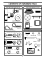
CONTENTS OF HARDWARE PACK
(2) Hex Bolts 1/4-20 x 3/4
(2) Washers 9/32 x 5/8 x 16 Ga.(2) Lock Washers 1/4
(2) Hex Nuts 1/4-20
Parts packed separately in carton
Parts Bag contents shown full size
Parts bag contents not shown full size
(1) Shoulder Bolt
5/16-18
(1) Washer
17/32 x 1-3/16 x 12 Gauge
(1) Knob
(3) Retainer Springs
(double loop)
(4) Retainer Springs (single loop)
Seat
Parts Bag
Manual
Steering Wheel
Nose Roller
(2) Front Link Assemblies
Steering
Wheel
Insert
Nose
Roller
Brackets
(2) Keys
Slope Sheet
(2) Hex Bolts 3/8-16 x 1
(2) Washers 17/32 x 7/8 x 16 Ga.
(2) Nylon Locknuts 3/8-16
(4) Washers 13/32 x 13/16 x 16 Ga.
(4) Crownlock Nuts 3/8-16
(4) Carriage Bolts
3/8-16 x 1-1/4
Front Bumper
(2) Shoulder
Bolts
(2) Gauge
Wheels
(2) Washers 3/8
x 7/8 x 14 Gauge
(2) Center-
lock Nuts

ASSEMBLY
6
Your new tractor has been assembled at the factory with exception of those parts left unassembled for shipping purposes.
To ensure safe and proper operation of your tractor all parts and hardware you assemble must be tightened securely. Use
the correct tools as necessary to insure proper tightness.
TOOLS REQUIRED FOR ASSEMBLY
A socket wrench set will make assembly easier. Standard
wrench sizes are listed.
(2) 7/16" wrenches (1) Tire pressure gauge
(2) 9/16" wrenches (1) Utility knife
(1) 1/2" wrench (1) 3/4" socket w/drive ratchet
When right or left hand is mentioned in this manual, it
means when you are in the operating position (seated
behind the steering wheel).
TO REMOVE TRACTOR FROM CARTON
UNPACK CARTON
• Remove all accessible loose parts and parts cartons
from carton (See page 5).
• Cut, from top to bottom, along lines on all four corners
of carton, and lay panels flat.
• Remove mower and packing materials.
• Check for any additional loose parts or cartons and
remove.
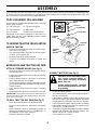
BEFORE ROLLING TRACTOR OFF SKID
ATTACH STEERING WHEEL (See Fig. 1)
• Remove hex bolt, lock washer and large flat washer
from steering shaft.
• Position front wheels of the tractor so they are pointing
straight forward.
• Position steering wheel so cross bars are horizontal
(left to right) and slide onto adapter.
• Secure steering wheel to steering shaft with hex bolt,
lock washer and large flat washer previously removed.
Tighten securely.
• Snap steering wheel insert into center of steering
wheel.
• Remove protective plastic from tractor hood and grill.
IMPORTANT: CHECK FOR AND REMOVE ANY STAPLES
IN SKID THAT MAY PUNCTURE TIRES WHERE TRACTOR
IS TO ROLL OFF SKID.
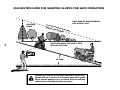
TO ROLL TRACTOR OFF SKID (See Fig. 7)
• Raise attachment lift lever to its highest position.
• Release parking brake by depressing clutch/brake
pedal.
• Place freewheel control in freewheeling position to
disengage transmission (See “TO TRANSPORT” in
the Operation section of this manual).
• Roll tractor backwards off skid.
FIG. 1
STEERING WHEEL
INSERT
STEERING
WHEEL
ADAPTER
STEERING
SHAFT
STEERING
WHEEL
HEX BOLT
LOCKWASHER
FLAT WASHER
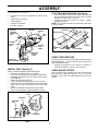
CONNECT BATTERY (See Fig. 2)
CAUTION: Do not short battery termi-
nals. Before connecting battery, re-
move metal bracelets, wristwatch
bands, rings, etc.
Positive terminal must be connected
first to prevent sparking from acciden-
tal grounding.
• Lift hood to raised position.
• Open terminal access doors, remove terminal protec-
tive caps and discard.
• If this battery is put into service after month and year
indicated on label (label located between terminals)
charge battery for minimum of one hour at 6-10 amps.
• First connect RED battery cable to positive (+) battery
terminal with hex bolt, flat washer, lock washer and hex
nut as shown. Tighten securely.
• Connect BLACK grounding cable to negative (-) battery
terminal with remaining hex bolt, flat washer, lock
washer and hex nut. Tighten securely.
• Close terminal access doors.

ASSEMBLY
7
Use terminal access doors for:
• Inspection for secure connections (to tighten hard-
ware).
• Inspection for corrosion.
• Testing battery.
• Jumping (if required).
• Periodic charging.
VENT HOLE
(KEEP CLEAN)
TERMINAL
ACCESS
DOOR
FIG. 2
FLAT
WASHER
HEX
BOLT
LOCK
WASHER
HEX NUT
DISCARD
TERMINAL
PROTECTIVE
CAPS
POSITIVE
(RED)
CABLE
NEGATIVE
(BLACK)
CABLE
SEAT
SEAT PAN
SHOULDER
BOLT
TO ATTACH NOSE ROLLER (See Fig. 4)
• Position brackets, washers and nose roller between
deck mounting brackets as shown. Be sure to position
brackets on correct side, as shown.
• Install hex bolts and locknuts as shown. Tighten
hardware securely.
NOTE: Be sure tabs brackets are positioned in tab holes
in deck brackets.
FIG. 4
"B" BRACKET TAB
WASHER
LOCKNUT
TAB HOLE
NOSE ROLLER
"A"
BRACKET
TAB
HEX
BOLT
CHECK TIRE PRESSURE
The tires on your tractor were overinflated at the factory for
shipping purposes. Correct tire pressure is important for
best cutting performance.
• Reduce tire pressure to PSI shown in “PRODUCT
SPECIFICATIONS” on page 3 of this manual.
CHECK BRAKE SYSTEM
After you learn how to operate your tractor, check to see
that the brake is properly adjusted. See “TO ADJUST
BRAKE” in the Service and Adjustments section of this
manual.
INSTALL SEAT (See Fig. 3)
Adjust seat before tightening adjustment knob.
• Remove cardboard packing on seat pan.
• Place seat on seat pan and assemble shoulder bolt.
• Assemble adjustment knob and flat washer loosely.
Do not tighten.
• Tighten shoulder bolt securely.
• Lower seat into operating position and sit on seat.
• Slide seat until a comfortable position is reached which
allows you to press clutch/brake pedal all the way
down.
• Get off seat without moving its adjusted position.
• Raise seat and tighten adjustment knob securely.
FIG. 3
ADJUSTMENT KNOB
FLAT
WASHER

ASSEMBLY
8
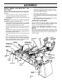
INSTALL MOWER AND DRIVE BELT (See
Figs. 5 and 7)
Be sure tractor is on level surface and mower suspension
arms are raised with attachment lift control. Engage park-
ing brake.
• Cut and remove tie down securing anti-sway bar.
Swing anti-sway bar to left side of mower deck.
• Slide mower under tractor with discharge guard to right
side of tractor.
IMPORTANT: CHECK BELT FOR PROPER ROUTING IN
ALL MOWER PULLEY GROOVES. INSTALL BELT INTO
ELECTRIC CLUTCH PULLEY GROOVE.
• Install one front link in top hole of the L.H. front mower
bracket and L.H. front suspension bracket. Retain with
two single loop retainer springs as shown.
• Install second front link in R.H. front suspension bracket
only and retain with single loop retainer spring as
shown.
• Slide right side of mower deck back and install link in
top hole of R.H. front mower bracket. Retain with single
loop retainer spring as shown.
• Turn height adjustment knob counterclockwise until it
stops.
• Lower mower linkage with attachment lift control.
• Place the suspension arms on inward pointing deck
pins. If necessary, rock and raise front of mower to
align deck pins with the holes in suspension arms.
Retain with double loop retainer springs.
• Connect anti-sway bar to chassis bracket under left
footrest and retain with double loop retainer spring.
• Turn height adjustment knob clockwise to remove
slack from mower suspension.
• Raise deck to highest position.
• Assemble gauge wheels as shown using long shoulder
bolts, 3/8 washers, and 3/8-16 center locknuts. Tighten
securely.
• Adjust gauge wheels before operating mower as shown
in the Operation section of this manual.
CHECK DECK LEVELNESS
For best cutting results, mower housing should be properly
leveled. See “TO LEVEL MOWER HOUSING” in the
Service and Adjustments section of this manual.
CHECK FOR PROPER POSITION OF ALL
BELTS
See the figures that are shown for replacing motion, mower
drive, and mower blade drive belts in the Service and
Adjustments section of this manual. Verify that the belts are
routed correctly.
SINGLE
LOOP RETAINER
SPRINGS
SHOULDER
BOLT
ANTI-SWAY
BAR
GAUGE
WHEEL
3/8 WASHER
IDLER
PULLEY
FRONT MOWER
BRACKET
SUSPENSION
ARMS
L.H. GAUGE
WHEEL BAR
DOUBLE LOOP
RETAINER SPRING
DISCHARGE
GUARD
FRONT
SUSPENSION
BRACKETS
FRONT
LINKS
CHASSIS
BRACKET
3/8-16
CENTER
LOCKNUT
ELECTRIC
CLUTCH
PULLEY
FIG. 5
DOUBLE LOOP
RETAINER SPRING
(Inward pointing
deck pins)

ASSEMBLY
9
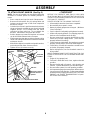
TO ATTACH FRONT BUMPER (See Fig. 6)
NOTE: For ease of assembly, you may wish to obtain the
assistance of another person for mounting bumper to
tractor.
• Press or tap the end caps into ends of bumper tube.
• Remove and discard the four (4) carriage bolts and
locknuts securing the top of both front suspension
brackets to chassis.
• On both sides of chassis, position extension bracket as
shown and loosely assemble to rear chassis hole with
supplied 3/8-16 x 1-1/4 carriage bolt and 3/8-16
crownlock nut from parts bag. Do not tighten the
brackets. Allow them to hang from the chassis.
• Position bumper and extension brackets so brackets
can be slid inside flattened ends of bumper.
• Slide bumper onto brackets and pivot upwards to align
center hole in bumper with holes in extension brackets
and tractor chassis.
• With all holes aligned, assemble carriage bolt, washer,
and locknut to both sides of tractor chassis.
• Tighten all four (4) locknuts securely.
FRONT
SUSPENSION
BRACKET
SUPPLIED
CARRIAGE BOLT
BUMPER
END CAP
Slide Onto Extension
Brackets And Pivot
Upwards
SUPPLIED
CARRIAGE
BOLT
EXTENSION
BRACKET
WASHER SUPPLIED LOCKNUT
SUPPLIED
LOCKNUT
FIG. 6
✓
CHECKLIST
BEFORE YOU OPERATE AND ENJOY YOUR NEW
TRACTOR, WE WISH TO ASSURE THAT YOU RECEIVE
THE BEST PERFORMANCE AND SATISFACTION FROM
THIS QUALITY PRODUCT.
PLEASE REVIEW THE FOLLOWING CHECKLIST:
✓ All assembly instructions have been completed.
✓ No remaining loose parts in carton.
✓ Battery is properly prepared and charged. (Minimum
1 hour at 6 amps).
✓ Seat is adjusted comfortably and tightened securely.
✓ All tires are properly inflated. (For shipping purposes,
the tires were overinflated at the factory).
✓ Be sure mower deck is properly leveled side-to-side/
front-to-rear for best cutting results. (Tires must be
properly inflated for leveling).
✓ Check mower and drive belts. Be sure they are routed
properly around pulleys and inside all belt keepers.
✓ Check wiring. See that all connections are still secure
and wires are properly clamped.
✓ Before driving tractor, be sure freewheel control is in
drive position.
WHILE LEARNING HOW TO USE YOUR TRACTOR, PAY
EXTRA ATTENTION TO THE FOLLOWING IMPORTANT
ITEMS:
✓ Engine oil is at proper level.
✓ Fuel tank is filled with fresh, clean, regular unleaded
gasoline.
✓ Become familiar with all controls - their location and
function. Operate them before you start the engine.
✓ Be sure brake system is in safe operating condition.
✓ It is important to purge the transmission before operat-
ing your tractor for the first time. Follow proper starting
and transmission purging instructions (See “TO START
ENGINE” and “PURGE TRANSMISSION” in Opera-
tion section of this manual).

OPERATION
10
These symbols may appear on your tractor or in literature supplied with the product. Learn and understand their meaning.
BATTERY CAUTION OR
WARNING
REVERSE FORWARD FAST SLOW
ENGINE ON ENGINE OFF OIL PRESSURE CLUTCH LIGHTS ON LIGHTS OFF
FUEL CHOKE MOWER HEIGHT DIFFERENTIAL
LOCK
PARKING BRAKE
LOCKED
UNLOCKED
REVERSE NEUTRAL HIGH LOW
ATTACHMENT
CLUTCH ENGAGED
MOWER LIFT
DANGER, KEEP HANDS AND FEET AWAY
HYDROSTATIC FREE WHEEL
(Hydro Models only)
PARKING BRAKE
IGNITIONATTACHMENT
CLUTCH DISENGAGED
P

11
OPERATION
KNOW YOUR TRACTOR
READ THIS OWNER'S MANUAL AND SAFETY RULES BEFORE OPERATING YOUR TRACTOR.
Compare the illustrations with your tractor to familiarize yourself with the location of various controls and adjustments. Save
this manual for future reference.
FIG. 7
THROTTLE
CONTROL
CHOKE
CONTROL
ATTACHMENT CLUTCH SWITCH - Used to engage mower
blades or other attachments mounted to your tractor.
LIFT LEVER - Used to raise and lower mower deck or other
attachments mounted to your tractor.
LIFT LEVER PLUNGER - Used to release attachment lift
lever when changing its position.
CLUTCH/BRAKE PEDAL - Used for declutching and
braking the tractor and starting the engine.
MOTION CONTROL - Selects the speed and direction of
tractor.
CHOKE CONTROL - Used when starting a cold engine.
LIGHT SWITCH - Turns the headlights on and off.
THROTTLE CONTROL - Used to control engine speed.
FREEWHEEL CONTROL - Disengages transmission for
pushing or slowly towing the tractor with the engine off.
IGNITION SWITCH - Used to start and stop the engine.
HOURMETER - Indicates hours of operation.
PARKING BRAKE LEVER - Locks clutch/brake pedal into
the brake position.
HEIGHT ADJUSTMENT KNOB - Used to adjust the mower
height.
INDICATOR LIGHTS - Indicates low fuel level, attachment
engagement, low battery voltage, and low oil pressure.
Our tractors conform to the safety standards of the American National Standards Institute.
MOTION
CONTROL
LEVER
PARKING BRAKE
LEVER
HEIGHT
ADJUSTMENT
KNOB
IGNITION SWITCH
CLUTCH/BRAKE
PEDAL
LIFT LEVER
LIGHT SWITCH
ATTACHMENT
CLUTCH SWITCH
FREE WHEEL CONTROL
HOURMETER
INDICATOR LIGHTS
LIFT LEVER
PLUNGER

OPERATION
12
HOW TO USE YOUR TRACTOR
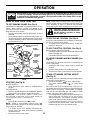
TO SET PARKING BRAKE (See Fig. 8)
Your tractor is equipped with an operator presence sensing
switch. When engine is running, any attempt by the
operator to leave the seat without first setting the parking
brake will shut off the engine.
• Depress clutch/brake pedal into full “BRAKE” position
and hold.
• Place parking brake lever in “ENGAGED” position and
release pressure from clutch/brake pedal. Pedal should
remain in “BRAKE” position. Make sure parking brake
will hold tractor secure.
The operation of any tractor can result in foreign objects thrown into the eyes, which can result
in severe eye damage. Always wear safety glasses or eye shields while operating your tractor
or performing any adjustments or repairs. We recommend a wide vision safety mask over the
spectacles or standard safety glasses.
NOTE: Under certain conditions when unit is standing idle
with the engine running, hot engine exhaust gases may
cause “browning” of grass. To eliminate this possibility,
always stop engine when stopping tractor on grass areas.
CAUTION: Always stop tractor com-
pletely, as described above, before leav-
ing the operator’s position; to empty
grass catcher, etc.
TO USE CHOKE CONTROL (See Fig. 8)
Use choke control whenever you are starting a cold engine.
Do not use to start a warm engine.
• To engage choke control, pull knob out. Slowly push
knob in to disengage.
TO USE THROTTLE CONTROL (See Fig. 8)
Always operate engine at full throttle.
• Operating engine at less than full throttle reduces the
battery charging rate.
• Full throttle offers the best mower performance.
TO MOVE FORWARD AND BACKWARD (See
Fig. 8)
The direction and speed of movement is controlled by the
motion control lever.
• Start tractor with motion control lever in neutral (N)
position.
• Release parking brake and clutch/brake pedal.
• Slowly move motion control lever to desired position.
TO ADJUST MOWER CUTTING HEIGHT
(See Fig. 8)
The cutting height is controlled by turning the height adjust-
ment knob in desired direction.
• Turn knob clockwise (
) to raise cutting height.
• Turn knob counterclockwise (
) to lower cutting
height.
The cutting height range is approximately 1-1/4" to 4-1/4".
The heights are measured from the ground to the blade tip
with the engine not running. These heights are approxi-
mate and may vary depending upon soil conditions, height
of grass and types of grass being mowed.
• The average lawn should be cut to approximately 2-1/2
inches during the cool season and to over 3 inches
during hot months. For healthier and better looking
lawns, mow often and after moderate growth.
• For best cutting performance, grass over 6 inches in
height should be mowed twice. Make the first cut
relatively high; the second to desired height.
FIG. 8
“DRIVE”
POSITION
PARKING
BRAKE
“ENGAGED”
POSITION
IGNITION
KEY
HEIGHT
ADJUSTMENT
KNOB
“DISENGAGED”
POSITION
STOPPING (See Fig. 8)
MOWER BLADES -
• Move attachment clutch switch to “DISENGAGED”
position.
GROUND DRIVE -
• Depress clutch/brake pedal into full “BRAKE” position.
• Move motion control lever to neutral (N) position.
IMPORTANT: THE MOTION CONTROL LEVER DOES
NOT RETURN TO NEUTRAL (N) POSITION WHEN THE
CLUTCH/BRAKE PEDAL IS DEPRESSED.
ENGINE -
• Move throttle control to slow (
) position.
NOTE: Failure to move throttle control to slow (
)
position and allowing engine to idle before stopping may
cause engine to “backfire”.
• Turn ignition key to “OFF” position and remove key.
Always remove key when leaving tractor to prevent
unauthorized use.
• Never use choke to stop engine.
ATTACHMENT CLUTCH
SWITCH PULL OUT TO
“ENGAGE”
PUSH IN TO
“DISENGAGE”
MOTION
CONTROL
LEVER
CLUTCH/BRAKE
PEDAL “BRAKE”
POSITION
CHOKE
CONTROL
THROTTLE
CONTROL
LEVER

13
OPERATION
TO OPERATE ON HILLS
CAUTION: Do not drive up or down
hills with slopes greater than 15
° and
do not drive across any slope.
• Choose the slowest speed before starting up or down
hills.
• Avoid stopping or changing speed on hills.
• If slowing is necessary, move throttle control lever to
slower position.
• If stopping is absolutely necessary, push clutch/brake
pedal quickly to brake position and engage parking
brake.
• Move motion control lever to neutral (N) position.
IMPORTANT: THE MOTION CONTROL LEVER DOES
NOT RETURN TO NEUTRAL (N) POSITION WHEN THE
CLUTCH/BRAKE PEDAL IS DEPRESSED.
• To restart movement, slowly release parking brake and
clutch/brake pedal.
• Slowly move motion control lever to slowest setting.
• Make all turns slowly.
TO TRANSPORT (See Figs. 7 and 11)
When pushing or towing your tractor, be sure to disengage
transmission by placing freewheel control in freewheeling
position. Free wheel control is located at the rear drawbar
of tractor.
• Raise attachment lift to highest position with attach-
ment lift control.
• Remove retainer spring from freewheel control rod.
• Push control rod in to disengage transmission and
reinsert retainer spring into control rod hole now on
back side of the bracket.
• Do not push or tow tractor at more than two (2) MPH.
• To reengage transmission, reverse above procedure.
NOTE: To protect hood from damage when transporting
your tractor on a truck or a trailer, be sure hood is closed and
secured to tractor. Use an appropriate means of tying hood
to tractor (rope, cord, etc.).
FIG. 11
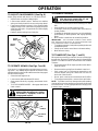
TO OPERATE MOWER (See Figs. 7 and 8)
Your tractor is equipped with an operator presence sens-
ing switch. Any attempt by the operator to leave the seat
with the engine running and the attachment clutch engaged
will shut off the engine.
• Select desired height of cut.
• Lower mower with attachment lift control.
• Start mower blades by engaging attachment clutch
control.
• TO STOP MOWER BLADES - disengage attachment
clutch control.
CAUTION: Do not operate the mower
without either the entire grass catcher,
on mowers so equipped, or the dis-
charge guard in place.
R.H.
RUNNER
DISCHARGE
GUARD
FIG. 10
TO ADJUST GAUGE WHEELS (See Fig. X)
Adjust gauge wheels with tractor on a flat level surface.
• Adjust mower to desired cutting height.
• Lower mower with lift control. Remove rear retainer
spring and clevis pin which secure each gauge wheel.
• Lower gauge wheels to ground. Raise gauge wheels
slightly to align holes in bracket and gauge wheel bar
and insert clevis pins. Gauge wheels should be slightly
off the ground.
• Replace retainer springs into clevis pins.
GAUGE
WHEEL
GAUGE
WHEEL BAR
CLEVIS
PIN
RETAINER
SPRING
BRACKET
FIG. 9

OPERATION
14
DEPRESS
FOOT
PEDAL
DISENGAGE
ATTACHMENT
INDICATOR LIGHTS
Located on the dash of your tractor, these lights alert you
to necessary steps required to start your tractor or, while
tractor is running, alerts you to a serious problem which
requires immediate attention.
• Indicates you must depress clutch/brake
pedal fully to start tractor.
• Indicates you must disengage attachment
clutch control to start tractor.
• Indicates low oil pressure in your engine.
Light should come on when engine is not
running and key switch is in "ON" position.
This is a test to be sure light is working
and a reminder to always check oil level
before starting engine.
CHECK
OIL
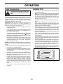
TO START ENGINE (See Fig. 8)
When starting engine for the first time or if engine has run
out of fuel, it will take extra cranking time to move fuel from
the tank to the engine.
• Depress clutch/brake pedal and set parking brake.
• Place motion control lever in neutral (N) position.
• Move attachment clutch to “DISENGAGED” position.
• Pull choke control out to choke (
) position for cold
engine start. For warm engine start do not use choke
control.
• Move throttle control to midway between fast (
) and
slow (
) positions.
• Insert key into ignition and turn key clockwise to “START”
position and release key as soon as engine starts. Do
not run starter continuously for more than fifteen
seconds per minute. If engine does not start after
several attempts, move throttle control to fast (
)
position, wait a few minutes and try again.
• When engine starts, slowly push choke control in.
• Move throttle control to fast (
) position.
• Allow engine to warm up for a few minutes before
engaging drive or attachments.
IMPORTANT: COLD STARTING FOR HYDRO (BELOW
40°F) - AFTER STARTING ENGINE AND BEFORE
DRIVING, LET TRANSMISSION WARM UP FOR ONE (1)
MINUTE BY PLACING MOTION CONTROL LEVER IN
NEUTRAL (N) POSITION AND RELEASING CLUTCH/
BRAKE PEDAL.
NOTE: If at a high altitude (above 3000 feet) or in cold
temperatures (below 32°F), the carburetor fuel mixture
may need to be adjusted for best engine performance. See
“TO ADJUST CARBURETOR” in the Service and Adjust-
ments section of this manual.
OIL FILL
CAP/DIPSTICK
FIG. 12
ADD GASOLINE
• Fill fuel tank. Use fresh, clean, regular unleaded
gasoline. (Use of leaded gasoline will increase carbon
and lead oxide deposits and reduce valve life).
IMPORTANT: WHEN OPERATING IN TEMPERATURES
BELOW 32°F(0°C), USE FRESH, CLEAN WINTER GRADE
GASOLINE TO HELP INSURE GOOD COLD WEATHER
STARTING.
WARNING: Experience indicates that alcohol blended
fuels (called gasohol or using ethanol or methanol) can
attract moisture which leads to separation and formation of
acids during storage. Acidic gas can damage the fuel
system of an engine while in storage. To avoid engine
problems, the fuel system should be emptied before stor-
age of 30 days or longer. Drain the gas tank, start the
engine and let it run until the fuel lines and carburetor are
empty. Use fresh fuel next season. See Storage Instruc-
tions for additional information. Never use engine or
carburetor cleaner products in the fuel tank or permanent
damage may occur.
CAUTION: Fill to bottom of gas tank
filler neck. Do not overfill. Wipe off any
spilled oil or fuel. Do not store, spill or
use gasoline near an open flame.
BEFORE STARTING THE ENGINE
CHECK ENGINE OIL LEVEL (See Fig. 12)
• The engine in your tractor has been shipped, from the
factory, already filled with summer weight oil.
• Check engine oil with tractor on level ground.
• Unthread and remove oil fill cap/dipstick; wipe oil off.
Reinsert the dipstick into the tube and rest oil fill cap on
the tube. Do not thread the cap onto the tube. Remove
and read oil level. If necessary, add oil until “FULL”
mark on dipstick is reached. Do not overfill.
• For cold weather operation you should change oil for
easier starting (See “OIL VISCOSITY CHART” in the
Customer Responsibilities section of this manual).
• To change engine oil, see the Customer Responsibili-
ties section in this manual.

15
OPERATION
PURGE TRANSMISSION
CAUTION: Never engage or disengage
freewheel lever while the engine is run-
ning.
To ensure proper operation and performance, it is recom-
mended that the transmission be purged before operating
tractor for the first time. This procedure will remove any
trapped air inside the transmission which may have devel-
oped during shipping of your tractor.
IMPORTANT: SHOULD YOUR TRANSMISSION REQUIRE
REMOVAL FOR SERVICE OR REPLACEMENT, IT
SHOULD BE PURGED AFTER REINSTALLATION
BEFORE OPERATING THE TRACTOR.
• Place tractor safely on level surface with engine off and
parking brake set.
• Disengage transmission by placing freewheel control
in freewheeling position (See “TO TRANSPORT” in
this section of this manual).
• Sitting in the tractor seat, start engine. After the engine
is running, move throttle control to slow (
) position.
With motion control lever in neutral (N) position, slowly
disengage clutch/brake pedal.
• Move motion control lever to full forward position and
hold for five (5) seconds. Move lever to full reverse
position and hold for five (5) seconds. Repeat this
procedure three (3) times.
NOTE: During this procedure there will be no movement of
drive wheels. The air is being removed from hydraulic drive
system.
• Move motion control lever to neutral (N) position. Shut
off engine and set parking brake.
• Engage transmission by placing freewheel control in
driving position (See “TO TRANSPORT” in this section
of this manual).
• Sitting in the tractor seat, start engine. After the engine
is running, move throttle control to half (1/2) speed.
With motion control lever in neutral (N) position, slowly
disengage clutch/brake pedal.
• Slowly move motion control lever forward. After the
tractor moves approximately five (5) feet, slowly move
motion control lever to reverse position. After the
tractor moves approximately five (5) feet, return the
motion control lever to the neutral (N) position. Repeat
this procedure with the motion control lever three (3)
times.
• Your tractor is now purged and ready for normal
operation.
MOWING TIPS
• Tire chains cannot be used when the mower housing
is attached to tractor.
• Mower should be properly leveled for best mowing
performance. See “TO LEVEL MOWER HOUSING” in
the Service and Adjustments section of this manual.
• Use the runner on the right hand side of mower as a
guide. The blade cuts approximately an inch outside
the runner (See Fig. 10).
• The left hand side of mower should be used for trim-
ming.
• Drive so that clippings are discharged onto the area
that has been cut. Have the cut area to the right of the
tractor. This will result in a more even distribution of
clippings and more uniform cutting.
• When mowing large areas, start by turning to the right
so that clippings will discharge away from shrubs,
fences, driveways, etc. After one or two rounds, mow
in the opposite direction making left hand turns until
finished (See Fig. 13).
• If grass is extremely tall, it should be mowed twice to
reduce load and possible fire hazard from dried clip-
pings. Make first cut relatively high; the second to the
desired height.
• Do not mow grass when it is wet. Wet grass will plug
mower and leave undesirable clumps. Allow grass to
dry before mowing.
• Always operate engine at full throttle when mowing to
assure better mowing performance and proper dis-
charge of material. Regulate ground speed by select-
ing a low enough gear to give the mower cutting
performance as well as the quality of cut desired.
• When operating attachments, select a ground speed
that will suit the terrain and give best performance of
the attachment being used.
FIG. 13

16
CUSTOMER RESPONSIBILITIES
BEFORE EACH USE
✔
✔✔
✔
✔
T
R
A
C
T
0
R
Adjust Motion Drive Belt(s) Tension
Inspect Muffler/Spark Arrester
Lubrication Chart
Check Brake Operation
Clean Air Filter
Change Engine Oil
Replace Air Filter Paper Cartridge
Replace Spark Plug
Check Battery Level/Recharge
Check Tire Pressure
Clean Battery and Terminals
FILL IN DATES
AS YOU COMPLETE
REGULAR SERVICE
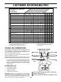
MAINTENANCE SCHEDULE
EVERY 8 HOURS
EVERY 25 HOURS
EVERY 50 HOURS
EVERY 100 HOURS
EVERY SEASON
SERVICE DATES
Check for Loose Fasteners
FIRST 2 HOURS
BEFORE STORAGE
Check Engine Oil Level
Clean Engine Cooling Fins
Sharpen/Replace Mower Blades
Clean Air Screen
1 - Change more often when operating under a heavy load or in high ambient temperatures.
2 - Service more often when operating in dirty or dusty conditions.
3 - If equipped with oil filter, change oil every 50 hours.
4 - Replace blades more often when mowing in sandy soil.
E
N
G
I
N
E
Replace Oil Filter (If equipped)
Check Transaxle Cooling
Adjust Blade Belt(s) Tension
Replace Fuel Filter
✔
✔
✔
✔
✔
✔
✔
✔
✔
✔
✔
✔
✔
✔
✔
✔
✔
✔
✔
✔
✔
✔
✔
✔
1
4
2
2
2
2
5 - If equipped with adjustable system.
6 - Not required if equipped with maintenance-free battery.
7 - Tighten front axle pivot bolt to 35 ft.-lbs. maximum.
Do not overtighten.
1,
12,3,
2
5
5
6
✔
7
GENERAL RECOMMENDATIONS
The warranty on this tractor does not cover items that have
been subjected to operator abuse or negligence. To
receive full value from the warranty, operator must maintain
tractor as instructed in this manual.
Some adjustments will need to be made periodically to
properly maintain your tractor.
All adjustments in the Service and Adjustments section of
this manual should be checked at least once each season.
• Once a year you should replace the spark plug, clean
or replace air filter, and check blades and belts for
wear. A new spark plug and clean air filter assure
proper air-fuel mixture and help your engine run better
and last longer.
BEFORE EACH USE
• Check engine oil level.
• Check brake operation.
• Check tire pressure.
• Check for loose fasteners.
TIE ROD BALL JOINTS
1
FRONT WHEEL
BEARING ZERK
2
ENGINE
SPINDLE ZERK
FRONT WHEEL
BEARING ZERK
2
2
2
3
SPINDLE ZERK
STEERING
SECTOR GEAR
TEETH
2
LUBRICATION CHART
SPRAY SILICONE LUBRICANT (MOVE BOOTS TO LUBRICATE)
GENERAL PURPOSE GREASE
REFER TO CUSTOMER RESPONSIBILITIES “ENGINE” SECTION
IMPORTANT: DO NOT OIL OR GREASE THE PIVOT POINTS
WHICH HAVE SPECIAL NYLON BEARINGS. VISCOUS LUBRI-
CANTS WILL ATTRACT DUST AND DIRT THAT WILL SHORTEN
THE LIFE OF THE SELF-LUBRICATING BEARINGS. IF YOU
FEEL THEY MUST BE LUBRICATED, USE ONLY A DRY, POW-
DERED GRAPHITE TYPE LUBRICANT SPARINGLY.
2
1
3

17
CUSTOMER RESPONSIBILITIES
TRACTOR
Always observe safety rules when performing any mainte-
nance.
BRAKE OPERATION
If tractor requires more than six (6) feet stopping distance
at high speed in highest gear, then brake must be adjusted.
(See “TO ADJUST BRAKE” in the Service and Adjust-
ments section of this manual).
TIRES
• Maintain proper air pressure in all tires (See “PROD-
UCT SPECIFICATIONS” on page 3 of this manual).
• Keep tires free of gasoline, oil, or insect control chemi-
cals which can harm rubber.
• Avoid stumps, stones, deep ruts, sharp objects and
other hazards that may cause tire damage.
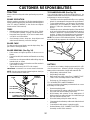
BLADE CARE
For best results mower blades must be kept sharp. Re-
place bent or damaged blades.
BLADE REMOVAL (See Fig. 14)
• Raise mower to highest position to allow access to
blades.
• Remove hex bolt, lock washer and flat washer securing
blade.
• Install new or resharpened blade with trailing edge up
towards deck as shown.
• Reassemble hex bolt, lock washer and flat washer in
exact order as shown.
• Tighten bolt securely (30-35 Ft. Lbs. torque).
IMPORTANT: BLADE BOLT IS GRADE 8 HEAT TREATED.
NOTE: We do not recommend sharpening blade - but if you
do, be sure the blade is balanced.
TO SHARPEN BLADE (See Fig. 15)
Care should be taken to keep the blade balanced. An
unbalanced blade will cause excessive vibration and even-
tual damage to mower and engine.
• The blade can be sharpened with a file or on a grinding
wheel. Do not attempt to sharpen while on the mower.
• To check blade balance, you will need a 5/8" diameter
steel bolt, pin, or a cone balancer. (When using a cone
balancer, follow the instructions supplied with bal-
ancer).
• Slide blade on to an unthreaded portion of the steel bolt
or pin and hold the bolt or pin parallel with the ground.
If blade is balanced, it should remain in a horizontal
position. If either end of the blade moves downward,
sharpen the heavy end until the blade is balanced.
NOTE: Do not use a nail for balancing blade. The lobes of
the center hole may appear to be centered, but are not.
5/8" BOLT
OR PIN
BLADE
CENTER HOLE
FIG. 15
MANDREL
ASSEMBLY
BLADE
TRAILING
EDGE UP
FLAT WASHER
LOCK WASHER
HEX BOLT (GRADE 8)*
*A GRADE 8 HEAT TREATED BOLT CAN BE
IDENTIFIED BY SIX LINES ON THE BOLT HEAD.
FIG. 14
BATTERY
Your tractor has a battery charging system which is suffi-
cient for normal use. However, periodic charging of the
battery with an automotive charger will extend its life.
• Keep battery and terminals clean.
• Keep battery bolts tight.
• Keep small vent holes open (See “CONNECT BAT-
TERY” in the Assembly section of this manual).
• Recharge at 6-10 amperes for 1 hour.
TO CLEAN BATTERY AND TERMINALS
Corrosion and dirt on the battery and terminals can cause
the battery to “leak” power.
• Remove terminal guard.
• Disconnect BLACK battery cable first then RED bat-
tery cable and remove battery from tractor.
• Wash battery with solution of four tablespoons of
baking soda to one gallon of water. Be careful not to get
the soda solution into the cells.
• Rinse the battery with plain water and dry.
• Clean terminals and battery cable ends with wire brush
until bright.
• Coat terminals with grease or petroleum jelly.
• Reinstall battery (See “CONNECT BATTERY” in the
Assembly section of this manual).

18
CUSTOMER RESPONSIBILITIES
TRANSAXLE COOLING
The fan and cooling fins of transmission should be kept
clean to assure proper cooling.
Do not attempt to clean fan or transmission while engine is
running or while the transmission is hot.
• Inspect cooling fan to be sure fan blades are intact and
clean.
• Inspect cooling fins for dirt, grass clippings and other
materials. To prevent damage to seals, do not use
compressed air or high pressure sprayer to clean
cooling fins.
TRANSAXLE PUMP FLUID
The transaxle was sealed at the factory and fluid mainte-
nance is not required for the life of the transaxle. Should the
transaxle ever leak or require servicing, contact your near-
est authorized service center/department.
V-BELTS
Check V-belts for deterioration and wear after 100 hours of
operation and replace if necessary. The belts are not
adjustable. Replace belts if they begin to slip from wear.
ENGINE
LUBRICATION
Only use high quality detergent oil rated with API service
classification SF or SG. Select the oil's SAE viscosity grade
according to your expected operating temperature.
NOTE: Although multi-viscosity oils (5W30, 10W30, etc.)
improves starting in cold weather, these multi-viscosity oils
will result in increased oil consumption when used above
32˚C. Check your engine oil level more frequently to avoid
possible engine damage from running low on oil.
Change the oil after the first two hours of operation and
every 50 hours thereafter or at least once a year if the
tractor is not used for 50 hours in one year.
Check the crankcase oil level before starting the engine
and after each eight (8) hours of continuous use.
TEMPERATURE RANGE ANTICIPATED BEFORE NEXT OIL CHANGE
SAE VISCOSITY GRADES
-20° 0° 30° 40°
80°
100°
-30°
-20° 0°
20° 30° 40°
°
F
°
C
32°
-10°
10°
60°
5W-30
10W30
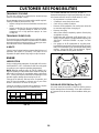
TO CHANGE ENGINE OIL (See Figs. 16 and 17)
Determine temperature range expected before oil change.
All oil must meet API service classification SF or SG.
• Be sure tractor is on level surface.
• Oil will drain more freely when warm.
• Catch oil in a suitable container.
• Remove oil fill cap/dipstick. Be careful not to allow dirt
to enter the engine when changing oil.
• Remove drain plug.
• After oil has drained completely, replace oil drain plug
and tighten securely.
• Refill engine with oil through oil fill dipstick tube. Pour
slowly. Do not overfill. For approximate capacity see
“PRODUCT SPECIFICATIONS” on page 3 of this
manual.
• Use gauge on oil fill cap/dipstick for checking level.
Insert dipstick into the tube and rest the oil fill cap on the
tube. Do not thread the cap onto the tube when taking
reading. Keep oil at “FULL” line on dipstick. Tighten
cap onto the tube securely when finished.
OIL FILL
CAP/DIPSTICK
OIL
DRAIN
PLUG
FIG. 17
AIR
SCREEN
FIG. 16
CLEAN AIR SCREEN (See Fig. 17)
Air screen must be kept free of dirt and chaff to prevent
engine damage from overheating. Clean with a wire brush
or compressed air to remove dirt and stubborn dried gum
fibers.

19
CUSTOMER RESPONSIBILITIES
CLEAN AIR INTAKE/COOLING AREAS
To insure proper cooling, make sure the grass screen,
cooling fins, and other external surfaces of the engine are
kept clean at all times.
Every 100 hours of operation (more often under extremely
dusty, dirty conditions), remove the blower housing and
other cooling shrouds. Clean the cooling fins and external
surfaces as necessary. Make sure the cooling shrouds are
reinstalled.
NOTE: Operating the engine with a blocked grass screen,
dirty or plugged cooling fins, and/or cooling shrouds re-
moved will cause engine damage due to overheating.
ENGINE OIL FILTER
Replace the engine oil filter every season or every other oil
change if the tractor is used more than 100 hours in one
year.
MUFFLER
Inspect and replace corroded muffler and spark arrester (if
equipped) as it could create a fire hazard and/or damage.
SPARK PLUGS
Replace spark plugs at the beginning of each mowing
season or after every 100 hours of operation, whichever
occurs first. Spark plug type and gap setting are shown in
“PRODUCT SPECIFICATIONS” on page 3 of this manual.
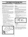
IN-LINE FUEL FILTER (See Fig. 19)
The fuel filter should be replaced once each season. If fuel
filter becomes clogged, obstructing fuel flow to carburetor,
replacement is required.
• With engine cool, remove filter and plug fuel line
sections.
• Place new fuel filter in position in fuel line with arrow
pointing towards carburetor.
• Be sure there are no fuel line leaks and clamps are
properly positioned.
• Immediately wipe up any spilled gasoline.
FIG. 19
FUEL FILTER
CLAMP
CLAMP
CLEANING
• Clean engine, battery, seat, finish, etc. of all foreign
matter.
• Keep finished surfaces and wheels free of all gasoline,
oil, etc.
• Protect painted surfaces with automotive type wax.
We do not recommend using a garden hose to clean your
tractor unless the electrical system, muffler, air filter and
carburetor are covered to keep water out. Water in engine
can result in a shortened engine life.
AIR FILTER (See Fig. 18)
Your engine will not run properly using a dirty air filter.
Clean the foam pre-cleaner after every 25 hours of opera-
tion or every season. Service paper cartridge every 100
hours of operation or every season, whichever occurs first.
Service air cleaner more often under dusty conditions.
• Loosen knob and remove cover.
TO SERVICE PRE-CLEANER
• Slide foam pre-cleaner off cartridge.
• Wash it in liquid detergent and water.
• Squeeze it dry in a clean cloth.
• Saturate it in engine oil. Wrap it in clean, absorbent
cloth and squeeze to remove excess oil.
TO SERVICE CARTRIDGE
• Remove nut and cartridge plate.
• Gently tap the flat side of the paper cartridge to dis-
lodge dirt. Do not wash the paper cartridge or use
pressurized air, as this will damage the cartridge.
Replace a dirty, bent, or damaged cartridge.
• Reinstall the pre-cleaner (cleaned and oiled) over the
paper cartridge.
• Check rubber seal for damage and proper position
around stud. Replace if necessary.
• Reassemble air cleaner, cartridge plate, and nut.
• Reinstall air cleaner cover and secure by tightening
knob.
NUT
RUBBER
SEAL
CARTRIDGE
FOAM
PRE-CLEANER
CARTRIDGE
PLATE
KNOB
FIG. 18

SERVICE AND ADJUSTMENTS
20
CAUTION: BEFORE PERFORMING ANY SERVICE OR ADJUSTMENTS:
• Depress clutch/brake pedal fully and set parking brake.
• Place motion control lever in neutral (N) position.
• Place attachment clutch in “DISENGAGED” position.
• Turn ignition key “OFF” and remove key.
• Make sure the blades and all moving parts have completely stopped.
• Disconnect spark plug wire from spark plug and place wire where it cannot come in contact with
plug.
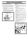
TO LEVEL MOWER HOUSING
Adjust the mower while tractor is parked on level ground or
driveway. Make sure tires are properly inflated (See
“PRODUCT SPECIFICATIONS” on page 3 of this manual).
If tires are over or underinflated, you will not properly adjust
your mower.
SIDE-TO-SIDE ADJUSTMENT (See Figs. 20 and 21)
• Raise mower to its highest position.
• Measure height from bottom of deck curl to ground
level at front corners of mower. Distance “A” on both
sides of mower should be the same.
• If adjustment is necessary, make adjustment on one
side of mower only.
• To raise one side of mower, tighten lift link adjustment
nut on that side.
• To lower one side of mower, loosen lift link adjustment
nut on that side.
NOTE: Each full turn of adjustment nut will change mower
height about 3/16".
• Recheck measurements after adjusting.
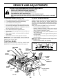
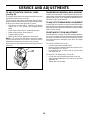
TO REMOVE MOWER (See Fig. 20)
• Place attachment clutch in “DISENGAGED” position.
• Turn height adjustment knob to lowest setting.
• Lower mower to its lowest position.
• Remove retainer spring holding anti-swaybar to chas-
sis bracket and disengage anti-swaybar from bracket.
• Remove retainer springs from suspension arms at
deck and disengage arms from deck.
• Raise attachment lift to its highest position.
• Remove two retainer springs from each front link and
remove links.
• Slide mower forward and remove belt from electric
clutch pulley.
• Slide mower out from under right side of tractor.
IMPORTANT: IF AN ATTACHMENT OTHER THAN THE
MOWER DECK IS TO BE MOUNTED ON THE TRACTOR,
REMOVE THE FRONT LINKS.
TO INSTALL MOWER
Follow procedure described in “INSTALL MOWER AND
DRIVE BELT” in the Assembly section of this manual.
FRONT
SUSPENSION
BRACKET
FRONT
SUSPENSION
BRACKET
RETAINER
SPRINGS
LIFT
LINKS
RETAINER
SPRING
ADJUSTMENT
NUTS
SUSPENSION
ARMS
CHASSIS
BRACKET
FRONT MOWER
BRACKET
ELECTRIC
CLUTCH
PULLEY
ANTI-SWAY
BAR
RETAINER
SPRINGS
FRONT
LINKS
FRONT MOWER
BRACKET
FIG. 20
FIG. 21
BOTTOM
OF CURL
BOTTOM
OF CURL
A
A
GROUND LINE
Page is loading ...
Page is loading ...
Page is loading ...
Page is loading ...
Page is loading ...
Page is loading ...
Page is loading ...
Page is loading ...
Page is loading ...
Page is loading ...
Page is loading ...
Page is loading ...
Page is loading ...
Page is loading ...
Page is loading ...
Page is loading ...
Page is loading ...
Page is loading ...
Page is loading ...
Page is loading ...
Page is loading ...
Page is loading ...
Page is loading ...
Page is loading ...
Page is loading ...
Page is loading ...
Page is loading ...
Page is loading ...
Page is loading ...
Page is loading ...
Page is loading ...
Page is loading ...
Page is loading ...
Page is loading ...
Page is loading ...
Page is loading ...
-
 1
1
-
 2
2
-
 3
3
-
 4
4
-
 5
5
-
 6
6
-
 7
7
-
 8
8
-
 9
9
-
 10
10
-
 11
11
-
 12
12
-
 13
13
-
 14
14
-
 15
15
-
 16
16
-
 17
17
-
 18
18
-
 19
19
-
 20
20
-
 21
21
-
 22
22
-
 23
23
-
 24
24
-
 25
25
-
 26
26
-
 27
27
-
 28
28
-
 29
29
-
 30
30
-
 31
31
-
 32
32
-
 33
33
-
 34
34
-
 35
35
-
 36
36
-
 37
37
-
 38
38
-
 39
39
-
 40
40
-
 41
41
-
 42
42
-
 43
43
-
 44
44
-
 45
45
-
 46
46
-
 47
47
-
 48
48
-
 49
49
-
 50
50
-
 51
51
-
 52
52
-
 53
53
-
 54
54
-
 55
55
-
 56
56


Ask a question and I''ll find the answer in the document
Finding information in a document is now easier with AI
Related papers
-
Husqvarna LTH130 User manual
-
-
-
-
-
-
-
-
-

