Samsung NS035NHXEA User manual
- Category
- Split-system air conditioners
- Type
- User manual
This manual is also suitable for

E-1
ENGLISH

E-2
Contents
SAFETY PRECAUTIONS . . . . . . . . . . . . . . . . . . . . . . . . . . . . . . . . . . . . . . . . . . . . . . . . . . 3
PREPARING FOR INSTALLATION
Choosing the Installation Location . . . . . . . . . . . . . . . . . . . . . . . . . . . . . . . . . . 5
Accessories . . . . . . . . . . . . . . . . . . . . . . . . . . . . . . . . . . . . . . . . . . . . . . . . . . . . . . . . . 6
INSTALLING THE AIR CONDITIONER
Fixing the Installation Plate . . . . . . . . . . . . . . . . . . . . . . . . . . . . . . . . . . . . . . . . . 7
Connecting the Assembly Cable . . . . . . . . . . . . . . . . . . . . . . . . . . . . . . . . . . . . 8
Installing and Connecting the Assembly Pipe of the Indoor Unit . . . 10
Purging the Indoor Unit . . . . . . . . . . . . . . . . . . . . . . . . . . . . . . . . . . . . . . . . . . . 11
Cutting or Extending the Pipe . . . . . . . . . . . . . . . . . . . . . . . . . . . . . . . . . . . . . . 12
Installing and Connecting the Drain Hose of the Indoor Unit . . . . . . 13
Changing Direction of the Drain Hose . . . . . . . . . . . . . . . . . . . . . . . . . . . . . . 14
Assigning Address to Indoor Unit . . . . . . . . . . . . . . . . . . . . . . . . . . . . . . . . . . . 15
Additional Functions . . . . . . . . . . . . . . . . . . . . . . . . . . . . . . . . . . . . . . . . . . . . . . . . 15
COMPLETING THE INSTALLATION
Fixing the Indoor Unit in Place . . . . . . . . . . . . . . . . . . . . . . . . . . . . . . . . . . . . . . 16
Final Check and Trial Operation . . . . . . . . . . . . . . . . . . . . . . . . . . . . . . . . . . . . . 17
Providing Information for User . . . . . . . . . . . . . . . . . . . . . . . . . . . . . . . . . . . . . . 18

E-3
ENGLISH
You must install the product by qualified installer. If you install the product on your own or by unqualified
person, Samsung is not responsible for any damages which may occur due to incorrect installation.
Make sure to read the following safety precautions carefully before installation.
Make sure to observe the cautions specified in this manual.
Conduct a test run of the unit after installation and then explain all system functions to the owner.
The indications and meanings are as shown below.
WARNING
Hazards or unsafe practices that may result in severe personal injury or death.
Installation must be carried
out by a qualified installer.
Do not attempt to repair,
move, modify or reinstall the
unit on your own since such
act may cause fire, electric
shock or water leakage.
Install the unit in a place
where it is strong enough
to hold the product weight.
When installed in place
where it is not strong enough
to withhold the product
weight, the unit could fall
and cause injury.
The unit should be
installed in accordance
with the National Electrical
regulations. Check if the
voltage and the frequency of
the main power supply are
those required for the unit
to be installed and check the
connection. Avoid the use of
an extension cord and do not
share the power outlet with
other appliances. Incomplete
connection, defective
insulation or exceeding the
permissible current may
cause electric shock or fire.
Use the specified wires to
connect the indoor and
outdoor units securely and
attach the wires firmly to the
terminal block connecting
sections so that the pressure
is not applied to the sections.
Inappropriate connection
and fixing could cause fire.
Attach the electrical cover to
the indoor and outdoor unit
securely without any gaps.
If there are any gaps, there is
potential risk of fire or electric
shock due to dust or water.
Make sure to use the part
provided or specified parts for
the installation work. The use
of defective parts could cause
an injury or leakage of water
due to a fire, an electric shock,
the unit falling, etc.
Make sure that the
refrigerant gas does not
leak after completing the
installation.
If the refrigerant gas of
the indoor unit leaks and
comes into contact with the
fan heater, space heater or
stove, harmful gas will be
generated.
Ensure that the national
safety code requirements
have been followed for the
main supply circuit. Ensure
that a proper ground wire is
in place.
Do not connect the ground
to a gas pipe, water pipe,
lightning rod or telephone
grounding. Defective
grounding could cause
electric shock.
Do not install the unit in a
place with direct sunlight,
dangerous substances
or where it is exposed to
inflammable gas leakage
to prevent explosion, fire or
personal injury.
Perform the installation
securely referring to
the installation manual.
Incomplete installation
could cause personal injury
due to fire, electric shock
and water leakage or from
the unit falling.
Before connecting the
power plug and power
receptacle check for dust,
loose or blocked. Make sure
that plug is fully inserted.
Dusted power plug,
blocked or loosened power
receptacle may cause fire
or electric shock. Exchange
the power receptacle if it is
loose.
Check first the following
situations before starting
the operation during the
installation.
- The pipe must be properly
connected and make sure
there is no leakage.
- Service valves must be open.
If compressor is operated
with the service valve
closed, excessive pressure
may damage parts of the
compressor.
If leakage occurs on any of
the connection, air inflow
may also cause excessive
pressure that could lead to
explosion.
Safety Precautions
Keep this installation manual together with the user’s manual in a handy place so that you can find it whenever
you need to see it after reading this manual thoroughly.
Make sure you read this ‘Safety Precautions’ carefully before installing the product.
Safety Precautions states information that is important to your safety matters. Please follow the instructions
carefully.
WARNING
Hazards or unsafe practices that may result in severe personal injury or death.
CAUTION
Hazards or unsafe practices that may result in minor personal injury or property damage.
Follow IEC (International Electrotechnical Commission) standards for the power input and
ISO (International Standards Organization) standards for input current.

E-4
Safety Precautions (Continued)
CAUTION
Hazards or unsafe practices that may result in minor personal injury or property
damage.
Perform the drainage/piping
work securely according to
the installation manual. If not,
water could drop from the
unit and household goods
could get wet and damaged.
Fasten a flare nut with a
torque wrench as specified
in this installation manual.
When fastened too tight,
a flare nut may break after
a long period of time and
cause refrigerant leakage.
Wear thick gloves during the
installation process.
If not, personal injury
may occur due to the air
conditioner parts.
Be careful not to touch
the outdoor unit inlet or
aluminium pins. You may get
personal injury.
The air conditioner should be
used only for the applications
for which it has been
designed: the indoor unit is
not suitable to be installed in
areas used for laundry.
When installing the indoor
unit, use a stable stool and
watch your steps carefully.
To prevent injury when
accidentally touching the
indoor unit fan, install the
indoor unit at least 2.5m
above the floor level.
Our units must be installed in
compliance with the spaces
indicated in the installation
manual to ensure either
accessibility from both sides
or ability to perform routine
maintenance and repairs. The
units’ components must be
accessible and that can be
disassembled in conditions
of complete safety either for
people or things.
For this reason, where it is
not observed as indicated
into the Installation Manual,
the cost necessary to reach
and repair the unit (in safety,
as required by current
regulations in force) with
slings, trucks, scaffolding or
any other means of elevation
won’t be considered
in-warranty and charged to
end user.
Do not install the outdoor
unit in a place where
animals could live. If an
animal get contact with the
electric parts, damage or
fire may occur. In addition
ask the customer to
maintain a clean installation
place around it.
Check the unit for damage
that may have taken place
during transportation and do
not install or use damaged
equipment.
After completing the
installation run the trial
operation. If no error occurs,
explain to the customer
how to use and clean the air
conditioner according to the
user’s manual. In addition
give the installation manual
and the user’s manual to the
customer.
All of the manufacturing
and packaging material
used for your new appliance
are compatible with the
environment and can be
recycled.
Dispose of the packaging
material in accordance with
the local requirements.
This product is an air
conditioning system and
contains a coolant that must
be recovered and disposed
of in an appropriate way by
qualified personnel. At the
end of the life cycle, take
it to a proper recycling or
disposal center or return it to
the dealer so that it can be
disposed correctly.
WARNING
Hazards or unsafe practices that may result in severe personal injury or death.
Stop the compressor before
disconnecting the refrigerant
pipe for pump-down
operation. If you disconnect
the refrigerant pipe while
compressor is operating with
service valve open, air inflow
will cause excessive pressure
in the refrigerant cycle that
could lead to explosion and
personal injury.
Do not assemble the power
cord on your own, use two
cables together to extend
the cable length or tangle
the cable. Bad connection,
isolation and over voltage may
cause fire or electric shock.
Make sure to turn off the
main power when setting
up the indoor unit electrical
circuit or power cords. There
is a risk of electric shock.
Make sure that proper
circuit breaker and safety
switches are installed.
Install a ground leakage
breaker depending on the
installation place(where it is
humid). If not, it may cause
electric shock.
Do not install the unit by
yourself (owners). Incorrect
installation of the unit could
cause injury due to fire,
electric shock and water
leakage or from the unit
falling. Consult a dealer or a
qualified installer.
Use the unit on a single
outlet circuit. Do not share
the power outlet with other
appliances.
Obtain the consent by a
qualified installer before
connecting the unit to the
power supply system.

E-5
ENGLISH
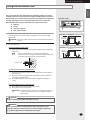
Choosing the Installation Location
PREPARING FOR INSTALLATION
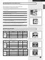
Observe the clearances and maximum lengths as seen in the picture below when installing the air conditioner.
125 mm
or more
300 mm or more
125 mm
or more
600 mm
minimum
300 mm
minimum
300 mm
minimum
600 mm
minimum
‘L’ meters maximum
total pipe length
Wrap the refrigerant pipes and the drain
hose with the absorbent pad and vinyl
tape. Refer to page 15 for further details.
You can select the direction
of draining. (left or right)
‘H’ meters maximum
total pipe Height
The appearance of the unit may be different from the diagram depending on the model.
Main power switch
Model L H
26
20 15
35
20 15
52
50 30
70
50 30
Make at least one round:
It will reduce noise and vibration
CAUTION:
3m as minimum pipe length.
It will reduce noise and vibration.
Indoor Unit Outdoor Unit
Where airflow is not blocked
Where cool air can be distributed throughout the room
Install the refrigerant piping length and the height
difference of both indoor and outdoor units as
indicated in the installation diagram
Wall that prevents vibration and is strong enough to hold the
product weight
Out of the direct sunlight
1m or more away from the TV or radio (to prevent the screen
from being distorted or noise from being generated)
As far away as possible from the fluorescent and incandescent
lights (so that the remote control can be operated well)
A place where the air filter can be replaced easily
Where it is not exposed to strong wind
Well ventilated and dustless places
Out of the direct sunlight and rain
Where neighbors are not annoyed by operation sound or hot air
Solid wall or support that prevents vibration and is strong
enough to hold the product weight
Where there is no risk of flammable gas leakage
When installing the unit at a high place be sure to fix the unit legs
3m or more away from the TV or radio (to prevent the screen
from being distorted or noise from being generated)
Install the unit horizontally
Place where drained water does not become any problem.
Place with no plants (especially climbing plants) and where
small animal can not access.
Avoid the following places to prevent malfunction of the unit
- Where there is machine oil - Salty environment such as seaside areas
- Where sulfide gas exists - Other special atmosphere areas
CAUTION

E-6
Accessories
PREPARING FOR INSTALLATION
The following accessories are supplied with the air conditioner:
Note
The number of each accessory is indicated in parentheses.
Note
If these accessories are supplied, they will be in the accessory box.
General Tools
Batteries for
Remote Control (2)
User’s Manual (1)
The following connection accessories are optional. If they are not supplied, you should obtain them before
installing the air conditioner.
Installation
Manual (1)
Remote Control (1)
Tools required for installation
Tools for test operations
Accessories in the Indoor Unit Case
Vacuum Pump(Backward flowing prevention) Manifold Gauge Stud Finder
Torque Wrench Pipe Cutter Reamer Pipe Bender
Spirit Level Screw Driver Spanner Drill
L Wrench Measuring Tape
Thermometer Resistance Meter Electroscope
Installation Plate (1)
PE T3 Foam Tube
Insulation (1)
Vinyl Tape (2)
3-wire
Power Cable
2-wire
Assembly Cable
Pipe Clamps A (3) Pipe Clamps B (3) Cement Nail (6) M4 x 25
Tapped Screws (6)
Drain Hose,
length 2m (1)
Putty 100g (1)
Assembly Pipe Indoor Unit
26/35/52/70
: Ø6.35mm (1)
26/35
: Ø9.52mm (1)
52
: Ø12.70mm (1)
70
: Ø15.88mm (1)

E-7
ENGLISH
Fixing the Installation Plate
INSTALLING THE AIR CONDTIONER
120
72
68
72
(Unit : mm)
140
34
68
34
(Unit : mm)
26/35
52/70
Pipe hole
(
Ø65mm)
Pipe hole
(
Ø65mm)
B
A
D
C
D
You can select the direction of the drain hose depending on where you want to
install the indoor unit. Therefore before fixing the installation plate to a wall or a
window frame, you must determine the position of the 65mm hole through which
the cable, pipe and hose pass to connect the indoor unit to the outdoor unit.
When facing the wall, the pipe and cable can be connected from the:
Right (A)
Left (B)
Underside_right (C)
Rear_right or left (D)
1
Determine the position of the pipe and drain hose hole as seen in the picture
and drill the hole with an inner diameter of 65mm so that it slants slightly
downwards.
CAUTION
Make sure to drill only one hole after choosing the direction of
the pipe.
2
Fix the indoor unit.
If you fix the indoor unit on a wall
(1) Fix the installation plate to the wall giving attention to the weight of the
indoor unit.
Note
If you mount the plate to a concrete wall using plastic
anchors, make sure that gaps between the wall and the plate,
created by projected anchor, is less than 20mm.
Wall
<20mm
Plastic Anchor
If you fix the indoor unit on a window frame
(1) Determine the positions of the wooden uprights to be attached to the
window frame.
(2) Attach the wooden uprights to the window frame giving attention to
the weight of the indoor unit.
(3) Attach the installation plate to the wooden upright using tapping
screws.
If you fix the indoor unit on a gypsum board
(1) Use stud finder to find out locations of the studs.
(2) Fix the plate hanger on two studs.
CAUTION
Search for other spots if there are less than two studs, or
the distance between the studs are different from the
plate hanger.
Direction of pipe
Fix the installation plate without incling to one side.
CAUTION
Make sure that a wall can withstand the weight of the product. If you
install the product in a place where it is not strong enough to withstand
the product weight, the unit could fall and cause injury.
WARNING

E-8
Connecting the cable
When you install the unit, make first refrigerant connections and then elec-
trical connections. Connect the air conditioner to grounding system before
performing the electrical connection. If unit is uninstalled first disconnect
electrical cables, then refrigerant connections.
1
Extend the assembly cable if necessary.
CAUTION
Do not connect two or more different cables to extend the
length. It may cause fire.
2
Open the front grille.
3
Remove the screw securing the connector cover.
4
Pass the assembly cable through the rear of the indoor unit and connect the
assembly cable to terminals
. (Refer to the picture in page 9.)
Note
Each wire is labeled with the corresponding terminal number.
5
Pass the other end of the cable through the 65mm hole in the wall.
6
Close the connector cover by tightening the screw carefully.
7
Close the front grille.
8
Remove the terminal board cover on the side of the outdoor unit.
Connecting the Assembly Cable
Screw
Torque(kgf
.
cm)
Unfasten Torque Tighten Torque
M4 17~30 25~40
M5 20~35 30~50
INSTALLING THE AIR CONDTIONER

E-9
ENGLISH
The terminal is connected too firmly , the terminal may be damaged.
Connect the wires firmly so that wires can not be pulled out easily.
(If they are loose, it could cause burn-out of the wires.)
Connect the wires according to color codes, referring to the wiring
diagram.
WARNING
9
Connect the cables to the terminals as seen in the picture.
Note
Each wire is labeled with the corresponding terminal number.
10
Connect the grounding conductor to the grounding terminals.
11
Close the terminal board cover by tightening the screw carefully.
12
Connect the power cable to the indoor unit.
Note
In Russia and Europe, consult with the supply authority to
determine the supply system impedance before installation.
1(L)
2(N)
F12(N)1(L)
F2
1
2
1 2
F1 F2
F1
F2
F1 F2
Indoor unit
Outdoor unit
Indoor unit
Outdoor unit
CAUTION
End of the wire must be circular.
After connecting the cables, make sure terminal numbers on
the indoor/outdoor unit matches.
Screws on terminal block must not be unscrewed with the
torque less than 12kgf•cm
.
Connecting the Assembly Cable
Earth
terminal
INSTALLING THE AIR CONDTIONER

E-10
INSTALLING THE AIR CONDTIONER
Installing and Connecting the Assembly Pipe of the Indoor Unit
Connect indoor and outdoor units with field-supplied copper pipes by means
of flare connections. Use insulated seamless refrigeration grade pipe only, (Cu
DHP type according to ISO1337), degreased and deoxidized, suitable for op
-
erating pressures of at least 4200 kPa and for burst pressure of at least 20700
kPa. Under no circumstances must sanitary type copper pipe be used.
There are 2 refrigerant pipes of different diameters:
The smaller one is for the liquid refrigerant
The larger one is for the gas refrigerant
A short pipe is already fitted to the air conditioner. You may need to extend the
pipe using the assembly pipe (optional).
The connection procedure for the refrigerant pipe varies according to the exit
position of the pipe when facing the wall:
Right(A)
Left(B)
Underside(C)
Rear
1
Cut out the appropriate knock-out piece (A, B, C) on the rear of the indoor unit
unless you connect the pipe directly from the rear.
2
Smooth the cut edges.
3
Remove the protection caps of the pipes and connect the assembly pipe
to each pipe. Tighten the nuts first with your hands, and then with a torque
wrench, applying the following torque:
Outer Diameter Thickness Torque (kgf•cm)
ø6.35 mm 0.8mm 140~170
ø9.52 mm 0.8mm 250~280
ø12.70 mm 0.8mm 380~420
ø15.88 mm 1.0mm 440~480
ø19.05 mm 1.0mm 990~1210
ø22.23 mm 1.0mm 990~1210
Note
If you want to shorten or extend the pipes, refer to page 12.
4
Cut off the remaining foam insulation.
5
If necessary, bend the pipe to fit along the bottom of the indoor unit.
Then pull it out through the appropriate hole.
The pipe should not project from the rear of the indoor unit.
The bending radius should be 100 mm or more.
6
Pass the pipe through the hole in the wall.
7
For further details on how to connect to the outdoor unit and purge the air,
refer to page 11.
B
A
C
Tighten the flare nut with torque wrench according to specified method.
If the flare nut is over-tightened, the flare may break and cause
refrigerant gas leakage.
DO NOT WALL UP THE PIPE CONNECTION !
All refrigerant pipe connection must be easy accessible and serviceable.
CAUTION

E-11
ENGLISH
INSTALLING THE AIR CONDTIONER
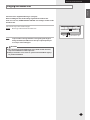
The indoor unit is supplied with inert gas (nitrogen).
Before installing the unit, check if nitrogen gas flow out of indoor unit.
If this one isn’t true, DO NOT INSTALL THE UNIT since leakage could be inside
the indoor unit.
Unscrew the caps at the end of each pipe.
Result
: All inert gas exhausts from the indoor unit.
Note
To prevent dirt or foreign substances from getting into the pipes
during installation, do NOT remove the caps completely until you
are ready to connect the pipes.
The remaining air in the Refrigeration cycle, which contains moisture,
may cause malfunction on the compressor.
Always contact the service center or a professional installation agency
for product installation.
CAUTION
Unscrew the capsPipes
Purging the Indoor Unit

E-12
INSTALLING THE AIR CONDTIONER
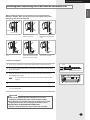
Cutting or Extending the Pipe
1
Make sure that you have all the required tools (pipe cutter, reamer, flaring tool
and pipe holder)
.
2
If you want to shorten the pipe, cut it using a pipe cutter, ensuring that the cut
edge remains at 90° with the side of the pipe (see below examples of correct
and incorrect cut edges
).
Oblique Rough Burr
3
To prevent a gas leak, remove all burrs at the cut edge of the pipe using a reamer.
CAUTION
Face the pipe down while removing the burrs to make sure
that burrs do not get in to the pipe.
4
Put a flare nut slightly into the pipe and modify the flare.
Outer Diameter (D)
Thickness
Depth (A)
ø6.35 mm 0.8mm 1.3 mm
ø9.52 mm 0.8mm 1.8 mm
ø12.70 mm 0.8mm 2.0 mm
ø15.88 mm 1.0mm 2.2 mm
ø19.05 mm 1.0mm 2.2 mm
ø22.23 mm 1.0mm 2.2 mm
5
Check if you flared the pipe correctly (see examples of incorrectly flared pipes
below).
Correct
Uneven
Thickness
Cracked
Damaged
Surface
Inclined
6
Align the pipes to connect them easily. Tighten the flare nuts first with your
hands, and then with a torque wrench, applying the following torque:
Outer Diameter Thickness Torque (kgf•cm)
ø6.35 mm 0.8mm 140~170
ø9.52 mm 0.8mm 250~280
ø12.70 mm 0.8mm 380~420
ø15.88 mm 1.0mm 440~480
ø19.05 mm 1.0mm 990~1210
ø22.23 mm 1.0mm 990~1210
Note
Excessive torque can be cause of gas leakage.
In case brazing the pipe, the nitrogen gas must be blown into the pipe
(50 Pa). The joint must be accessible and serviceable.
Pipe cutter
Pipe
Indoor outlet pipe Connecting pipe
Flare nut
Tighten the flare nut with torque wrench according to specified method.
If the flare nut is over-tightened, the flare may break and cause refrigerant
gas leakage.
CAUTION
Pipe Flare

E-13
ENGLISH
INSTALLING THE AIR CONDTIONER
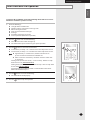
Installing and Connecting the Drain Hose of the Indoor Unit
When installing the drain hose for the indoor unit, check if condensation
draining is adequate. When passing the drain hose through the 65-mm hole
drilled in the wall, check the followings:
Drain hose installation:
1
If necessary, connect the 2-meter extension drain hose to the drain hose.
2
If you use the extension drain hose, insulate the inside of the extension drain
hose with a shield.
3
Fit the drain hose into 1 of 2 drain hose holes, then fix the end of the drain
hose tightly with a clamp.
Note
If you do not use the other drain hose hole, block it with a rubber
stopper.
4
Pass the drain hose under the refrigerant pipe, keeping the drain hose tight.
5
Pass the drain hose through the hole in the wall. Check if it slants downwards
as seen in the picture.
Shield
Drain hose Extension drain hose
Make sure the installed direction of the drain hose is correct.
Inadequate installation may cause condensate water leakage.
If the drain hose is routed inside the room, insulate the hose so that
dripping condensation does not damage the furniture or floors.
DO NOT WALL UP THE DRAIN HOSE CONNECTION !
Drain hose connection must be easy accessible and serviceable
CAUTION
The drain hose must not be
bent.
Keep a clearance of at least
5cm between the end of the
drain hose and the ground.
5cm
less
Do NOT place the end of the
drain hose in a hollow.
Ditch
The end of the drain hose
must NOT be placed under
water.
The drain hose must
NOT slant upwards.
Wall
Drain hose
Indoor unit
Drain hose hole

E-14
INSTALLING THE AIR CONDTIONER
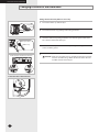
Changing Direction of the Drain Hose
Rubber cap
Drain pan outlet
Change the direction only when it is necessary.
1
Detach the rubber cap with the flyer.
2
Detach the drain hose by pulling it and turning to the left.
3
Insert the drain hose by fixing it with the screw into the groove of the drain
hose and the outlet of the drain pan.
4
Attach the rubber cap with a screwdriver by turning it to the right until it fixes
to the end of the groove.
5
Check for leakage on both side of the drain outlet.
CAUTION
Make sure the indoor unit is in upright position when you pour
water to check for leakage. Make sure that the water does not
overflow onto the electrical part.
Drain hose
Screw
hole
Screw
<Pour the water in direction of arrow>
Direction of the drained water

E-15
ENGLISH
INSTALLING THE AIR CONDTIONER
Assigning Address to Indoor Unit
Before installing the indoor unit, assign an address to the indoor
unit according to the air conditioning system plan.
1
Open the front grille by pulling on the tabs on the lower right and left sides of
the indoor unit.
2
Remove the screw securing the cover PCB.
3
Remove the cover PCB.
4
The address of the indoor unit is assigned by adjusting MAIN(SW02).
5
The MAIN address is for communication between the indoor unit and the
outdoor unit. Therefore, you must set it to operate the air conditioner properly.
6
It is required to set the RMC address if you install the wired remote controller
and/or the centralized controller.
7
If you install optional accessories such as the wired remote controller,
centralized controller, etc. see an appropriate installation manual.
8
Refer to the outdoor unit installation manual for the details.
SW02 MAIN
Additional Functions
Cover PCB
K5 K6 K7 K8
SW05
SW07
No. Function ON OFF
SW05
K1 External room sensor Not use Use
K2 Centralized controller Not use Use
K3 - - -
K4 - - -
No. Function ON OFF
SW0
6
K5
Indoor Temperature
Compensation for Heating Mode
+2°C +5°C
K6 - - -
K7 - - -
K8 - - -
No. Function ON OFF
SW0
7
K9 - - -
K10 - - -
K11 External control Not Use Use
K12 External Control Output Thermal ON Operation ON
K1 OFF
Heating mode : Setting temperature compensation value = 0°C
Thermo OFF
Fan OFF
SW06

E-16
Fixing the Indoor Unit in Place
COMPLETING THE INSTALLATION
After checking for gas leaks in the system, insulate the pipe, hose and cables.
Then place the indoor unit on the installation plate.
1
To avoid condensation problems, wrap foam insulation (as shown in the figure
A) on a part without insulation on the end of the pipes.
2
Wind the pipe, assembly cable and drain hose with vinyl tape.
3
Place the bundle (the pipe, assembly cable and drain hose) in the lower part of
the indoor unit carefully so it does not project from the rear of the indoor unit.
4
Hook the indoor unit to the installation plate and move the unit to the right
and left until it is securely in place.
CAUTION
Make sure pipe does not move when you install the indoor unit
on an installation plate.
5
Wrap the rest of the pipe with vinyl tape.
6
Attach the pipe to the wall using clamps (optional).
Installation plate
Connecting wires
Drain hose
Connecting
pipes
Vinyl tape
Insulation
Pipes
<Figure A>
Perform the following work on the area where gas leak test was done priorly.

E-17
ENGLISH
COMPLETING THE INSTALLATION
Final Check and Trial Operation
To complete the installation, perform the following checks and tests to ensure
that the air conditioner operates correctly.
1
Check the followings:
Strength of the installation site
Tightness of pipe connection to detect gas leak
Electric wiring connection
Heat-resistant insulation of the pipe
Drainage
Grounding conductor connection
Correct operation (follow the steps below)
2
Press the button and check the following:
The indicator on the indoor unit lights up.
The airflow blade opens and the fan gears up for operation.
3
Press the button to select Cool or Heat mode.
In Cool mode, use Temp or button and set the temperature at 18°C.
In Heat mode, use Temp or button and set the temperature at 30°C.
Note
Approximately 3~5 minutes later, outdoor unit will start to
operate and the Cool or Warm air will blow out.
After 12 minutes of stationary condition check the indoor unit
air treatment:
Cooling mode (indoor unit check) --> Inlet air temp. - Outlet air temp:
From
10°K to 12°K ( indicative delta T)
Heating mode (indoor unit check) --> Outlet air temp. - Inlet air temp: From
11°K to 14°K (indicative delta T
)
In heating mode, the indoor fan motor can remain off to avoid cold air
blown into conditioned space.
4
Press the button and check the following:
The airflow blades work properly.
5
Press the button to stop the operation.

E-18
After finishing the installation of the air conditioner, explain the followings to
the user:
1
How to start and stop the air conditioner
2
How to select the modes and functions
3
How to adjust the temperature and the fan speed
4
How to adjust the airflow direction
5
How to set the timers
6
How to clean and replace the filters
Note
When you complete the installation successfully, hand over
the User’s Manual and this Installation Manual to the user for
storage in a handy and safe place.
Providing Information for User
COMPLETING THE INSTALLATION


Page is loading ...
-
 1
1
-
 2
2
-
 3
3
-
 4
4
-
 5
5
-
 6
6
-
 7
7
-
 8
8
-
 9
9
-
 10
10
-
 11
11
-
 12
12
-
 13
13
-
 14
14
-
 15
15
-
 16
16
-
 17
17
-
 18
18
-
 19
19
-
 20
20
-
 21
21


Samsung NS035NHXEA User manual
- Category
- Split-system air conditioners
- Type
- User manual
- This manual is also suitable for
Ask a question and I''ll find the answer in the document
Finding information in a document is now easier with AI
Related papers
Other documents
-
Daikin FTK12NMVJU Installation guide
-
Hitachi RAM-53QH5 User manual
-
Toshiba RAV-SM561AT-E User manual
-
-
-
-
-
-
-