GE MULTILIN IAV51D User manual
- Category
- Power generators
- Type
- User manual

GEK-45404F
MULTILIN
GE Power Management
INSTRUCTIONS
OVERVOLTAGE RELAYS
TYPES IAV, 51D
K
52C
D
K
GE Power Management
205 Great Valley Parkway
Malvern, PA 19355, USA
Click here to get to our homepage:
http://www.gemultilin.com/

GEK-45404
2
DESCRIPTION................................................................................................................................................... 3
APPLICATION................................................................................................................................................... 4
RATINGS............................................................................................................................................................ 5
BURDENS.......................................................................................................................................................... 6
OPERATING CHARACTERISTICS................................................................................................................. 8
CONSTRUCTION.............................................................................................................................................. 9
RECEIVING, HANDLING, AND STORAGE ................................................................................................ 10
RECEIVING.................................................................................................................................................. 10
HANDLING.................................................................................................................................................. 10
STORAGE..................................................................................................................................................... 10
ACCEPTANCE TESTS.................................................................................................................................... 10
VISUAL INSPECTION ................................................................................................................................ 10
MECHANICAL INSPECTION..................................................................................................................... 11
ELECTRICAL TESTS.................................................................................................................................. 12
Drawout Relays - General.......................................................................................................................... 12
Power Requirements - General.................................................................................................................. 12
Pickup-voltage Test ................................................................................................................................... 12
Time-voltage Test...................................................................................................................................... 12
INSTALLATION.............................................................................................................................................. 13
INSPECTION................................................................................................................................................ 13
LOCATION................................................................................................................................................... 13
MOUNTING ................................................................................................................................................. 13
CONNECTIONS........................................................................................................................................... 13
GROUND CONNECTIONS......................................................................................................................... 13
OPERATION.................................................................................................................................................... 13
ADJUSTMENTS........................................................................................................................................... 14
Target and Seal-in Unit.............................................................................................................................. 14
Voltage Setting .......................................................................................................................................... 14
Time Setting............................................................................................................................................... 15
PERIODIC CHECKS AND ROUTINE MAINTENANCE.............................................................................. 15
MAINTENANCE.............................................................................................................................................. 15
DISK AND BEARINGS ............................................................................................................................... 15
CONTACT CLEANING............................................................................................................................... 16
SERVICING...................................................................................................................................................... 16
RENEWAL PARTS.......................................................................................................................................... 16
LIST OF ILLUSTRATIONS ............................................................................................................................ 17
Cover Photo(8043180)
These instructions do not purport to cover all details or variations in equipment nor provide for every possible
contingency to be met in connection with installation, operation or maintenance. Should further information be desired
or should particular problems arise which are not covered sufficiently for the purchaser's purposes, the matter should be
referred to the General Electric Company.
To the extent required the products described herein meet applicable ANSI, IEEE and NEMA standards; but no
such assurance is given with respect to local codes and ordinances because they vary greatly.
OVERVOLTAGE RELAYS
TYPES IAV51D, IAV51K, IAV52C, IAV52D, IAV52K

GEK-45404
3
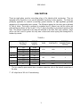
DESCRIPTION
These are single-phase, sensitive overvoltage relays of the induction disk construction. They are
equipped with a time dial so as to provide adjustable time delay in their operation. The relays are
principally applicable for sensitive overvoltage ground detection for high-impedance grounded
generators or for ungrounded power systems. The differences among the four relays are as indicated
in Table A below. Each relay is mounted in a standard size S1 drawout case and the outline and
panel drillings are shown in Figs. 14 and 15; Fig. 13 shows the outline for an external capacitor when
used. The internal connections of the relays are indicated in the table. Each relay contains a target
seal-in unit that is used to protect the relay main contacts and control spring from damage due to
breaker-trip current.
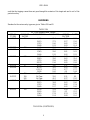
TABLE A
CONTINUOUS
RATING**
(VOLTS)
PICKUP
RANGE,
VOLTS
TAPS CONTACTS
INTERNAL
CONNECTIONS
FIGURE
IAV51D 115 10-40
199 16-64 YES 1NO 1
345 28-112
IAV51K 67 5.4-20 YES 1NO 2
IAV52C 115 9.2
199 16 NO 2NO* 3
345 28
IAV52D 199 16-64 YES 2NO* 4
IAV52K 67 5.4-20 YES 2NO* 5
* The two normally-open contacts have a common connection; refer to the internal connections of
the relay.
** All relays have a 360 volt 10 second rating.

GEK-45404
4
APPLICATION
These are single-phase, sensitive, time-delay overvoltage relays. They are principally applicable for
sensitive overvoltage ground detection for high-impedance grounded generators or for ungrounded
power systems. These relays all have a capacitor in series with the operating coil. For the IAV51K
and IAV52K relays, this capacitor is external to the relay because of its large size. The effect of the
capacitor is to tune the relay coil circuit so that the relay pickup on third harmonic (180Hz) voltage is
approximately eight times the relay pickup at 60 Hz. This is particularly important in overvoltage
ground detection for generators, since they produce a large third- harmonic component of voltage
during normal operation.
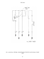
The external connection diagram for the IAV51K or the IAV52K relay for sensitive generator ground
detection is shown in Fig. 8. This is a typical protection scheme for a unit generator transformer
using a distribution transformer connected in the neutral with a resistor across the transformer
secondary. The IAV51K/52K relays are usually used for this application because they provide the
very sensitive 5.4 volt pickup rating. This enables the relay to detect a ground fault within a few
percent of the winding from the neutral. Since the power transformer and the station service
transformer in a unit generator transformer scheme are both connected in delta on the generator side,
coordination with other protection is virtually unnecessary and the ground relay used can be very
sensitive. Some time delay in relay operation is usually used to coordinate with fuses protecting
against faults on the secondary side of potential transformers that are normally connected to the
generator terminals. The usual practice is to use these relays to trip the generator breaker and shut
down the machine. If the relay is used only to sound an alarm when a ground fault is detected, the
application should be reviewed. It may be necessary to add another relay to provide ground
protection with good sensitivity simultaneously with a high continuous-voltage rating.
The resistor, shown in Fig. 8 connected across the broken delta secondary of the PT's, or alternatively
connected in series in the primary neutral connection, is usually required to prevent the occurrence of
ferro-resonance. This phenomenon could occur due to the interaction of the PT inductance with the
distributed capacitance-to-ground of the primary power system.
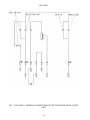
The external connection diagram for the IAV51D, 52D, or the IAV52C relay for ground-fault
detection on an ungrounded power system is shown in Fig. 9. The relay operates to detect the first
ground fault that occurs on the system, connections so that it can be removed before a second
ground occurs, causing a double phase-to-ground fault, which requires a service interruption. Since
the relay may be applied merely to sound an alarm in this application, it is necessary that it be
continuously rated for the full broken-delta voltage expected for a single phase-to-ground fault
located right at the potential transformers, or some automatic means must be employed to disconnect
the relay from the voltage supply.
When this fault occurs it is equivalent to shorting out one phase of the potential transformer primary.
The other two unfaulted phases of the PT primaries now have full phase-to-phase voltage applied
and their corresponding dJelta secondaries will be supplying √3 times their normal rated voltage.
The broken delta equivalent voltage will be these two voltages added in series at a 60
o
angle and the

GEK-45404
5
broken delta voltage will therefore be three times the normal delta phase-to-phase voltage with no
fault.
RATINGS
The operating-circuit ratings available are shown in Table I. The operating coil will stand rated
voltage continuously on any tap.
RELAY VOLTAGE RATINGS
60HZ 50HZ
IAV51D 115 115
199 199
345 345
IAV51K 67 67
IAV52C 115 115
199 199
345 345
IAV52D 199
IAV52K 67 67
The current-closing rating of the contacts is 30 amperes for voltage not exceeding 250 volts. The
current-carrying ratings are affected by the selection of the tap on the seal-in coil, as indicated in
Table II.
TABLE II
FUNCTION AMPERES
2-Amp Tap 0.2-Amp Tap
Tripping Duty Carry
Continuously
30
3
0
0.3
The 2-ampere tap has a DC resistance of 0.13 ohms and a 60 cycle impedance of 0.53 ohms, while
the 0.2-ampere tap has a 7-ohm DC resistance and a 52-ohm 60 cycle impedance. The tap setting
used on the seal-in element is determined by the current drawn by the trip coil.
The 0.2-ampere tap is for use with trip coils that operate on currents ranging from 0.2 up to 2.0
amperes at the minimum control voltage. If this tap is used with trip coils requiring more than two
amperes, there is a possibility that the 7-ohm resistance will reduce the current to so low a value that
the breaker will not be tripped.
The 2-ampere tap should be used with trip coils that take 2 amperes or more at minimum control
voltage, provided the tripping current does not exceed 30 amperes at the maximum control voltage.
If the tripping current exceeds 30 amperes an auxiliary relay should be used, the connections being

GEK-45404
6
such that the tripping current does not pass through the contacts of the target and seal-in coil of the
protective relay.
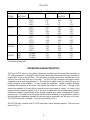
BURDENS
Burdens for the various relay types are give in Tables IIIA and B.
TABLE IIIA
60 - Cycle Burdens Rated Voltage
RELAY
TYPES
VOLTAGE
RATING
TAP**SETTING VOLT-AMPS POWER
FACTOR
WATTS
1AV51D 115 A(10) 31.4 0.33 10.2
B(15) 27.2 0.57 15.6
C(25) 19.0 0.82 15.6
D(40) 12.3 0.93 11.4
IAV51D 199 A(16) 32.0 0.31 9.9
IAV52D B(24) 27.9 0.56 15.6
C(40) 20.0 0.81 16.2
D(64) 13.2 0.92 12.2
IAV51D 345 A(28) 41.5 0.37 15.5
B(42) 35.0 0.62 21.6
C(70) 23.9 0.85 20.3
D(112) 13.6 0.95 12.9
IAV51K 67 A(5.4) 34.0 0.31 10.5
IAV52K B(7.5) 31.0 0.52 15.9
C(12.5) 23.1 0.77 17.7
D(20) 16.0 0.9 14.4
115 No Taps 24.2 0.21 5.0
IAV52C 199 No Taps 32.0 0.31 9.9
345 No Taps 41.5 0.37 15.5
1AV51D 115 A(10) 36.8 0.34 12.6
B(15) 30.8 0.62 19.0
C(25) 20.3 0.86 17.4
D(40) 12.7 0.95 12.0
IAV51D 199 A(16) 25.4 0.28 7.0
B(24) 23.1 0.5 11.5
C(40) 17.8 0.74 13.3
D(64) 12.4 0.88 11.0
TABLE IIIA (CONTINUED)

GEK-45404
7
50 - Cycle Burdens at Rated Voltages
RELAY
TYPES
VOLTAGE
RATING
TAP**SETTING VOLT-AMPS POWER
FACTOR
WATTS
IAV51D 345 A(28) 31.9 0.36 11.4
B(42) 28.3 0.56 15.8
C(70) 21.0 0.79 16.6
D(112) 12.8 0.93 11.9
IAV51K 67 A(5.4) 28.8 0.29 8.4
IAV52K B(7.5) 26.6 0.45 12.1
C(12.5) 21.1 0.71 14.9
D(20) 16.0 0.86 13.7
115 No Taps 25.0 0.41 10.1
IAV52C 199 No Taps 25.4 0.28 7.0
345 No Taps 31.9 0.36 11.4
**Minimum pickup volts
TABLE IIIB
60 - Cycle Burden at Rated Voltages
RELAY
TYPES
VOLTAGE
RATINGS
TAP**SETTINGS VOLT-AMPS POWER
FACTOR
WATTS
1AV51D 115 A(10) 0.46 0.99 0.46
B(15) 0.62 1.0 0.62
C(25) 0.96 1.0 0.96
D(40) 1.48 1.0 1.48
IAV51D 199 A(16) 0.41 0.94 0.38
IAV52D B(24) 0.56 0.98 0.55
C(40) 0.89 0.99 0.88
D(64) 1.38 1.0 1.37
IAV51D 345 A(28) 0.48 0.86 0.41
B(42) 0.66 0.95 0.62
C(70) 1.02 0.98 1.01
D(112) 1.4 0.99 1.4
IAV51K 67 A(5.4) 0.43 0.91 0.39
IAV52K B(7.5) 0.57 0.96 0.55
C(12.5) 0.92 0.98 0.91
D(20) 1.47 0.99 1.46
115 No Taps 0.36 0.78 0.28
IAV52C 199 No Taps 0.41 0.94 0.38
345 No Taps 0.48 0.86 0.41
TABLE IIIB

GEK-45404
8
50 - Cycle Burden at Rated Voltages
RELAY
TYPES
VOLTAGE
RATINGS
TAP**SETTINGS VOLT-AMPS POWER
FACTOR
WATTS
1AV51D 115 A(10) 0.52 0.98 0.52
B(15) 0.67 0.99 0.67
C(25) 1.0 1.0 1.0
D(40) 1.52 1.0 1.52
IAV51D 199 A(16) 0.32 0.85 0.27
B(24) 0.5 0.93 0.46
C(40) 0.83 0.97 0.81
D(64) 1.33 0.99 1.32
IAV51D 345 A(28) 0.39 0.96 0.37
B(42) 0.58 0.98 0.57
C(70) 0.96 0.99 0.95
D(112) 1.35 1.0 1.35
IAV51K 67 A(5.4) 0.38 0.91 0.34
IAV52K B(7.5) 0.52 0.95 0.5
C(12.5) 0.87 0.98 0.85
D(20) 1.42 0.99 1.41
115 No Taps 0.27 0.98 0.27
IAV52C 199 No Taps 0.32 0.85 0.27
345 No Taps 0.39 0.96 0.37
**Minimum pickup volts
OPERATING CHARACTERISTICS
The Type IAV51D relay is a low-pickup voltage relay normally used for ground fault protection on
AC rotating machines. It has single-circuit closing contacts that close when the voltage increases to
pickup value, as set on the tap block. The time delay in closing the contacts is determined by the
setting of the time dial at the top of the shaft. The IAV51D has a capacitor and tapped resistor
connected in series with the operating coil. The capacitor is added to tune the circuit, giving a low
pickup voltage at rated frequency. At rated voltage the operating U magnet is highly saturated,
increasing the impedance of the circuit, thus limiting the current to a safe value. The taps on the
resistor are connected to the tap block to provide a four-to-one range of pickup. As shown in the
typical external connection diagram, Fig. 8, this relay is connected to the machine neutral potential
transformer through a closed contact on the auxiliary tripping relay, hence is energized only when a
ground occurs. To obtain still-lower pickup than the normal calibration, it is permissible to insert an
inverted potential transformer between the machine neutral transformer and the relay coil circuit.
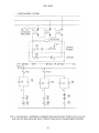
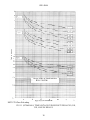
The IAV51D has a seal-in element. Time curves are shown in Fig. 11.
The IAV51K relay is similar to the IAV51D except that it has an external capacitor. Time curves are
shown in Fig. 11.

GEK-45404
9
The IAV52K relay is similar to the IAV51K except that it has two, instead of one, normally-open
contacts.
The IAV52C is a low-pickup, time-overvoltage relay with two normally-open contacts. It has a seal-
in element. It has a capacitor connected in series with the operating coil but, unlike the IAV51D
relay, it does not have a tapped resistor connected in series with the operating coil. The time-voltage
characteristics at the #1, #5, and #10 time-dial settings are the same as for the "A" taps of the
IAV51/52D and K relays shown in Fig. 11.
CONSTRUCTION
These relays are the induction disk construction. The disk is actuated by a potential operating coil on
a laminated U-magnet. The disk shaft carries the moving contact, which completes the trip or alarm
circuit when it touches the stationary contact or contacts. The disk shaft is restrained by a spiral
spring to give the proper contact-closing voltage, and its motion is retarded by permanent magnets
acting on the disk to give the correct time delay.
There is a seal-in unit mounted to the left of the shaft. This unit has its coil in series and its contacts
in parallel with the main contacts, such that when the main contacts close, the seal-in unit picks up
and seals in. When the seal-in unit picks up, it raises a target into view that latches up and remains
exposed until released by pressing a button beneath the lower-left corner of the cover.
The case is suitable for either surface or semi-flush panel mounting and an assortment of hardware is
provided for either mounting. The cover attaches to the case and also carries the reset mechanism
when one is required. Two of the cover screws have provision for a sealing wire.
The case has studs or screw connections at the bottom for the external connections. The electrical
connections between the relay units and the case studs are made through spring-backed contact
fingers mounted in stationary, molded inner and outer blocks, between which nests a removable
connecting plug that completes the circuits. The outer blocks, attached to the case, have the studs for
the external connections, and the inner blocks have the terminals for the internal connections.
The relay mechanism is mounted in a steel framework called the cradle and is a complete unit, with
all leads being terminated at the inner block. This cradle is held firmly in the case by a latch at the
top and the bottom and by a guide pin at the back of the case. The case and cradles are so contructed
that the relay cannot be inserted in the case upside down. The connecting plug, besides making the
electrical connections between the respective blocks of the cradle and case, also locks the latch in
place. The cover, which is fastened to the case by thumbscrews, holds the connecting plug in place.
To draw out the cradle from a single-ended case, the cover must first be removed. Then the
connecting plug can be drawn out. In so doing, the trip circuit is the first one opened, then the
voltage circuits are opened. After the connecting plug has been removed, the lower latch can be
released and the cradle easily drawn out. To replace the cradle, the reverse order should be followed.
The internal connections of the relays are shown in Figs. 3, 4, 5, 6, and 7.

GEK-45404
10
RECEIVING, HANDLING, AND STORAGE
RECEIVING
These relays, when not shipped as a part of a control panel, will be shipped in cartons designed to
protect them against damage. Immediately upon receipt of the relay, an examination should be made
for any damage sustained during shipment. If injury or damage resulting from rough handling is
evident, a damage claim should be filed at once with the transportation company and the nearest
General Electric Sales Office should be notified promptly.
HANDLING
Reasonable care should be exercised in unpacking the relay in order that none of the parts are injured
nor the adjustments disturbed.
STORAGE
If the relays are not to be installed immediately, they should be stored in their original cartons in a
place that is free from moisture, dust, and metallic chips. Foreign matter collected on the outside of
the case may find its way inside when the cover is removed and cause trouble in the operation of the
relay.
ACCEPTANCE TESTS
Immediately upon receipt of the relay an inspection and acceptance test should be made to make sure
that no damage has been sustained in shipment and that the relay calibrations have not been
disturbed.
VISUAL INSPECTION
Check the nameplate stamping to make sure that the model number and rating of the relay agree with
the requisition.
Remove the relay from its case and check that there are no broken or cracked molded parts or other
signs of physical damage, and that all screws are tight.

GEK-45404
11
CAUTION:
Every circuit in the drawout case has an auxiliary brush. It is especially important on current
circuits and other circuits with shorting bars that the auxiliary brush be bent high enough to
engage the connecting plug or test plug before the main brushes do. This will prevent Current
Transformer (CT) secondary circuits from being opened.
MECHANICAL INSPECTION
On relays that have time dials, the dials will be set at zero before the relay leaves the factory. It is
necessary to change this setting to open the relay contacts.
On all relays with locked time dials, make sure the two time-dial locking screws are tight. These
locking screws are to prevent the dial from moving when the relay is subjected to high operating
torque.
The moving contact should be fastened securely in its support, and should engage the stationary
contact about in the middle, or at least 1/16 inch inside the periphery of the stationary contact.
The stop-arm leaf spring should deflect about 1/64 inch and the stop arm should clear the molded
block by at least 0.020 inch.
Any foreign material must be cleaned out of stator air gaps. Clearance between the disk and either
the drag magnet or U magnet should be at least 0.010 inch for any position of the disk.
End play of the disk should be from 0.005 inch to 0.010 inch. End play should not be so great as to
allow the disk to strike the U magnet or the drag magnet. Check that top and bottom pivot and
bearing screws are tight.
There should be no noticeable friction in the rotating structure.
Rotate the time dial to the zero position. Check by means of a neon lamp that the contacts just close;
there should be approximately 1/32 inch wipe on the stationary contact. If the contact does not close,
adjust the disk position by backing off the two clamping screws on the stop arm and rotating the stop
arm relative to the cutout in the disk. This is a coarse adjustment. Retighten the clamping screws.
For fine adjustment of contact closing, run the stationary contact brush in or out by means of its
adjusting screw; after this adjustment, check that the screw is held firmly in its support.

GEK-45404
12
ELECTRICAL TESTS
Drawout Relays - General
Since all drawout relays in service operate in their cases, it is recommended that they be tested in
their cases or an equivalent steel case. In this way any magnetic effects of the enclosure will be
accurately duplicated during testing. A relay may be tested without removing it from the panel by
using a 12XLA13A test plug. This plug makes connections only with the relay and does not disturb
any shorting bars in the case. Of course, the 12XLA12A test plug may also be used. Although this
test plug allows greater testing flexibility, it also requires CT shorting jumpers and the exercise of
greater care since connections are made to both the relay and the external circuitry.
Power Requirements - General
All alternating-current-operated devices are affected by frequency. Since non-sinusoidal waveforms
can be analyzed as a fundamental frequency plus harmonics of the fundamental frequency, it follows
that alternating-current devices (relays) will be affected by the applied waveform.
Therefore, in order to test alternating-current relays properly it is essential to use a sine wave of
current and/or voltage. The purity of the sine wave (i.e. its freedom from harmonics) cannot be
expressed as a finite number for any particular relay; however, and relay using tuned circuits, RL or
RC networks, or saturating electromagnets (such as time-overcurrent relays) would be especially
affected by non-sinusoidal waveforms.
Similarly, relays requiring DC control power should be tested using direct current and not full-wave
rectified power. Unless the rectified supply is well filtered, many relays will not operate properly
due to the dips in the rectified power. Zener diodes, for example, can turn off during these dips. As a
general rule the DC source should not contain more than 5% ripple.
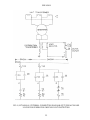
Pickup-voltage Test
The pickup voltage should be checked; for the IAV51D, IAV51K, and IAV52K, the pickup voltage
should be checked on more than one tap. See relay nameplate for value of pickup voltage (closing
volts). Test connections, Fig. 10, are the same as for the time-voltage test except that the timer is not
required.
Time-voltage Test
The time-voltage curves should be checked for one or more settings. Recommended test connections
for this test are shown in Fig. 10.

GEK-45404
13
INSTALLATION
INSPECTION
At the time of installation, the relay should be inspected for tarnished contacts, loose screws, or other
imperfections. If any trouble is found, it should be corrected; see MAINTENANCE. Check the
nameplate for model number and rating.
LOCATION
The location should be clean and dry, free from dust and excessive vibration, and well lighted to
facilitate inspection and testing.
MOUNTING
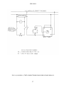
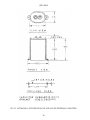
The relay should be mounted on a vertical surface. The outline and panel drilling dimensions are
shown in Fig. 14 for relay Types IAV51D, IAV52D, and IAV52C. Fig. 15 shows outline and panel
drilling for relay Types IAV51K and IAV52K.
CONNECTIONS
Internal connections are shown in Figs. 3 to 7 for the various relays.
GROUND CONNECTIONS
One of the mounting studs or screws should be permanently grounded by a conductor not less than
No. 12 B&S gage copper wire or its equivalent.
OPERATION
Before the relay is put in service, the pickup-voltage and time-voltage tests described under
ACCEPTANCE TESTS (ELECTRICAL TESTS) should be made to determine that factory
adjustments have not been disturbed.
The relay may be tested while mounted on the panel, either from its own or another source of power,
by inserting a separate testing plug in place of the connecting plug. Or, the cradle can be drawn out
and replaced by another that has been laboratory tested.

GEK-45404
14
ADJUSTMENTS
Target and Seal-in Unit
For trip coils operating on current ranging from 0.2 up to 2.0 amperes at the minimum control
voltage, set the target and seal-in tap plug in the 0.2- ampere tap.
For trip coils operating on currents ranging from 2 to 30 amperes at the minimum control voltage,
place the tap plug in the 2.0-ampere tap.
The tap plug is the screw holding the right-hand stationary contact of the seal-in element. To change
the tap setting, first remove the connecting plug. Then, take a screw from the left-hand stationary
contact and place it in the desired tap. Next, remove the screw from the other tap, and place it in the
left-hand contact. This procedure is necessary to prevent the right- hand stationary contact from
getting out of adjustment. Screws should not be in both taps at the same time, as pickup for DC will
be the higher tap value and AC pickup will be increased.
Voltage Setting
The voltage at which the contacts operate may be changed by changing the tap of the IAV51D,
IAV52D, and IAV51K relays.
The pickup of any of the relays, when set for minimum pickup, can be adjusted by means of the
spring adjusting ring. The ring may be turned by inserting a tool in the notches around the edge. By
turning the ring, the operating voltage of the IAV52C relay may be brought into agreement with the
nameplate value, and in the same way the IAV51D, IAV51K, and IAV52K relays may be brought
into agreement with the minimum tap setting.
For taps other than minimum, the slide band on the adjustable resistor associated with the selected
tap, in series with the operating coil, should be moved until the pickup is at tap voltage. This
adjustment should not be made until the spring adjustment for minimum pickup is made, since the
spring adjustment sets the basic torque level of the relay.
Adjustments for pickup between calibrated taps can be made by selecting the tap closest to the
desired voltage and then adjusting the resistor band associated with the tap selected.
The relay is adjusted at the factory to operate from any time-dial position at a minimum voltage that
is 8% of rated voltage. The relays reset at 90% or more of the operating value. Operating voltage for
the IAV51D, IAV52D, IAV51K, and IAV52K relays is the minimum voltage for a given tap setting
at which the contacts just make.

GEK-45404
15
Time Setting
The time of operation of the overvoltage relay is determined primarily by the setting of the time dial.
Further adjustment is obtained by moving the permanent magnet along its supporting shelf; moving
the magnet in toward the back of the relay decreases the time, while moving it out increases the time.
Fig. 11 shows the time-voltage characteristics of the IAV51D, IAV52D, IAV51K and IAV52K for
the four tap settings for the Number 1, 5, and 10 time- dial positions. The time-voltage characteristic
of the 1AV52C, which has no taps, is the same as for the "A" tap in the D & K relays.
To make time settings, set the time dial to the number required (to give the desired characteristic) by
turning it until the number lines up with the notch in the adjacent frame. The time indicated by the
curves is the time required to close the relay contacts when the voltage is suddenly increased from a
value below pickup to the value on the curve (expressed in multiples of tap setting). The time
obtained should be the value on the curve ± 15%.
PERIODIC CHECKS AND ROUTINE MAINTENANCE
In view of the vital role of protective relays in the operation of a power system, it is important that a
periodic test program be followed. It is recognized that the interval between periodic checks will
vary depending upon environment, type of relay and the user's experience with periodic testing. Until
the user has accumulated enough experience to select the test interval best suited to his individual
requirements, it is suggested that the points listed under INSTALLATION PROCEDURE be
checked every six months.
* Revised since last issue
MAINTENANCE
These relays are adjusted at the factory and it is advisable not to disturb the adjustments. If for any
reason, they have been disturbed, the following points should be observed in restoring them.
DISK AND BEARINGS
The lower jewel may be tested for cracks by exploring its surface with the point of a fine needle. If it
is necessary to replace the jewel, the new jewel should be turned up until the disk is centered in the
air gap, after which it should be locked in position by the set screw provided for the purpose.

GEK-45404
16
CONTACT CLEANING
For cleaning fine silver contacts, a flexible burnishing tool should be used. This consists of a
flexible strip of metal with an etched roughened surface, resembling in effect a superfine file. The
polishing action is so delicate that no scratches are left, yet corroded material will be removed
rapidly and thoroughly. The flexibility of the tool ensures the cleaning of the actual points of
contact.
Fine silver contacts should not be cleaned with knives, files, or abrasive paper or cloth. Knives or
files may leave scratches, which increase caring and deterioration of the contacts. Abrasive paper or
cloth may leave minute particles of insulating abrasive material in the contacts and thus prevent
closing.
The burnishing tool described above can be obtained from the factory.
SERVICING
For servicing and adjustments see applicable instructions under ACCEPTANCE TESTS,
INSTALLATION, AND MAINTENANCE.
RENEWAL PARTS
It is recommended that sufficient quantities of renewal parts be carried in stock to enable the prompt
replacement of any that are worn, broken, or damaged. Parts bulletin number GEF-3897 gives a list
of those most subject to wear in ordinary operation, or to damage due to possible abnormal
conditions.
When ordering renewal parts, address the nearest Sales Office of the General Electric Company,
specify quantity required, and give name of part wanted, complete nameplate data, including serial
number. If possible give the General Electric Company's requisition on which the relay was
furnished.

GEK-45404
17
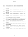
LIST OF FIGURES
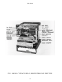
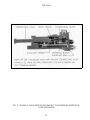
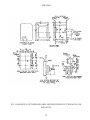
FIG. 1 (8043181) TYPE IAV51D RELAY, REMOVED FROM CASE, FRONT VIEW
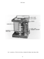
FIG. 2 (8043182) TYPE IAV51D RELAY, REMOVED FROM CASE, REAR VIEW
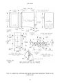
FIG. 3 (K6400439-5) INTERNAL CONNECTIONS OF THE TYPE IAV51D RELAY,
FRONT VIEW
FIG. 4 (0362A514-3) INTERNAL CONNECTIONS OF THE TYPE IAV51K RELAY,
FRONT VIEW
FIG. 5 (K6556505-0) INTERNAL CONNECTIONS OF THE TYPE IAV52C RELAY,
FRONT VIEW
FIG. 6 (0418A790-0) INTERNAL CONNECTIONS OF THE TYPE IAV52D RELAY,
FRONT VIEW
FIG. 7 (0257A8379-0) INTERNAL CONNECTIONS OF THE TYPE IAV52K RELAY,
FRONT VIEW
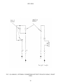
FIG. 8 (0275A2004-0) EXTERNAL CONNECTION DIAGRAM OF TYPES IAV51K AND
IAV52K FOR GENERATOR GROUND-FAULT PROTECTION
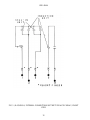
Fig. 9 (0275A2003-0) EXTERNAL CONNECTION DIAGRAM OF TYPE IAV51D AND
IAV52C FOR GROUND-FAULT DETECTION ON AN UNGROUNDED SYSTEM
FIG. 10 (K6154391-3) TEST CONNECTIONS FOR OVERVOLTAGE RELAYS
FIG. 11 (0178A8140-0) TIME VOLTAGE CURVES FOR TYPES IAV51D, 51K, 52D, AND
52K RELAYS
FIG. 12 (8025039) CROSS SECTION OF DRAWOUT CASE SHOWING POSITION OF
AUXILIARY BRUSH
FIG. 13 (0275A4399-0) OUTLINE OF IAV51K AND IAV52K EXTERNAL CAPACITOR
FIG. 14 (K6209270-2) OUTLINE AND PANEL DRILLING FOR RELAY TYPES IAV51D,
52D AND IAV52C
FIG. 15 (K6209271-7) OUTLINE AND PANEL DRILLLING FOR RELAY TYPES IAV51K
AND IAV52K

GEK-45404
18
FIG. 1 (8043181-0) TYPE IAV51D RELAY, REMOVED FROM CASE, FRONT VIEW

GEK-45404
19
FIG. 2 (8043182-0) TYPE IAV51D RELAY, REMOVED FROM CASE, REAR VIEW

GEK-45404
20
FIG. 3 (K-6400439-5) INTERNAL CONNECTIONS OF THE TYPE IAV51D RELAY, FRONT
VIEW
Page is loading ...
Page is loading ...
Page is loading ...
Page is loading ...
Page is loading ...
Page is loading ...
Page is loading ...
Page is loading ...
Page is loading ...
Page is loading ...
Page is loading ...
Page is loading ...
-
 1
1
-
 2
2
-
 3
3
-
 4
4
-
 5
5
-
 6
6
-
 7
7
-
 8
8
-
 9
9
-
 10
10
-
 11
11
-
 12
12
-
 13
13
-
 14
14
-
 15
15
-
 16
16
-
 17
17
-
 18
18
-
 19
19
-
 20
20
-
 21
21
-
 22
22
-
 23
23
-
 24
24
-
 25
25
-
 26
26
-
 27
27
-
 28
28
-
 29
29
-
 30
30
-
 31
31
-
 32
32


GE MULTILIN IAV51D User manual
- Category
- Power generators
- Type
- User manual
Ask a question and I''ll find the answer in the document
Finding information in a document is now easier with AI
Related papers
Other documents
-
Legacy Car Audio LW15590 User manual
-
ABB CV-4 Instruction Leaflet
-
ABB CP Series Instruction Leaflet
-
-
-
Mitsubishi Electric Low-Voltage Air Circuit Breakers series Type AE-SW User manual
-
WEG DWB160 UL Installation guide
-
-
 GE Multilin 345 User manual
-
