Page is loading ...

Save this manual for future reference.
DIRECT-VENT GAS FIREPLACE
OWNER’S OPERATION AND INSTALLATION MANUAL
®
EVDDVF36PN (PENINSULA) AND EVDDVF36STN (SEE THRU)
NATURAL GAS - ELECTRONIC IGNITION
This appliance may be installed in an aftermarket* permanently located, manufactured (mobile) home, where not
prohibited by state or local codes.
This appliance is only for use with the type of gas indicated on the rating plate.
This appliance is not convertible for use with other gases, unless a certified kit is used.
*Aftermarket: Completion of sale, not for purpose of resale, from the manufacturer.
— Do not store or use gasoline or other flammable
vapors and liquids in the vicinity of this or any
other appliance.
— WHAT TO DO IF YOU SMELL GAS :
• Do not try to light any appliance.
• Do not touch any electrical switch;
• Do not use any phone in your building.
• Immediately call your gas supplier from a
neighbor’s phone. Follow the gas supplier’s
instructions.
• If you cannot reach your gas supplier, call the
fire department.
— Installation and service must be performed by a
qualified installer, service agency, or the gas
supplier.
SAVE THIS BOOK
This book is valuable. In addition to instructing
you on how to install and maintain your appli-
ance, it also contains information that will
enable you to obtain replacement parts or
optional accessory items when needed. Keep
it with your other important papers.
WARNING: Improper installation,
adjustment, alteration, service, or
maintenance to this appliance can
cause injury or property damage.
Refer to this manual. For assistance
or additional information consult a
qualified installer, service agency,
or the gas supplier.
CHECK LOCAL CODES PRIOR TO INSTALLATION
WARNING: If the information in these instruc-
tions is not followed exactly, a fire or explosion
may result causing property damage, personal
injury, or loss of life.
WARNING: This Direct-Vent Gas
Fireplace series is intended for use
with Natural or Propane/LP gas only.
Do not attempt to burn any solid
fuels in these appliances.
(Peninsula
Shown)

2
106573
DIRECT-VENT GAS FIREPLACE
EVDDVF36PN and EVDDVF36STN
®
FRONT VIEW
30
(76cm)
(Opening)
23
5
/
8
(60cm)
25 (64cm)
RIGHT SIDE
22
5
/
8
(57cm)
43
1
/
8
(110cm)
32 (81cm) (Opening)
1
7
/
8
(5cm)
1
1
/
4
(3cm)
BACK VIEW
39
3
/
4
(101cm)
26
3
/
8
(67cm)
3 (8cm)
1 (3cm)
2 (5cm)
3 (8cm)
22
5
/
8
(57cm)
34
3
/
4
(88cm)
TOP VIEW
(Left Side)
(Right Side)
(Front)
(Back)
23
5
/
8
(60cm)
11
15
/
16
(30cm)
10
1
/
2
(27cm)
ø1.5
(4cm)
ø1.5
(4cm)
11
1
/
8
(28cm)
FRONT VIEW
30
(76cm)
(Opening)
25 (64cm)
19
7
/
8
(50cm)
(Opening)
RIGHT SIDE
1
1
/
4
(3cm)
22
5
/
8
(57cm)
41
1
/
8
(104cm)
32 (81cm) (Opening) 1
7
/
8
(5cm)
39
3
/
4
(101cm)
26
3
/
8
(67cm)
3 (8cm)
1 (3cm)
2 (5cm)
22
5
/
8
(57cm)
34
3
/
4
(88cm)
3 (8cm)
BACK VIEWTOP VIEW
(Left Side)
(Right Side)
(Front)
(Back)
23
5
/
8
(60cm)
10
1
/
2
(27cm)
ø1.5
(4cm)
ø1.5
(4cm)
10
1
/
2
(27cm)
11
15
/
16
(30cm)
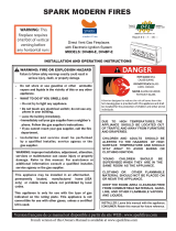
Figure 1 - EVDDVF36PN (Peninsula) Dimensions
Back of
Surround
Back of
Surround
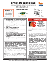
Figure 2 - EVDDVF36STN (See Thru) Dimensions
Left Side
Surround
Right Side
Surround
Rating Plate
Location
Left Side
Surround
Right Side
Surround
GLOSSARY OF
TERMS
Chase - A box-like enclosure to protect
venting from the elements when the venting
run is on the outside of a structure.
Mastic - A pliable sealant for use around
the vent terminal.
Snorkel Termination - A box that raises
the horizontal termination above ground
level clearances.
Vent Terminal - Mounted on an outside
wall or roof to separate the inlet and outlet of
the vent system and protect it from weather.
Vinyl Siding Standoff - A metal box that
separates the vent cap from vinyl siding.
Wall Thimble/Firestop - A metal plate
used to secure the vent pipe when it passes
through a wall or ceiling.
Alternate
Bottom Gas
Supply Inlets
Alternate
Bottom Gas
Supply Inlets
Rating Plate
Location
Note:
All dimensions in this manual are in inches unless otherwise specified.
Top Spacer
Top Spacer

3
106573
OWNER’S MANUAL
Model EVDDVF36PN series is a three-sided
direct-vent gas fireplace with a sealed com-
bustion chamber. Model EVDDVF36STN
series is a two-sided direct-vent gas fire-
place with a sealed combustion chamber.
These models are equipped with an elec-
tronic direct spark ignition system and re-
quire household electricity to operate. A fan
kit is available for these models as an option
(see Accessories on page 26).
INTRODUCTION
WARNING: Installation and
repair should be done by a quali-
fied installer/service person. The
appliance should be inspected
before use, and at least annually
thereafter by a qualified service
person. More frequent cleaning
may be required due to exces-
sive lint from carpeting, bedding,
pet hair, etc. It is imperative that
the control compartments, burn-
ers, and circulating air systems
be kept clean.
NOTICE: This appliance is in-
tended to be used only for supple-
mental heat.
• Models EVDDVF36PN and
EVDDVF36STN use NATURAL GAS
ONLY.
If you have any doubts as to which gas your
particular appliance is approved and tested
for, please check the AGA/CGA rating plate
located at the interior of the appliance open-
ing or consult your local distributor (see
Figures 1 and 2, page 2).
BEFORE YOU BEGIN
Before beginning the installation of your
appliance, read these instructions through
completely.
This DESA appliance and its approved com-
ponents are safe when installed according to
this installation manual and operated as
recommended by DESA. Unless you use
DESA approved components tested for this
appliance, YOU MAY CAUSE A SAFETY
HAZARD!
The DESA warranty will be voided by, and
DESA disclaims any responsibility for the
following actions:
A) Modification of the appliance or any of
the components manufactured by
DESA unless otherwise permitted in
writing by DESA.
B) The use of any components part not ap-
proved by DESA in combination with
this DESA appliance.
C) Installation and/or operation in a man-
ner other than instructed in this manual.
D) The burning of anything other than the
type of gas approved for use in this gas
appliance.
NOTICE: Check local building
codes for area requirements be-
fore installing this appliance.
This appliance, when installed, must be elec-
trically grounded in accordance with local
codes, or in the absence of local codes, with the
National Electrical Code, ANS/NFPA 70 or
the Canadian Electrical Code, CSA C22.1.
The installation must conform with local codes
or, in the absence of local codes, with the
National Fuel Gas Code, ANS Z223.1 or the
Canadian Installation Code, CAN/CGA B149.
This appliance complies with ANS Z21.50-
1998/CSA 2.22-M48 as a VENTED GAS
FIREPLACE. It is listed and tested by Inter-
national Approval Services.
To determine the safest and most efficient
location for your appliance, consider the
following guidelines:
1. The location must allow for proper
clearances (see Clearances, page 4).
2. Consider a location where heat output
would not be affected by drafts, air con-
ditioning ducts, windows, or doors.
3. A location that avoids the cutting of
joists or roof rafters makes installation
easier.
SELECTING
LOCATION
In selecting a location, the following pre-
cautions must be observed:
1. A projection may be ideal for a new ad-
dition on an existing finished wall. See
Horizontal Termination Configuration,
pages 10 and 11, or Vertical Termina-
tion Configuration, pages 13 and 14.
2. Do not locate appliance close to where
gasoline or other flammable liquids
may be stored. The appliance must be
kept clear and free from combustible
materials.
3. Do not connect this appliance to a
chimney system used for solid fuel
burning fireplace.
4. Due to high temperatures, do not lo-
cate this appliance in high traffic areas
or near furniture and draperies.
5. This fireplace may be installed in bed-
rooms or bathrooms in accordance with
local codes.
6. Never obstruct the openings of the ap-
pliance or flow of ventilation air. Keep
the control compartments accessible.
7. Do not use this appliance if any part
has been under water. Immediately con-
tact a local service technician to exam-
ine the appliance and to replace any
part(s) of the control ignition system
and other related components that have
submerged under water.
Figure 3 - Possible Installation of
Peninsula Fireplace

4
106573
DIRECT-VENT GAS FIREPLACE
EVDDVF36PN and EVDDVF36STN
®
FRAMING
Once the final location has been determined,
observing height clearances for vent termi-
nation, you may construct framing using
dimensions shown in Figures 7 through 9,
page 5, depending on your installation.
If the appliance is to be installed directly on
carpeting, tile (other than ceramic), or any
combustible material other than wood floor-
ing, the appliance must be installed on a
metal or wood panel extending the full width
and depth of the appliance. There are three
holes on each side of the bottom of the unit
where screws can be used to secure the unit
to the floor.
CLEARANCES
Minimum clearances to combustibles are:
• Back and Sides
of Surround: .............................0" min.
• Vent Surfaces:
Vertical Runs:................ 1" (5cm) min.
Top of Horizontal Runs . 2" (5cm) min.
• Ceiling to Opening:... 36" (91cm) min.
• Floor:........................................0" min.
• Wall to Front of Glass:36" (91cm) min.
• Perpendicular Wall to
Opening of Unit: ........... 2" (5cm) min.
• Top Spacer: ..............................0" min.
Figure 4 - Minimum Clearances (Peninsula Shown)
Figure 5 - Minimum Clearances (See Thru Shown)
CAUTION: Do not block re-
quired air spaces with insula-
tion or any other material. Do not
obstruct the effective opening of
the appliance with any type of
facing material.
MANTEL CLEARANCES
Woodwork, such as wood trims, mantels,
and other combustible materials projecting
no more than 1
1
/2 inches (3.8cm) shall not
be placed within 7 inches (17.8cm) from the
opening of the unit. Combustible material
above and projecting more than 1
1
/2 inches
(3.8cm) from the appliance’s face must not
be placed less than 15 inches (38.1cm) from
the louver opening (see Figure 6).
Figure 6 - Mantel Clearances for Peninsula
and See Thru Fireplaces (Peninsula
Shown)
PRE-INSTALLATION
PREPARATION
CEILING
WALL
36"
(914mm)
Min.
36"
(914mm)
Min.
0" Floor
12"
(305mm)
Min.
21"
(533mm)
Min.
15"
(381mm)
Min.
4"
(102mm)
Min.
7" (178mm)
Min.
1
1
/
2
" (38mm)
Min.
UNIT
Spacer
2 x 4
Combustible
Material May
Be Used
Drywall (Gypsum
Board, Sheetrock, Etc.)
Safe Zone for
Projection of
Combustible
Material
0"
36"
(914mm)
2" (51mm)
Wall In Front Of Glass
36" (91cm) Min.
Perpendicular
Wall 2" (51mm)
Min. From Opening
Right Side
Surround
(0" Min.)
Left Side
Surround
(0" Min.)
TOP VIEW
*Combustible
Material
Drywall
2 x 4 Stud
Minimum 1"
Clearance from Side
(Only for See Thru)
Top of Louver
Opening
Top Spacer
* May be attached with screws to the surround.

5
106573
OWNER’S MANUAL
Figure 7 - Rough Opening for Installing
Peninsula Fireplace
39
3
/
4
"
(1010mm)
Min.
40
1
/
2
"
(1029mm)
23
5
/
8
"
(600mm)
39
3
/
4
"
(1010mm)
Min.
40
1
/
2
"
(1029mm)
23
5
/
8
"
(600mm)
*
Figure 8 - Rough Opening for Installing
Peninsula Fireplace on Platform
* As required by design as long as ceiling
clearance is maintained.
Platform Must Be
Solid, Flat, and
Fully Supported
39
3
/4"
(1010mm)
Min.
43
1
/4"
(1098mm)
23
5
/
8
"
(600mm)
Figure 9 - Rough Opening for Installing
See Thru Fireplace
3" (76mm)
1" (25mm)
Dia. Hole
3"
(76mm)
2" (51mm)
Dia. Hole
1"
(25mm)
2"
(51mm)
Height
Depends On
Installation
10"
(254mm)
Square Min.
Figure 10 - Hole Locations For Gas Line
and Electric Wires for Peninsula and See
Thru Fireplaces
Figure 11 - Rough Opening for Installing
Exterior Vent Terminal
These models are approved for use with
Simpson Dura-Vent 6
5
/8" direct-vent pipe
components and terminations as well as both
flex and rigid Vanguard vent components.
Your fireplace is approved to be vented either
through the side wall, or vertically using the
following guidelines:
• Only use Vanguard or Simpson Dura-
Vent GS venting components or kits spe-
cifically approved for this fireplace.
• Minimum clearance between vent pipes
and combustible materials is 1" (25 mm),
except where stated otherwise.
• Combustible material may be flush with
the top front of fireplace with a maxi-
mum thickness of 3/4".
• Do not recess venting terminals into a
wall or siding.
• If installing on vinyl siding a vinyl sid-
ing standoff must be used (see Figure 19,
page 9).
• Install horizontal venting with a 1/4"
rise for every 12" of run toward the ter-
mination.
• You may paint the vent terminal with
450°F (232°C) heat-resistant paint to co-
ordinate with the exterior finish.
• There must not be any obstruction such
as bushes, garden sheds, fences, decks,
or utility buildings within 24" from the
front of the termination cap.
• Do not locate termination cap where ex-
cessive snow or ice build up may occur.
Be sure to clear vent termination area af-
ter snow falls to prevent accidental block-
age of venting system. When using snow
blowers, do not direct snow towards vent
termination area.
LOCATION OF VENT
TERMINATION
When locating vent termination, it is impor-
tant to observe the minimum clearances
shown in Figure 13, page 6. You will avoid
extra framing by positioning your fireplace
against an already existing framing mem-
ber. The sides of the fireplace may be posi-
tioned directly against combustible walls.
*Check with local codes or with the current
CAN/CGA B149[.1 or .2] Installation Codes
for Canada or the USA Installations follow
the current National Fuel Gas Code, ANS
Z223.1, also known as NFPA 54.
GENERAL VENTING
Vertical Height
Depends on
Installation
26
3
/8"
(670mm)
Horizontal
Length Depends
on Installation
90
o
Elbow
45
o
Elbow
PRE-INSTALLATION
PREPARATION
Continued
Refer to Pages
8 through 14
for Horizontal
and Vertical
Installation
Details
Figure 12 - Vent Opening Height
Continued

6
106573
DIRECT-VENT GAS FIREPLACE
EVDDVF36PN and EVDDVF36STN
®
Fixed
Closed
Openable
Fixed
Closed
Openable
V
V
V
V
V
V
V
V
X
X
V
X
G
G
J
F
B
B
K
N
H
I
A
N
E
L
D
B
M
A
C
B
V
V
A
G
G
B
TERMINATION CAP
AIR SUPPLY INLET
GAS METER RESTRICTED AREA
(TERMINATION PROHIBITED)
A = clearance above grade, veranda, porch, deck, or balcony
[*12 inches (305mm) minimum]
B = clearance to window or door that may be opened
[12 inches (305mm) minimum]
C = clearance to permanently closed window [minimum 12 inches
(305mm) recommended to prevent condensation on window]
D = vertical clearance to ventilated soffit located above the terminal
within a horizontal distance of 24 inches (610mm) from the
center-line of the terminal [18 inches (457mm) minimum]
E = clearance to unventilated soffit [12 inches (305mm) minimum]
F = clearance to outside corner (see below)
G = clearance to inside corner (see below)
H = *not to be installed above a meter/regulator assembly within
36 inches (914mm) horizontally from the center-line of the regulator
I = clearance to service regulator vent outlet [*72 inches (1829mm)
minimum]
J = clearance to non-mechanical air supply inlet to building or the
combustion air inlet to any other fireplace [*12 inches (305mm)
minimum]
K = clearance to a mechanical air supply inlet [*72 inches (1829mm)
minimum]
L = † clearance above paved side-walk or a paved driveway located on
public property [*84 inches (2133mm) minimum]
M = clearance under veranda, porch, deck [*12 inches (305mm) minimum ‡]
N = clearance above a roof shall extend a minimum of 24 inches (610mm)
above the highest point when it passes through the roof surface and
any other obstruction within a horizontal distance of 18 inches (457mm)
† vent shall not terminate directly above a side-walk or paved driveway which is located between two
single family dwellings and serves both dwellings*
‡ only permitted if veranda, porch, deck or balconey is fully open on a minimum of 2 sides beneath the floor*
* as specified in CAN/SGA B149 (.1 or .2) Installation Codes (1991) for Canada or for U.S.A. installation follow
the current
National Fuel Gas Code, ANS Z223.1
Note: Local codes or regulations may require different clearances
A = 6" (152mm)
Inside Corner
V
B
E
V
B = 6" (152mm)
C = Maximum depth of 48" (1219mm) for
recessed location
D = Minimum width for back wall of
recessed location -
Combustible - 38" (965mm)
Noncombustible - 24" (610mm)
E = Clearance from corner in
recessed location-
Combustible - 6" (152mm)
Noncombustible - 2" (51mm)
Outside Corner Recessed Location
G
H
G = Combustible 24" (610mm)
Noncombustible 18" (457mm)
Balcony with No Side Wall
V
J
Combustible &
Noncombustible
H = 24" (610mm)
J = 20" (508mm)
Balcony with Perpendicular Side Wall
C
D
C
Termination Clearances for Buildings with Combustible and Noncombustible Exteriors
Figure 13 - Minimum Clearances for Vent Terminations
GENERAL VENTING
Continued

7
106573
OWNER’S MANUAL
WARNING: Read all instruc-
tions completely and thoroughly
before attempting installation.
Failure to do so could result in
serious injury, property damage
or loss of life. Operation of im-
properly installed and maintained
venting system could result in
serious injury, property damage
or loss of life.
WARNING: Seal all of the outer
pipe connections with high tem-
perature silicone (600°F/316° C)
every time a vent connection is
made. Before joining elbows and
pipes, apply a small bead of high
temperature silicone sealant (GE
RTV 106/Loctite RTV 81585) to
the outer section of male end of
the elbow or pipe. High tempera-
ture silicone must also be used
to re-seal any connections after
maintenance to venting system.
NOTICE: Failure to follow these
instructions will void the warranty.
INSTALLATION
PRECAUTIONS
Consult local building codes before begin-
ning the installation. The installer must make
sure to select the proper vent system for
installation. Before installing vent kit, the
installer must read this fireplace manual and
vent kit instructions.
Only a qualified installer or service person
should install venting system. The installer
must follow these safety rules:
• Wear gloves and safety glasses for
protection
• Use extreme caution when using ladders
or when on roof tops
• Be aware of electrical wiring locations
in walls and ceilings
The following actions will void the war-
ranty on your venting system:
• Installation of any damaged venting
component
• Unauthorized modification of the vent-
ing system
VENTING
INSTALLATION
WARNING: This gas fireplace
and vent assembly must be
vented directly to the outside.
The venting system must NEVER
be attached to a chimney serving
a separate solid fuel burning ap-
pliance. Each gas appliance must
use a separate vent system. Do
not use common vent systems.
WARNING: Horizontal sec-
tions of this vent system require
a minimum clearance of 2" from
the top of the vent pipe and 1"
minimum to the sides and bot-
tom. Vertical sections of this sys-
tem require a minimum of 1" clear-
ance to combustible materials on
all sides of the vent pipe.
• Installation of any component part not
manufactured or approved by DESA
International
• Installation other than as instructed by
these instructions
INSTALLATION PLANNING
There are two basic types of direct-vent
installation:
• Horizontal Termination
• Vertical Termination
It is important to select the proper length of
vent pipe for the type of termination you
choose. It is also important to note the wall
thickness.
For Horizontal Termination: Select the
amount of vertical rise desired. The horizon-
tal run of venting must have 1/4" rise for
every 12" of run towards the termination.
NOTICE: Treatment of firestops
and construction of the chase may
vary from building type to build-
ing type. These instructions are
not substitutes for the require-
ments of local building codes. You
must follow all local building
codes.
Note:
When installing in a chase, you should
insulate the chase as you would the outside
walls of your home. This is especially im-
portant in cold climates. Minimum clear-
ance between vent pipes and combustible
materials such as insulation is 1".
After framing the chase (see Framing on
pages 4 and 5) install the vent system by
following the installation instructions.
Installing Vent System in a Chase
A chase is a vertical box-like structure built
to enclose venting that runs along the out-
side of a building. A chase is not required for
such venting.
Continued
WARNING: Never run the vent
downward as this may cause ex-
cessive temperatures which
could cause a fire.
You may use one or two 90° elbows in this
vent configuration. See Horizontal Termina-
tion Configurations on pages 10 and 11.
For Vertical Termination: Measure the
distance from the fireplace flue outlet to the
ceiling. Add the ceiling thickness, the verti-
cal rise in an attic or second story, and allow
for sufficient vent height above the roofline.
You may use one or two 90° elbows in this
vent configuration. See Vertical Termination
Configurations on pages 13 and 14.
Note:
You may use two 45° elbows in place
of a 90° elbow. You must follow rise to run
ratios when using 45° elbows.
For two-story applications, firestops are re-
quired at each floor level. If an offset is
needed in the attic, additional pipe and el-
bows will be required.
You may use a chase with a vent termination
with exposed pipe on the exterior of the
house. See Installing Vent System in a Chase,
below.
Your Vanguard direct-vent fireplace has
been tested for a minimum 3' rise with a
maximum 10" wall thickness. The maxi-
mum horizontal run is 20' with 8' vertical
rise (see Installation for Horizontal Termi-
nation, page 8). The maximum vertical run
is 30' (see Installation for Vertical Termina-
tion, page 12).
It is very important that the venting system
maintain its balance between the combus-
tion air intake and the flue gas exhaust.
Certain limitations apply to vent configura-
tions and must be strictly followed.

8
106573
DIRECT-VENT GAS FIREPLACE
EVDDVF36PN and EVDDVF36STN
®
INSTALLATION FOR
HORIZONTAL TERMINATION
1. Determine the route your horizontal
venting will take.
Note:
The location
of the horizontal vent termination on
the exterior wall must meet all local and
national building codes and must not
be easily blocked or obstructed.
Snorkel terminations are available for
terminations requiring a vertical rise on
the exterior of the building (see Figures
14 and 15). Snorkel kit SVK is also
available (see page 15). Follow the same
installation procedures used for standard
horizontal terminations. If installing the
snorkel termination below grade (base-
ment applications), you must provide
proper drainage to prevent water from
entering the snorkel termination (see
Figure 15). Do not back fill around the
snorkel termination.
2. Rigid vent pipes and fittings have spe-
cial twist-lock connections. Assemble
the desired combination of pipe and el-
bows to the appliance adaptor with pipe
seams oriented towards the wall or floor.
Twist-lock Procedure: The female
ends of the pipes and fittings have four
locking lugs (indentations). These lugs
will slide straight into matching slots on
the male ends of adjacent pipes and fit-
tings. (All connections must be sealed
with high temperature silicone sealant
as specified in the second warning state-
ment on page 7.) Push the pipe sections
together and twist one section clockwise
approximately one-quarter turn until the
sections are fully locked. See Figure 16,
page 9.
Note:
Horizontal runs of vent
must be supported every three feet. Use
wall straps for this purpose.
Flexible vent pipe must be installed with
spacer springs every 12". See Figure 16,
page 9. All connections must be clamped
tightly and sealed with high temperature
silicone sealant as specified in the sec-
ond warning statement on page 7.
VENTING
INSTALLATION
Continued
Figure 15 - Snorkel Termination with Drainage Pipe
Adequate
Drainage
12" Minimum
Figure 14 - Snorkel Termination
Snorkel
12" Minimum
WARNING: Do not recess vent
terminal into a wall or siding.
Snorkel
1' Minimum
90°
45°
1' Minimum
90°
45°

9
106573
OWNER’S MANUAL
UP
UP
VENTING
INSTALLATION
Continued
(Framing
Detail)
10"
(254mm)
10"
(254mm)
7 1/2"
(190mm)
Vent Opening
Combustible Wall
Vent Opening
Non-Combustible Wall
Figure 17 - Vent Opening Requirements
Continued
3. Attach vent pipe assembly to the fire-
place. Set fireplace in front of it’s per-
manent location to insure minimum
clearances. Mark the wall for a 10"
square hole (for noncombustible ma-
terial such as masonry block or con-
crete, a 7
1
/2" diameter hole is accept-
able). See Figure 17. The center of the
hole should line up with the center-
line of the horizontal rigid vent pipe.
Cut a 10"x10" (254mm x 254mm)
square hole through combustible ex-
terior wall (7
1
/2" [190mm] diameter
hole if noncombustible). Frame as nec-
essary (see Figure 17).
Figure 19 - Installing Vinyl Siding Standoff
Cut Vinyl Siding
Away to Fit
Standoff
Wood Screw
Nut
Bolt
Standoff
Vent Cap
Figure 16 - Vent Pipe Connections
Female
Locking
Lugs
Male
Slots
Rigid Vent Pipe Flexible Vent Pipe
Spacer
Spring
4" Clamp
7" Clamp
4" Flex
Pipe
7" Flex
Pipe
Apply Mastic
to All Four Sides
Figure 18 - Installing Horizontal Vent Cap
Wood
Screw
Vent Cap
Apply Mastic
to All Four
Sides
WARNING: Do not recess vent
termination in to any wall. This
will cause a fire hazard.
4. Apply a bead of non-hardening mastic
around the outside edge of the vent cap.
Position the vent cap in the center of
the 7
1
/2" or 10" hole on the exterior
wall with the arrow on the vent cap
pointing up. Insure proper clearance of
1" to combustibles is maintained. At-
tach the vent cap with four wood screws
supplied (see Figure 18).
Note
: Re-
place the wood screws with appropri-
ate fasteners for stucco, brick, concrete,
or other types of siding.
For vinyl siding use vinyl siding stand-
offs between vent cap and exterior wall.
The vinyl siding standoff prevents ex-
cessive heat from melting the vinyl sid-
ing material. Bolt the vent cap to the
standoff. Apply non-hardening mastic
around outside edge of the standoff in-
stead of the vent cap assembly. Use
wood screws provided to attach the
standoff. See Figure 19.
5. Slide the wall thimble over the vent pipe
before connecting the horizontal run to
the vent cap (see Figure 20).
6. Carefully move the fireplace with vent
assembly attached toward the wall and
insert the vent pipe into the horizontal
termination. The pipe overlap should be
a minimum of 1
1
/4". Apply silicone to
the connection. Fasten all vent connec-
tions with screws provided. Refer to
Framing on pages 4 and 5 for instruc-
tions on securing unit to framing or floor.
7. Slide the wall thimble against the inte-
rior wall surface and attach with screws
provided (see Figure 20).
Vent Cap
(Horizontal
Termination)
Interior Wall
Surface
Wall
Thimble
Horizontal
Vent Pipe
Figure 20 - Connecting Vent Cap with
Horizontal Vent Pipe
Screw
Vinyl Siding Standoff

10
106573
DIRECT-VENT GAS FIREPLACE
EVDDVF36PN and EVDDVF36STN
®
VENTING
INSTALLATION
Continued
UP
Figure 21 - Horizontal Termination Configuration for Rigid Venting Using One
90° Elbow
Figure 22 - Horizontal Termination Using Flexible Venting
Horizontal Venting
Vertical (V) Horizontal (H)
49.5" min. 15" max.
(45° elbow, 1' vertical pipe, 90° elbow)
61.5" min. 34" max.
73.5" min. 58" max.
85.5" min. 10' max.
102.5" min. 20' max.
UP
Horizontal Venting
See information in
Figure 21 for
Vertical(V) and
Horizontal(H) maxi-
mums and minimums.
The same amounts
apply for flexible
venting.
FGFVK Vent Kit Shown
Horizontal Termination
Configurations
Figures 21 through 23 show different con-
figurations for venting with horizontal ter-
mination. Each figure includes a chart with
vertical minimum/maximum and horizon-
tal maximum dimensions which must be
met. All connections must be sealed with
high temperature silicone sealant as speci-
fied in the second warning statement on
page 7. All horizontal terminations require
1/4" rise per 12" of horizontal run.
Note:
The 30° Starter
Elbow Must Be
Discarded and
Replaced with a 45°
Starter Elbow.
45° Starter
Elbow
Required

11
106573
OWNER’S MANUAL
VENTING
INSTALLATION
Continued
Venting with Two 90° Elbows
Vertical (V) Horizontal (H
1
) +
Horizontal (H
2
)
5' min. 4' max.
6' min. 8' max.
7' min. 10' max.
8' min. 15' max.
20' max. 20' max.
Figure 23 - Horizontal Termination Configuration for Rigid Venting Using Two 90° Elbows with Termination at 90° with Fireplace
Continued
45° Starter
Elbow
Required

12
106573
DIRECT-VENT GAS FIREPLACE
EVDDVF36PN and EVDDVF36STN
®
4. Connect a section of pipe and extend
up through the hole.
Note:
If an offset is needed to avoid
obstructions, you must support the vent
pipe every 3 feet. Use wall straps for
this purpose (see Figure 24). Whenever
possible, use 45° elbows instead of 90°
elbows. The 45° elbow offers less re-
striction to the flow of the flue gases
and intake air.
5. Place the flashing over the pipe
section(s) extending through the roof.
Secure the base of the flashing to the
roof and framing with roofing nails. Be
sure roofing material overlaps the top
edge of the flashing as shown in Figure
24. There must be a 1" clearance from
the vent pipe to combustible materials.
6. Continue to add pipe sections until the
height of the vent cap meets the mini-
mum building code requirements de-
scribed in Figure 13 on page 6.
Note
:
You must increase vent height for steep
roof pitches. Nearby trees, adjoining
rooflines, steep pitched roofs, and other
similar factors may cause poor draft or
down-drafting in high winds. Increasing
the vent height may solve this problem.
7. Twist-lock the vent cap onto the last
section of vent pipe and seal with high
temperature silicone sealant as speci-
fied in the second warning statement
on page 7.
Note:
If the vent pipe passes through any
occupied areas above the first floor, including
storage spaces and closets, you must enclose
pipe. You may frame and sheetrock the enclo-
sure with standard construction material. Make
sure and meet the minimum allowable clear-
ances to combustibles. Do not fill any of the
required air spaces with insulation.
Cathedral Ceiling Installation
1. Remove shingles or other roof cover-
ing as necessary to cut the rectangular
hole for the support box. Mark the out-
line of the cathedral ceiling support box
on the roof sheathing using the locat-
ing hole as a center point.
2. Cut the hole 1/8" larger than the sup-
port box outline (see Figure 26, page 13).
1. Determine the route your vertical vent-
ing will take. If ceiling joists, roof
rafters, or other framing will obstruct
the venting system, consider an offset
(see Figure 24) to avoid cutting
loadbearing members.
Note:
Pay spe-
cial attention to these installation in-
structions for required clearances (air
space) to combustibles when passing
through ceilings, walls, roofs, enclo-
sures, attic rafters, etc. Do not pack air
spaces with insulation. Also note maxi-
mum vertical rise of the venting sys-
tem and any maximum horizontal off-
set limitations. Offsets must fall within
the parameters shown in Figure 13 on
page 6.
2. Set the fireplace in desired location.
Drop a plumb line down from the ceil-
ing to the position of the fireplace exit
flue. Mark the center point where the
vent will penetrate the ceiling. Drill a
small locating hole at this point.
Drop a plumb line from the inside of
the roof to the locating hole in the ceil-
ing. Mark the center point where the
vent will penetrate the roof. Drill a
small locating hole at this point.
Flat Ceiling Installation
1. Cut a 10" square hole in the ceiling us-
ing the locating hole as a center point.
The opening should be framed to
10"x10" (254mm x 254mm) inside di-
mensions, as shown in Figure 17 on
page 9 using framing lumber the same
size as the ceiling joists. If the area
above the ceiling is an insulated ceil-
ing or a room, nail firestop from the
top side. This prevents loose insulation
from falling into the required clearance
space. Otherwise, install firestop below
the framed hole. The firestop should be
installed with no less than three nails
per side (see Figure 25).
2. Assemble the desired lengths of pipe
and elbows necessary to reach from the
fireplace flue up through the firestop.
All connections must be sealed with
high temperature silicone sealant as
specified in the second warning state-
ment on page 7. Be sure all pipe and
elbow connections are fully twist-
locked (see Figure 16, page 9).
3. Cut a hole in the roof using the locating
hole as a center point. (Cover any ex-
posed open vent pipes before cutting
hole in roof.) The 10"x10" hole must
be measured on the horizontal; actual
length may be larger depending on the
pitch of the roof. There must be a 1"
clearance from the vent pipe to combus-
tible materials. Frame the opening as
shown in Figure 17 on page 9.
VENTING
INSTALLATION
Continued
Figure 24 - Offset with Wall Strap and 45°
45° Elbow
Wall Strap
Roof
Flashing
Ceiling Firestop
Figure 25 - Installing Firestop
If area above is not a room, install
firestop below framed hole.
If area above is a room, install firestop
above framed hole.
INSTALLATION FOR
VERTICAL TERMINATION
NOTICE: Use rigid pipe only. Flex
venting is not to be used with a
vertical termination.

13
106573
OWNER’S MANUAL
VENTING
INSTALLATION
Continued
Continued
Figure 26 - Cathedral Ceiling Support
Box Installation
Non-hardening Mastic under all
edges of support box before nailing
Figure 27 - Installed Cathedral Ceiling
Support Box
Vertical Termination Configurations
Figures 28 through 31 show four different configurations for vertical termination. All
connections must be sealed with high temperature silicone sealant as specified in the second
warning statement on page 7.
Venting with Two 90° Elbows
Vertical (V) Horizontal (H
1
) +
Horizontal (H
2
)
5' min. 2' max.
6' min. 4' max.
7' min. 6' max.
8' min. 8' max.
20' max. 8' max.
Figure 28 - Vertical Rigid Venting Configuration Using Two 90° Elbows with Two
Horizontal Runs
3. Lower the support box through the hole
in the roof until the bottom of the box
extends at least 2" below the ceiling
(see Figure 26). Align the support box
vertically and horizontally using a level.
Temporarily tack the support box in
place through the inside walls and into
the roof sheathing.
4. Using tin snips, cut the support box from
the top corners down to the roofline and
fold the resulting flaps over the roof
sheathing (see Figure 27). Apply a bead
of non-hardening mastic around the top
edges of the support box to make a seal
between the box and the roof. Nail in
place with roofing nails. Remove any
combustible material that might be in-
side of the support box.
5. Complete the cathedral ceiling instal-
lation by following the same proce-
dures outlined in steps 2 through 7 for
Flat Ceiling Installation, page 12
.
Venting with One 90° Elbow
Vertical (V) Horizontal (H)
5' min. 2' max.
6' min. 4' max.
7' min. 6' max.
8' min. 8' max.
20' max. 8' max.
Figure 29 - Vertical Rigid Venting Configuration Using One 90° Elbow
Cut hole 1/8" larger than support
box when projected onto roofline
2" minimum below
finished ceiling
Cathedral ceiling
support box
Level
45° Starter Elbow
Required
45° Starter Elbow
Required

14
106573
DIRECT-VENT GAS FIREPLACE
EVDDVF36PN and EVDDVF36STN
®
Vertical Venting
V = 40' max.
Figure 31 - Vertical Rigid Venting
Configuration With No Horizontal Run
VENTING
INSTALLATION
Continued
Venting with Two 90° Elbows
Vertical (V
1
) Horizontal (H)
5' min. 6' max.
6' min. 12' max.
7' min. 18' max.
8' min. 20' max.
Note:
Vertical (V
1
) +
Vertical (V
2
) = 20' max.
Figure 30 - Vertical Rigid Venting Configuration Using Two 90° Elbows
RVF Kit Shown
45° Starter
Elbow
Required
45° Starter Elbow
Required

15
106573
OWNER’S MANUAL
VENTING
INSTALLATION
Continued
HIGH ALTITUDE
INSTALLATION
Your Vanguard direct-vent fireplace has
been AGA tested and approved for eleva-
tions from 0-2000 feet and CGA certified
for elevations from 0-4500 feet.
When installing this fireplace at an elevation
above 2000 feet (in the USA), you may need
to decrease the input rating by changing the
existing burner orifice to a smaller size. Re-
duce input 4% for each 1000 feet above sea
level. Check with your local gas company for
proper orifice size identification.
When installing this fireplace at an eleva-
tion above 4500 feet (in Canada), check
with local authorities.
Consult your local gas company to help de-
termine the proper orifice for your location.
For assistance with any high altitude instal-
lation contact DESA International’s Tech-
nical Service Department at 1-800-DESA-
LOG (1-800-337-2564).
PARTS LISTS FOR VENTING
KITS AND COMPONENTS
Vanguard Rigid Venting
Number Description
*CVK Corner Vent Kit
Includes: 7" x 30º Elbow, 7" x 90º
Elbow, 7" Adjustable Galvanized
Pipe (7-12"), 6" Pipe, Wall
Thimble, Horizontal Termina-
tion, RTV Silicone and 20 Screws
*BVK Basement Rigid Vent Kit
Includes: 7" x 30° Elbow, 7" x 4'
Galvanized Pipe, 7" x 90° El-
bow, 7" Adjustable Galvanized
Pipe (7-12"), Wall Thimble,
Horizontal Termination, RTV
Silicone and 20 Screws
Number Description
*SVK Snorkel Rigid Vent Kit
Includes: 7" x 30° Elbow, 7" x 4'
Galvanized Pipe, 7" x 90° El-
bow, 7" Adjustable Galvanized
Pipe (7-12"), Wall Thimble, 36"
Snorkel Termination, RTV Sili-
cone and 28 Screws
*RVF Roof Rigid Vent Kit
Includes: Flue Restrictor, Storm
Collar, 7" x 30° Elbow, 7" x 4'
Galvanized Pipe, 7" x 2' Galva-
nized Pipe, 7" Adjustable Gal-
vanized Pipe (7-12"), Firestop
Support, Roof Flashing, RTV
Silicone, Vertical Termination,
and 26 screws
D1000 7" x 12" Galvanized Coaxial
Pipe (6 pcs.)
D1010 7" x 24" Galvanized Coaxial
Pipe (6 pcs.)
D1020 7" x 48" Galvanized Coaxial
Pipe (6 pcs.)
D1030 7" Adjustable (7-12")
Galvanized Coaxial Pipe
(6 pcs.)
D1050 7" x 6" Galvanized Coaxial
Pipe (6 pcs.)
D2000 7" x 90° Elbow (6 pcs.)
D2010 7" x 45° Elbow (6 pcs.)
D2060 7" x 45° Starter Elbow
D3000 Wall Strap/Offset Support
(6 pcs.)
D3010 Storm Collar (6 pcs.)
D3020 Wall Thimble (6 pcs.)
D3050 Vertical Restrictor (6 pcs.)
D3060 Ceiling Firestop/Support
(6 pcs.)
D3070 Rectangular Horizontal Rigid
Vent Termination Cap
D3071 Adjustable Horizontal Rigid
Vent Termination Cap
D3090 Cathedral Ceiling Support
Box
D4000 Roof Flashing 6/12-9/12
D4010 Roof Flashing 9/12-12/12
D4020 Flex Connector (6 pcs.)
D4030 Flex Wall Thimble (6 pcs.)
D4040 4" Hose Clamp (6 pcs.)
D4050 7" Hose Clamp (6 pcs.)
D5000 Vinyl Siding Standoff (6 pcs.)
SIMPSON DURA-VENT
GS 4" x 6
5
/8 "
Number Description
902 7" x 48" Pipe
903 7" x 36" Pipe
904 7" x 24" Pipe
906 7" x 12" Pipe
907 7" x 9" Pipe
908 7" x 6" Pipe
911 7" Adjustable (11"-14
5
/8") Pipe
940 Wall Thimble
941 Cathedral Ceiling Support Box
943 Roof Flashing 0/12-6/12
943S Roof Flashing 7/12-12/12
945 7" x 45° Elbow
950 Vinyl Siding Standoff
953 Storm Collar
963 Ceiling Firestop
981 36" Snorkel Termination
984 Horizontal Termination Vent Cap
988 Wall Strap
990 7" x 90° Elbow
991 Vertical High Wind Termination
Vanguard Flexible Venting
Number Description
FGFVK Flex Ground Floor Vent Kit
Includes: Flex Adapter, 7" x 4'
Flexible Pipe, 4" x 4' Flexible
Pipe, Wall Thimble, Horizontal
Termination, (4) Spacer Springs,
(2) 4" Hose Clamps, (2) 7" Hose
Clamps, RTV Silicone, and
10 Screws
D1040 7" x 25' Coaxial Flex Pipe
with Spacer Springs
D3080 Rectangular Horizontal
Flex Termination Cap
Vanguard Rigid Venting
(Cont.)
*NOTICE: The 7" x 30° Elbow sup-
plied with kits CVK, BVK, SVK,
and RVF cannot be used. It MUST
be replaced with a 7" x 45º Starter
Elbow (D2060).

16
106573
DIRECT-VENT GAS FIREPLACE
EVDDVF36PN and EVDDVF36STN
®
INSTALLATION
INSTALLING OPTIONAL
WALL MOUNT SWITCH
GWMS2
NOTICE: The GWMS2 includes
25' of wire for installation. Your
fireplace includes 15' of wire for
accessory installation. Choose the
length that best fits your needs
when installing this accessory.
The installation of a wall switch allows you
to activate the gas control valve and turn
the fireplace on and off. The wall switch is
to be connected to the incoming 120 volt
regular household wiring that supplies elec-
tricity to the fireplace. Refer to wiring
diagram on page 22.
For Optional
Fan Kit
From Blower
Assembly
CAUTION: Due to high tem-
peratures, make sure no wires
are touching the bottom of the
firebox.
OPTIONAL BLOWER
ASSEMBLY INSTALLATION
Before blower assembly can be operated, it
must be properly connected to a standard
120 VAC power source. Refer to Wiring
Diagram on page 22.
1. To remove lower louver, pull both top
spring latches toward the center of the
appliance at the same time until they
are disengaged from the locating holes.
Repeat for bottom spring latches and
pull louver outward.
2. Place blower assembly so it rests flush
against the inside wall on the flue exit
side of the firebox (see Figure 32).
There are four magnets on the bottom
of the blower assembly that will keep
the blower in place on firebox bottom.
Note:
If the blower kit is not installed
flush against the inside side wall of the
fireplace, the circulating air from the
blower system will not flow properly.
WARNING: Disconnect all
electrical power to the fireplace.
Be careful of burrs and sharp
edges.
BLOWER SPEED CONTROL
INSTALLATION
1. Place speed control switch assembly on
the bottom of the inside of the firebox
(see Figure 33). The assembly is
equipped with magnets on the left and
right to properly anchor it to the firebox.
2. Plug blower with speed control assem-
bly into a power source. Keep hands
clear of fan when running.
Note:
An
outlet box with two receptacles has been
supplied for your convenience, located
on the lower left side of the appliance
(see Figure 34). An optional remote
control may be installed at any time.
Figure 32 - Blower Assembly Placement
Blower
Assembly
Blower Center to
Firebox Bottom
Center Along Inside
Wall by Flue Exit
Peninsula
or See-Thru
Fireplace
Installed
Flue
Exit
Inside
Wall
BLOWER SPEED CONTROL
OPERATION
1. To operate blower, turn the blower speed
control knob clockwise to the “on” po-
sition (see Figure 36). This will be the
highest blower speed. Continue turning
knob clockwise to reduce blower speed.
Turn knob only within the specified
range (1/4 revolution, see Figure 36).
2. To turn blower off, turn blower speed
control knob counter-clockwise until it
clicks into the “off” position. You must
turn until knob clicks for the unit to be
completely off.
Figure 34 - Connecting Blower Accessory
to Power Supply
Figure 33 - Blower Speed Control Location
Glass
Speed Control
Spring
Latch
BLOWER
SPEED
CONTROL
BLOWER
ASSEMBLY
BLK (16 ga.)
BLK (16 ga.)
Wire Connectors
3 Places
Figure 35 - Wiring Diagram for Blower
Assembly
Magnet
High Speed
ON/OFF
Low
Speed
Magnets
1/4 Revolution
Figure 36 - Blower Speed Control

17
106573
OWNER’S MANUAL
INSTALLATION
Continued
GAS LINE HOOK-UP
Figure 39 - Typical Exterior Wall Gas
Shutoff Installation
WARNING: Gas line hookup
should be done by your gas sup-
plier or a qualified service person.
WARNING: Before you pro-
ceed, make sure your gas supply
is OFF.
A equipment shutoff valve has been in-
cluded in the appliance’s gas supply system.
You may consider installing an extra gas
shutoff valve outside the appliance’s enclo-
sure (check with local codes) where it can be
accessed more conveniently with a key
through a wall as shown in Figure 39.
Key
Extension
Shutoff Valve
CAUTION: Compounds used
on threaded joints of gas piping
shall be resistant to the action of
Liquefied Petroleum (LP or pro-
pane), and should be applied
lightly to ensure excess sealant
does not enter the gas line.
CAUTION: Do not kink flex-
ible gas line.
Route a 1/2” NPT black iron gas line to-
wards the appliance coming in from the left.
It is recommended to route the pipe between
the stand of the firebox and the surround of
the fireplace (see Figure 40).
IMPORTANT:
The appliance and its indi-
vidual shutoff valve must be disconnected
from the gas supply piping system during
any pressure testing of that system at test
pressures in excess of 1/2 psig. (3.5 kPa).
The appliance must be isolated from the gas
supply piping system by closing its indi-
vidual equipment shutoff valve during any
pressure testing of the gas supply piping
system at test pressures equal to or less than
1/2 psig. (3.5 kPa).
1. Install a sediment trap between the in-
coming gas line and the gas control
valve (see Figure 40). The sediment
trap should extend down the center of
the pipe. Refer to your local codes.
2. Prepare incoming gas line and check
with local codes regarding the use of
teflon tape. Complete your gas line in-
stallation by connecting incoming gas
line with flexible gas line. Secure
tightly with a wrench, but Do NOT
Overtighten.
OPTIONAL REMOTE
CONTROL INSTALLATION
(Model WRC)
Note:
If using optional wireless hand-held
remote control, the wall switch must be in
the ON position to be operational. The re-
mote control then becomes the switching
mechanism for fireplace operation.
1. The WRC model receiver does not re-
quire a battery. The receiver can be in-
stalled by first plugging the short ex-
tension cord into the fireplace junction
box. Then plug the receiver unit into
the extension cord. Finally plug the ig-
nition module plug into the receiver unit
(see Figure 37).
2. Activate the remote handset battery by
removing the insulating tab on the back
of the handset (see Figure 38). The bat-
tery is included pre-installed.
3. Once the battery is activated the unit is
ready to use.
Figure 37 - Installing the WRC Remote
Receiver
Junction
Box
Remote
Control
Receiver
Extension
Cord
Ignition
Module Plug
Figure 38 - Installing Battery into Back of
Handset
Pull to Remove
Insulation Tab
Battery Cover
12 Volt Battery
Back of Handset
Continued
Back Wall
Of Appliance
Incoming 1/2"
Gas Line
Permitted by
Local Codes
Sediment Trap (Not Supplied)
Figure 40 - Sediment Trap

18
106573
DIRECT-VENT GAS FIREPLACE
EVDDVF36PN and EVDDVF36STN
®
INSTALLATION
Continued
WARNING: All gas piping
and connections must be tested
for leaks after the installation is
completed.
After ensuring that the gas valve
is open, apply a soap and water
solution to all connections and
joints. If bubbles appear, leaks
can be detected and corrected.
Do not use an open flame for leak
testing and do not operate any
appliance if a leak is detected.
WARNING: Improper installa-
tion, adjustment, alteration, ser-
vice, or maintenance can cause
injury or property damage. Refer
to this manual. For assistance or
additional information, consult a
qualified installer, service
agency, or gas supplier.
GAS RATING
TYPE OF GAS NATURAL
Max. Input Rating: 30,000 Btu/hr
Orifice Size
(0-4,500 Ft.): 7/64"
Manifold Pressure: 3.5 in. WC
**Minimum Supply
Pressure: 4.5 in. WC
**Maximum Supply
Pressure: 10.5 in. WC
** For the purpose of input adjustment.
GAS SUPPLY TESTING
Note:
This section is intended as a guide for
qualified service technicians installing gas
to the appliance.
CAUTION: Do not connect
appliance before pressure test-
ing gas piping. Damage to the
gas valve may result and an un-
safe condition may be caused.
The gas control valve is secured underneath
the firebox with two brackets fastened to the
firebox bottom. Two pressure taps are pro-
vided on the gas control valve for a pressure
gauge connection (see Figure 41).
Equipment
Shutoff
Valve
Flexible Gas Line
Do NOT Kink
1/2" NPT
Incoming
Gas Line
Inlet
Pressure
Tap
Outlet
Pressure
Tap
Note:
1) Wire Connections
Not Shown for Clarity
2) * 1/8" NPT Plugged
Tapping
Figure 41 - Connecting Flexible Gas Line to Electronic Valve
Red Surface Indicates
For Propane/LP Use Only
INSTALLING LOG SET
Before proceeding, make sure the gas con-
trol valve is in the “OFF” position. Logs
have been packaged separately to prevent
damage to glass or refractory.
1. Remove top and bottom louvers by si-
multaneously pulling both top end
spring latches towards the center of the
appliance until they are disengaged from
locating holes. Repeat for bottom end
spring latches and pull outward. Reverse
procedure to install louvers back.
2. Remove the screen rod by sliding
spring clip on one end toward the cen-
ter. Slide rod into screen rod hole until
other end of rod is free. Remove rod.
3. To open the glass door, open the pairs
of latches located on the top and bottom
of the firebox (see Figure 42).
Note:
Use
caution when opening these latches.
4. Carefully open the door. The glass door
is mounted to the firebox with 5 screws.
5. To remove the logs from the shrink
wrap, carefully cut the plastic around
the perimeter of the log. Do not try to
remove the logs from the package with-
out first cutting the plastic.
6. Figure 43, page 19 shows the log set.
Logs “A” have the knot at the end of
the log. Logs “B” have the knot at the
middle of the log. Twigs “C” have the
shape of a “Y”. Twigs “D” have the
shape of bent twigs. Twig “E” is a
straight twig which is placed across the
top of Logs “B”.
7. Figure 44, page 19, shows the top view
of the burner and grate.
Open
Close
Figure 42 - Removing Glass Door
8. Place logs “A” as shown in Figure 45,
page 19.
9. Place logs “B” as shown in Figure 46,
page 19. Lift the end of log “A” that will
be propped up and place log “B” under
it. At the same time, the other side of
log “B” is placed over the other log “A”.
Repeat procedure for the other log “B”.
10. Take twigs “C” (shaped like a “Y”)
and place them as shown in Figure 47,
page 19.
11. Take twigs “D” (bent twig) and place
them as shown in Figure 47, page 19.
12. Place twig “E” across the top of logs
“B” a shown in Figure 47, page 19.
13. When finished installing the logs, close
the glass doors while making certain that
the safety door switch is fully depressed
by the door frame before securing the
four (4) spring loaded latches.
14. Replace the louvers in reverse order
with the grilles pointing in the down
position.

19
106573
OWNER’S MANUAL
INSTALLATION
Continued
WARNING: Improper installa-
tion, adjustment, alteration, ser-
vice, or maintenance can cause
injury or property damage. Refer
to this manual. For assistance or
additional information, consult a
qualified installer, service
agency, or gas supplier.
DECORATIVE FACING
Any noncombustible material may be used
for facing (glass, tile, brick, etc.) as long as
the proper clearances are observed (see
Clearances, page 4).
IMPORTANT:
Lou-
vered openings must not be obstructed, and
upper and lower panels must remain remov-
able for servicing. Use only heat-resistant,
noncombustible mortar or adhesive when
securing facing material.
Note:
Combustible material, such as wood,
that has been fireproofed is not considered
noncombustible.
A
A
B
B
C
C
D
D
E
Figure 43 - Log Set (9 Pieces)
Left
Right
Back
Front
Left
Front
Right
Back
B
B
A
A
Figure 45 - Installing Logs “A” (Top View)
Figure 46 - Installing Logs “B ” (Top View)
Left
Front
Right
Back
Figure 44 - Burner and Grate (Top View)
ELECTRODE
ASSEMBLY
ADJUSTMENT
The electrode assembly is factory preset for
proper operation. Alteration to these settings
may have occurred during shipping and han-
dling. If this is the case, some minor adjust-
ments may be necessary and should be done
by a qualified technician. To access the elec-
trode, the glass door must be opened. The
proper settings for the electrode height should
be at a distance of 5/8" from the top of the
burner as shown in Figure 48.
BURNER FLAME
ADJUSTMENT
The air shutter, located at the underside of the
main burner (see Figure 50), has been factory
preset to the proper air-to-gas ratio which
results in an even, clean burning flame across
the burner (see Figure 51). If readjustment is
necessary, you can restore the proper air-to-
gas ratio by loosening the air shutter screw
and rotating the air shutter until the proper
flame setting is achieved (the shutter's nor-
mal setting is “full opened”. Do not forget to
retighten the air shutter screws.
Figure 51 - Burner Flame Patterns
CORRECT
INCORRECT
CLOSE
SHUTTER
INCORRECT
OPEN
SHUTTER
Short, Sharp,
Blowing Flame
Long, Blue Flame
with Yellow Tips
Long, Uneven,
Yellow Flame
Figure 50 - Connecting Venturi and Orifice
Air Shutter
Orifice
Burner
Firebox Bottom
Venturi
Tube
Burner Gas Line
Left
Right
Back
Front
D
C
C
D
E
Figure 47 - Installing Twigs “C, D, E ” (Top
View)
Figure 48 - Burner and Electrode (Side
View)
Figure 49 - Burner and Electrode (Top
View)
5/8"
(15.8mm)
1/8"
(3mm)
Top of Burner
Port Hole
0.34
0.75
Continued

20
106573
DIRECT-VENT GAS FIREPLACE
EVDDVF36PN and EVDDVF36STN
®
OPERATING
GUIDELINES AND
MAINTENANCE
INSTRUCTIONS
When lit for the first time, the appliance may
emit a slight odor for about 16 - 24 hours. This
is normal and is due to the “curing” of the logs
and the “burn-in” of internal paints and lubri-
cants used in the manufacturing process.
Keep compartments, logs, burners, and area
surrounding the logs clean by vacuuming or
brushing at least twice a year. Temporary
removal of the log set may ease the cleaning
of the burner and electrode assembly. In
cleaning, take care not to alter the electrode or
burner location. Be sure appliance is cool
before each maintenance session.
CAUTION: The appliance and
logs can get very hot - Handle
only when cool.
WARNING: Do not operate
appliance with panel(s) and glass
removed, cracked, or broken. Re-
placement of the panel(s) should
be done by a licensed, qualified
service person.
WARNING: Make certain wires
and gas lines are not touching
the underside of the firebox.
CAUTION: If the glass breaks,
be cautious of fragments on the
floor. Keep children away from
the area. Do not operate the unit.
Use proper safety gloves to re-
move the broken glass door. Dis-
card safely. A glass door kit can
be ordered through your local
distributor. Do not substitute
other material for the glass.
WARNING: Children and
adults should be alerted to the
hazards of high surface tempera-
tures, and to stay away from the
appliance to avoid burns or cloth-
ing ignition. Young children
should be carefully supervised
when they are in the same room
as the appliance.
WARNING: Have a qualified
agency periodically inspect the
vent system at the start of each
heating season, for any obstruc-
tion which may hinder its normal
operation. Never obstruct the
flow of combustion and ventila-
tion air. Keep the front of the
appliance clear of all obstacles
and materials.
WARNING: Do not abuse,
strike, or slam the glass doors.
CAUTION: Label all wires
prior to disconnection when ser-
vicing controls. Wiring errors
can cause improper and danger-
ous operation.
For further operating guidelines, contact
your authorized dealer.
Any household glass cleaner may be used to
clean the glass panel. Do not use abrasive
cleaners as this may damage the glass. Clean
glass only when cool.
WARNING: Turn off gas and
wall switch before servicing ap-
pliance. Any safety screen or
guard removed for servicing the
appliance must be replaced prior
to operating the appliance.
BURNER REMOVAL
CAUTION: Before proceed-
ing, make sure the entire unit is
cool.
1. Remove the top and bottom louvers and
screen. Open the glass door (left or right
side).
2. Carefully remove the log set.
3. Remove the screw that attaches the
burner to the bracket.
4. Slide the burner towards the front of
the unit, lift, and remove from the fire-
box.
5. To reinstall the burner, slide the burner
towards the rear of the unit and secure
burner to bracket with screw.
CAUTION: Make certain the
orifice is inside the venturi tube's
air shutter, see Figure 50, page 19.
6. Replace the log set, close door with
latches, and attach screen and louvers.
BURNER FLAME
ADJUSTMENT
Continued
/