Page is loading ...

GENERAL
This completely assembled blower unit is manufactured under
ISO 9002 Quality System Certification and includes a well-
insulated cabinet, a DX cooling coil with copper tubes and alu-
minum fins, an expansion valve, a distributor, throwaway fil-
ters, a centrifugal blower, a blower motor, a blower motor
contactor, an adjustable belt drive and a small holding charge
of Refrigerant-22.
The unit is shipped in the vertical position with a vertical air dis-
charge.TheblowersectioncanberepositionedasshowninFig-
ure1 for horizontal applications.
REFERENCE
This instruction covers the installation of the evaporator blower
unit. For information on the installation and operation of the
matching condensing unit refer to Form 035-17263-000.
Additional information for the accessories on this equipment is
available in the following instructions:
•
Electric Heater - 550.13-N10.1V
•
Supply Air Plenum - 550.13-N10.2V
•
Return Air Grille - 550.13-N10.3V
•
Base - 550.13-N10.4V
•
Hot Water & Steam Coil - 550.13-N10.7V
•
Suspension Mounting - 550.13-N7.1
Renewal Parts:
•
Refer to Parts Manual for complete listing of replacement
parts on this equipment.
All forms may be ordered from:
Standard Register
2101 West Tecumseh Road
Norman, OK 73069
INSPECTION
Assoonas aunitisreceived, it shouldbeinspectedfor possible
damage during transit. If damage is evident, the extent of the
damage should be noted on the carrier's delivery receipt. A
separate request for inspection by the carrier's agent should
be made in writing. See Local Distributor for additional infor-
mation.
Installershould payparticular attentiontothe words: NOTE,CAU
-
TIONandWARNING.Notes
areintendedtoclarifyormaketheinstallationeasier.Cautionsaregiventopreventequipmentdam
-
age.Warnings
aregiven toalert installer that personalinjury and/orequipment damage mayresult ifinstallationprocedure isnot
MODEL K3EU180A50
(WORLD 50 HZ)
®
INSTALLATION INSTRUCTION
SUNLINE™ SPLIT-SYSTEM
EVAPORATOR BLOWER
(AIR COOLED)
Supersedes: 550.39-N5YI (894) 035-12124-000 Rev. A (0501)
CAUTION
THE ENCLOSED INSTALLATION INSTRUCTIONS AND ANY APPLICABLE
LOCAL, STATE, AND NATIONAL CODES INCLUDING, BUT NOT LIMITED
TO, BUILDING, ELECTRICAL, AND MECHANICAL CODES.
THIS PRODUCT MUST BE INSTALLED IN STRICT COMPLIANCE WITH
WARNING
OPERATION OF THE PRODUCT COULD CAUSE PERSONAL INJURY
OR PROPERTY DAMAGE.
INCORRECT INSTALLATION MAY CREATE A CONDITION WHERE THE
Voltage Code
Refrigerant Line Connections
NominalCoolingCapacity
K
180
A
50
3
EU
Product Category
Product Generation
Product Identifier
K = Split-System Evaporator Blower
1,2,3 = Design Level
EU = Evaporator Blower Unit
180 = 180Mbh (52.7kW)
A = Cooling Only
50 = 380/415-3-50
NOMENCLATURE

LIMITATIONS
Theseunitsmustbeinstalledinaccordancewithapplicablena
-
tional, local and municipal safety codes.
If components are to be added to a unit to meet local codes,
theyaretobeinstalledatthedealer'sand/orthecustomer'sex
-
pense. Refer to Table 2 for Unit Application Data.
LOCATION
This blower unit isnot designedfor outdoorinstallation.It must
be located withinthe buildingstructure, eitherinside oroutside
the conditioned space.
The unit should be located as close to the condensing unit as
practical and positioned to minimize bends in the refrigerant
piping.
Unitsbeinginstalledverticallyorhorizontallycanbesetdirectly
on a floor or platform, or they can be supported by metal or
wooden beams.
Units being installed horizontally can also be suspended from
above. Refer to the suspension accessory instruction installa
-
tion procedures.
CLEARANCES
The clearances listedon theunit dimensiondrawing (Figure7)
are required for the proper service and operation of the unit.
RIGGING AND HANDLING
Becarefulwhenmovingtheunit.Donotremoveanypackaging
until the unit is near its final location.
The packaging consists of a bottom wooden skid that can be
lifted witha fork truck from anydirection, aclear heavy mil bag
that covers the entire unit, and strappingthat securesthe clear
bag to the bottom of the skid.
These units can be rigged with slings under the bottom skid.
CAUTION: Spreader bars should be used to prevent slings
from crushing the unit panels and frame.
Before riggingany unit, determine its weightfrom Table1. Bef
-
ore rigging a unit for horizontal installation, make sure that its
weight will be distributed equally.
2 Unitary Products Group
035-12124-000 Rev. A (0501)I
Evaporator Coil
Rows Deep 4
Rows High 26
Finned Length (in./mm) 54.5/1384
Fin/Inch 13
Tube O.D. (in./mm) 3/8/9.6
Face Area (Ft
.2
/m
2
) 12.4/1.15
Centrifugal
Blower
1
Wheel Dia. x Width
inches 18 x 18
mm 457 x 457
Filters
2
(6 Req'd)
Size
inches 20 x 20 x1
mm
508 x 508
x 25
Face Area (Ft.
2
/m
2
) 16.7/1.5
Operating Charge ( Refrigerant 22) (Lbs/Kg) 5.5/2.5
Weight (Lbs/Kg)
Shipping 480/218
Operating 440/200
Accessory
Weights(Lbs/Kg)
Electric Heaters
10 kW 63/28.5
16 kW 66/29.9
26 kW 71/32.2
36 kW 74/33.5
Supply Air Plenum 144/65
Base 65/29
Return Air Grille 19/9
Horizontal Suspension 68/31
Steam Coil 149/68
Hot Water Coil 135/61
1
Refer to data in Table 7 for complete motor specifications.
2
Filters are throwaway type. Two inch(50mm) filtersmay be used, if required by
removing the 1" (25mm) filter retaining angles provided in the filter rack.
Table 1 - PHYSICAL DATA
Power
Supply
Voltage
Variation*
Supply Air Range
CFM/m
3
s
Entering Air Temperature, °F(°C)
Cooling-db/wb Heating-db
Min. Max. Min. Max. Min. Max. Min. Max.
380/415-3-50 342 457 4800/2.26 7200/3.40 68/57 (20/14) 86/72 (30/22) - 77 (25)
TABLE 2 - UNIT APPLICATION DATA
*Utilization Range “A” in accordance with ARI Standard 110.
INSTALLATION

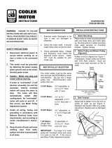
VERTICAL/HORIZONTAL INSTALLATION
Theunit is shippedforvertical installation with avertical airdis
-
chargeas showninFigure 1,butmay beconvertedto otherar
-
rangements per the following instructions.
1.Remove the panels from the blower section.
2.Remove the four Phillips machine bolts that hold the coil
and blower sections together. A bolt is located near each
corner.
3.Move the blower section to the proper location.
4.Attach the blower section to the coil section with the ma-
chine bolts removed in Step 2.
5.Before replacing thepanel,seeDuctConnection and Drain
Connection.
6.Replace the panels.
DUCT CONNECTIONS
All ducts should be designed and installed in accordance with
applicable national and/or local codes.
Ducts should be sized no smaller than the duct flanges on the
unit or the accessory electric heater (if used). Refer to the unit
dimensions(Figure7) andthe heaterdetail(Figure 2) forthese
sizes.
The field installed air plenum and return air grille accessories
shouldbe usedin placeofductwork onlywhena freeblow/free
return application is practical.
REFRIGERANT MAINS
Many service problems can be avoided by taking adequate pre
-
cautionstoprovideaninternallycleananddrysystem,andbyus
-
ing procedures and materials that conform with established
standards.
Hard drawn coppertubing should be used where noapprecia-
ble amount of bending around pipes or other obstructions in
necessary. Use long radius ells wherever possible. If soft cop-
per is used, care should be taken to avoid sharp bends which
may cause a restriction.
Pack fiberglass insulation anda sealing materialsuch as Per-
magum aroundrefrigerant lineswhere theypenetrate awall to
reduce vibration and to retain some flexibility.
Support all refrigerant lines at minimum intervals with suitable
hangers, brackets or clamps.
Braze all copper to copper joints witH Sil-Fos 5 or equivalent
brazing material. Do not use soft solder.
Never braze or solder liquid and suction lines together. The
complete suction line should be insulated with no less the
"
(12mm) ARMAFLEX or equivalent.
If it is desirable to tape or wire the liquid and suction lines to
-
gether for support purposes, they must be completely insu
-
lated from each other.
INSTALLING REFRIGERANT MAINS
The units are evacuated and dehydrated at the factory and
shipped with a holding charge of Refrigerant-22. The suction
and liquid connections are sealed with copper disks.
WARNING: Provisions for recovering refrigerant releases
must be available during all phases of installation,
leak testing and charging. Do NOT release refrig
-
erantinto theatmosphere.ASchradervalveispro
-
vided on the coil header for recovering refrigerant
holding charge.
If the unit has already lost its holding charge, it should be leak
tested and the necessary repairs should be made. If the unit
has maintained its holding charge, you can assume that it has
no leaks and proceed with the installation.
Make sure the refrigerant in the lines has been recovered,
then drill a small hole through the discs to prevent any inter
-
nal pressure from blowing them off and to allow the flow of
dry nitrogen through the connections when unbrazing the
closures.
Unitary Products Group 3
035-12124-000 Rev. A (0501)
FIG 1 - VERTICAL AND HORIZONTAL APPLICATION
FIG. 2 - ELECTRIC HEATER ACCESSORY
(489)
(565)
(25)

NOTE: To minimize the possibility of system failure due to dirt
andmoisture,afilter-driermustbeinstalledineachliq
-
uid line as close to the evaporator as possible. Filter-
driers are not supplied with the evaporator blowers.
They are supplied with thematching condensing sec
-
tions.
The temperature required to make or break a brazed joint is
sufficiently high to cause oxidation of the copper unless an
inert atmosphere is provide.
CAUTION:Drynitrogenshouldflowthroughabrazedjointatall
times when heat is beingapplied anduntil the joint
has cooled.
The liquid, suction and drain connections inside the unit must
be piped to the outside. Refer to Unit Dimensions for loca
-
tions of the access openings in the unit panel.
Protective grommets are supplied by the factory for field
placement into these access openings.
The blower units are shipped with the coil section side pan
-
els suitable for right hand piping connections when viewed
from the return air side of the unit.
The refrigerant piping and the condensate drain connection
may be routed through either side of the unit.
If left hand piping is required, the two panels on the right side
of the coil section can be interchanged with the single panel
on the left hand side of the coil section.
When left hand piping connections are installed, the suction
line must be insulated to prevent moisture from condensing
and being carried into the blower section.
EXPANSION VALVE BULB
The expansion valve bulb must be fastened in a 4 o'clock po-
sition to the suction line outside the cabinet after the piping
connections have been made. Use the clamps supplied with
the valve.
DRAIN CONNECTION
The drain line MUST be trapped because the coil is located
on the negative side of the supply air blower. It must also be
protected from freezing temperatures.
A
" (22.2mm) OD stub connection is provided within the
cabinet on both ends of the condensate drain pan for either
left hand or right hand piping connections. Refer to Figure 3
for recommended drain piping.
The drain line is usually located on the same end of the coil
section as the refrigerant connections. The line should be in
-
sulated where moisture drippage will be objectionable or
cause damage to the area. Seal the unused drain connec
-
tion with a suitable mastic.
The 3" (76mm) dimension must equal or exceed the nega
-
tive static pressure developed by the supply air blower. If it
does not, condensate will not drain properly and may over
-
flow the drain pan. The trap must be at least 2" (50mm) deep
to maintain a water seal under all operating conditions, espe
-
cially during blower start-up.
SUPPLY AIR BLOWER ADJUSTMENT
The RPM of the supply air blower will depend on the re
-
quired airflow, the unit accessories and the static resistances
of both the supply and the return air duct systems. With this
information, the RPM for the supply air blower can be deter
-
mined from the blower performance in Table 5
Knowing the required blower RPM and the blower motor HP,
the setting (turns open) for the supply air motor pulley can be
determined from Table 3..
Each motor pulley has:
1.A threaded barrel with two flats (or notched recesses) 180
degrees apart.
2.A movable flange with one set screw.
After the movable flange has been rotated to the proper
number of “turns open”, the set screw should be tightened
against the flat on the barrel to lock the movable flange in
place. If the pulley includes a locking collar, the locking collar
must be loosened to adjust the setting of the movable
flange.
Note the following:
1.The supply airflow must be within the limitations shown in
Table 2.
2.All pulleys can be adjusted in half-turn increments.
3.The tension on the belt should be adjusted for a deflection
of
" (5mm)per foot (305mm)of belt span withan applied
force of approximately 3 lbs (1.4kg). This adjustment is
madeby movingtheblower motormountingplate. Referto
Figure 4. Turning the adjustment bolt (B) moves the motor
mounting plate up or down. Note - Never loosen the two
nuts (C). Four hex nuts (A) have to be loosed to move the
mounting plate and retightened after the mounting plate
has been moved to the proper position.
4 Unitary Products Group
035-12124-000 Rev. A (0501)
FIG 3 - RECOMMENDED DRAIN PIPING
(76)
(50)
TURNS OPEN*
BLOWER DRIVE RANGE (RPM)
615-800
5 615
4 652
3 689
2 726
1 763
0 800
* Pulleys can be adjusted in half-turn increments.
TABLE 3 - SUPPLY AIR BLOWER MOTOR PULLEY
ADJUSTMENT

4.All pulleys are factory aligned.
5.All supply air motor pulleys are factory set at two “turns
open.”
After the supply air blower motor is operating, adjust the resis
-
tances in both the supply and the return duct systems to bal
-
ancetheair distributionthroughout theconditioned space.The
job specifications may require that this balancing be done by
someone other than the equipment installer.
Tocheckthesupply air airflowafterthe theinitialbalancing has
been completed:
1.Drill twoholes
" (8mm) dia.in the side panel as shown in
Figure 5.
2.Insert at least 8" (200mm) of
" (6.3mm) O.D. tubing into
each of these holes for sufficient penetration into the air
flow on both sides of the evaporator coil.
NOTE: The tubes must be inserted and held in a position per
-
pendicular to the air flow so that velocity pressure will
not affect the static pressure reading.
3.Using aninclinedmanometer,determinethe pressure drop
across a dry evaporator coil. Since the moisture on an
evaporator coil may vary greatly, measuring the pressure
dropacross awet coilunder field conditionswould beinac
-
curate. To assure a dry coil, the refrigerant system should
be de-energized while the test is being run.
4.Knowing thepressuredrop across adry coil,theactual air
-
flow through the unit can be determined from the curve in
Figure 6.
If the airflow is above or below the specified valve, the supply
air motor pulley may have to be readjusted. After one hour of
operation, check the belt and pulleys for tightness and align
-
ment.
WARNING:Failure toproperly adjustthetotalsystem airquan
-
tity can result in extensive blower damage.
Afterreadings havebeenobtained,remove thetubesand seal
up the drilled holes in the side panel with
" (8mm) dia. dot
plugs(P/N029-13880)availablethroughnormalpartsordering
procedure.
Unitary Products Group 5
035-12124-000 Rev. A (0501)I
Blower Motor
HP/kW
Power Supply FLA LRA
Maximum
Fuse Size* Amps
Maximum
Wire Length* * Ft.(m)
3 / 2.2 380/415-3-50 5.2 37.0 10 400 (122)
* Dual element, time delay fuses.
** Based on three 60° C, 14 AWG, insulated copper conductors in steel conduit and a 3% voltage drop.
TABLE 4 - ELECTRICAL DATA
NOTE; SHUT DOWN THE REFRIGERANT SYSTEM BEF-
ORE TAKINGANY TEST MEASUREMENTSTO AS-
SURE A DRY EVAPORATOR COIL
FIG 4 - TYPICAL MOTOR MOUNTING ASSEMBLY
FIG 5 - HOLE LOCATIONS
(559)
(8)
(8)
(254)
(457
TO DETERMINE PRESSURE DROP READINGS
ACROSS THE DRY EVAPORATOR
FIG 6 - PRESSURE DROP VS SUPPLY AIRFLOW

6 Unitary Products Group
035-12124-000 Rev. A (0501)I
SUPPLY AIR BLOWER PERFORMANCE
1
- (CFM)
BLOWER
SPEED
RPM
AIRFLOW
ESP
2
(IWG)
OUTPUT
(BHP)
INPUT
(kW)
ESP
2
(IWG)
OUTPUT
(BHP)
INPUT
(KW)
ESP
2
(IWG)
OUTPUT
(BHP)
INPUT
(kW)
ESP
2
(IWG)
OUTPUT
(BHP)
INPUT
(kW)
ESP
2
(IWG)
OUTPUT
(BHP)
INPUT
(kW
4800 CFM 5400 CFM 6000 CFM 6600 CFM 7200 CFM
600 0.46 1.44 1.34 0.30 1.68 1.56 0.11 1.96 1.80 - - - - - -
625 0.55 1.54 1.43 0.40 1.79 1.64 0.22 2.08 1.90 0.01 2.41 2.20 - - -
700 0.84 1.83 1.68 0.70 2.12 1.94 0.54 2.43 2.22 0.36 2.77 2.54 0.12 3.12 2.82
800 1.26 2.38 2.17 1.15 2.70 2.47 1.00 3.03 2.74 0.83 3.37 3.05 0.62 3.75 -
900 1.70 2.95 2.68 1.63 3.30 2.99 1.52 3.67 - - - - - - -
SUPPLY AIR BLOWER PERFORMANCE
1
- (m
3
/s)
BLOWER
SPEED
RPM
AIRFLOW
ESP
2
(Pa)
OUTPUT
(kW)
INPUT
(kW)
ESP
2
(Pa)
OUTPUT
(kW)
INPUT
(kW)
ESP
2
(Pa)
OUTPUT
(kW)
INPUT
(kW)
ESP
2
(Pa)
OUTPUT
(kW)
INPUT
(kW)
ESP
2
(Pa)
OUTPUT
(kW)
INPUT
(kW)
2.26 m
3
/s 2.55 m
3
/s 2.83 m
3
/s 3.11 m
3
/s 3.40 m
3
/s
600 114 1.07 1.34 74 1.25 1.56 27 1.46 1.80 - - - - - -
625 136 1.15 1.43 99 1.33 1.64 55 1.55 1.90 3 1.08 2.20 - - -
700 208 1.36 1.68 174 1.58 1.94 134 1.81 2.22 89 2.06 2.54 30 2.32 2.82
800 312 1.77 2.17 285 2.01 2.47 248 2.26 2.74 206 2.51 3.05 154 2.79 -
900 422 2.20 2.68 404 2.46 2.99 311 2.73 - - - - - - -
1
Unit resistance is based on a wet evaporator coil and clean filters.
2
Availablestatic pressure in IWG (Pa)to overcome the resistance ofthe duct system andany accessories added to the unit.Refer to Table 6 for the resistance of these
accessories and to Table 7 for additional motor and drive data
NOTE: Motors can be selected to operate into the service factor because they are located in the moving air stream, upstream of any heating device.
LEGEND:
TABLE 5 - BLOWER PERFORMANCE
RPM range for standard
factory-mounted drive components.
Exceeds the output limitation of the standard
factory-mounted blower motor.
TABLE 6 - ACCESSORY STATIC RESISTANCE (IWG)
ACCESSORY
EXTERNAL STATIC PRESSURE DROP RESISTANCE
IWG/pA
BLOWER CFM/m
3
/s
4800 /
2.26
5400 /
2.55
6000 /
2.83
6600 /
3.11
7200 /
3.40
Electric
Heat
10kW 0.04 / 10 0.05 / 12 0.06 / 15 0.08 / 20 0.10 / 25
16kW 0.07 / 18 0.09 / 21 0.11 / 27 0.14 / 35 0.17 / 42
26kW 0.13 / 32 0.16 / 40 0.20 / 50 0.24 / 60 0.29 / 72
36kW 0.20 / 50 0.24 / 60 0.29 / 72 0.35 / 87 0.42 / 106
Supply Air Plenum 0.03 / 8 0.04 / 10 0.05 / 12 0.06 / 15 0.07 / 18
Return Air Grille 0.04 / 10 0.05 / 12 0.06 / 15 0.07 / 18 0.08 / 20
Hot Water Coil 0.18 / 45 0.22 / 55 0.26 / 64 0.30 / 74 0.34 / 84
Steam Coil 0.15 / 37 0.18 / 45 0.22 / 55 0.26 / 64 0.30 / 74
* Add these pressures to the ESP values in the respective blower performance table.

Unitary Products Group 7
035-12124-000 Rev. A (0501)
FIG 7 - UNIT DIMENSIONS AND CLEARANCES
UNIT
ACCESSORIES
•ELECTRIC HEATER
Add 15" (381mm) to Unit Height when using 10, 16, 26 or 36kW Heater
•SUPPLY AIR PLENUM
Add 27" (686mm) to Unit Height when used
•BASE
Add 24" (610mm) to Unit Height when used
MINIMUM CLEARANCES (in./mm)
Side with RETURN AIR opening - 24 / 610
Side with SUPPLY AIR opening - 24 / 610
1
Side with PIPING CONNECTIONS - 61 / 1549
2
Side opposite PIPING CONNECTIONS - 26 / 660
3
Bottom -
4
NOTES:
1
Overall dimension of the unit will vary if an electric heater, a supply air plenum or a base is used.
2
This dimension is required for removal of the DX coil. Only 26" (660mm) is required for normal serv
-
icing.
3
If the DX coil has to be removed, this dimension is required to loosen screws that secure the coil to
the unit frame. This dimension will also be required for blower motor access if the piping
connections are made on the opposite side of the unit.
4
Allow enough clearance to trap the condensate drain line.
All dimensions are in millimeters and inches. They are sub-
ject to change without notice. Certified dimensions will be
provided upon request.

MOTOR SPECIFICATIONS
•1450 RPM
•380/415-3-50
•Solid base
•56 Frame
•Inherently protected
•Permanently lubricated
ball bearings
MAINTENANCE
FILTERS—Thefiltersmustbereplacedasoftenasnecessary
to assure good air flow and filtering action.
EVAPORATORCOIL—Donotallowdirttoaccumulateonthe
evaporatorcoilorotherpartsoftheevaporatoraircircuit.Clean
as often as necessary to assure good system performance.
Use a brush, vacuum cleaner attachment or other suitable
means.
LUBRICATION — The bearings for the blower shaft and the
blower motors are permanently lubricated and should not re
-
quire additional lubricant.
DRAIN PAN — The drain pan should be inspected regularly
to assure proper drainage.
BELTS — Maintain belt tension to extend belt life. Replace
when signs of failure begin to appear.
POWER AND CONTROL WIRING
Install electrical wiring in accordance with appli
-
cable national, local and municipal codes. The
unit should be grounded in accordance with
these codes.
Route the power wires into the unit through one
of the
" (22.2mm) dia.knockouts in the panel
with the supply air opening and connect them to
the terminals on blower motor contactor 10M.
Route the control wires into the unit through the
other
" (22.2mm) dia.knockout and connect
them to the terminals on block 4TB. Refer to
the unit drawing in Figure 7 for the locations of
these knockouts.
If the unit includes an electric heat accessory,
route the power wires into heater control box in-
stead of the unit. Refer to the electric heat in-
structions for additional installation information.
Refer to Table 4 to size the disconnect switch,
the power wiring and the fuses. Refer to Figure
8 for typical field wiring.
NOTE:Three phasemotor rotationmay beincor-
rect when the unit is first started up. Re
-
verse phase (leads L1 and L2) at
contactor to obtain the correct rotation.
FIG 8 - TYPICAL FIELD WIRING (Cooling only)
TERMINALSONBLOCK3TBOF
THE BLOWER UNIT
TERMINALS ON
1-STAGE COOLING
THERMOSTAT
2TH0870124
Motor
(HP/kW)
Blower
Range
(RPM)
Adjustable Motor Pulley Fixed Blower Pulley Belt
Pitch Dia
(In./mm)
Bore
(In./mm)
Pitch Dia.
(In./mm)
Bore
(In./mm)
Designation
Pitch Lg.
(In./mm)
3 / 2.2 615/800
3.4 - 4.4 / 86
- 112
/ 22.2
8.0 / 203 1 / 25 A54 55.3 / 1405
TABLE 7 - BLOWER MOTOR AND DRIVE DATA
Subject to change without notice. Printed in U.S.A
Copyright by York International Corporation
5005
York
Drive
035-12124-000 Rev. A (0501)
Supersedes: 550.39-N5YI (894)
Products
Group
OK
73069
/