Page is loading ...

Grill Guide
Grill Modular Model B09SMG1-3F
LP Gas Grill
Stop!
Missing a part? No need to go back to SAM'S CLUB!
SAM'S CLUB does not stock parts for this item at the Club, but our grill team is here to
help you. If you need parts, whether they are missing or damaged,
please call our Toll Free Help Line
1-800-933-0527
Call us between 8:30 AM to 5:00 PM Central Time, Monday through Friday.

Safety Precautions
Always read and follow all DANGER, WARNING, AND FOR YOUR SAFETY notices in this Grill
Guide. Failure to do so may result in serious injury, death, fire, or an explosion causing damage to
property.
1. Grill installation must conform with local codes, or in their absence, with either the National Fuel
Gas Code, ANSI Z223.1/NFPA 54, or CAN/CGA B149.1, Natural Gas and Propane Installation
Code, or Propane Storage and Handling Code, B149.2.
2. This gas grill, when installed, must be electrically grounded in accordance with local codes, or, in
the absence of local codes, with the National Electrical Code, ANSI/NFPA 70, or the Canadian
Electrical Code, CSA C22.1. Keep any electrical cords away from hot surfaces.
3. This gas grill shall be used outdoors only, and shall not be used in a building, garage, or any other
enclosed area.
4. This gas grill is not intended to be installed in or on recreational vehicles and/or boats.
5. Never use any other type of fuel for this grill other than that specified on the name plate attached to
the grill or the cover of this Grill Guide.
6. Only use the pressure regulator with a type 1 connector that is supplied with this gas grill.
7. Before each use, check the gas hose for excessive abrasion or wear, or cuts. Replace a hose
assembly showing those signs with the hose assembly specified in the parts list before using the
grill.
THIS GRILL IS FOR OUTDOOR USE ONLY.
If stored indoors, then detach and leave propane cylinder outside.
WARNING
1. Do not store or use gasoline or other flammable liquids or vapors in the
vicinity of this or any other appliance.
2. An LP cylinder not connected for use shall not be stored in the vicinity of
this or an
y
other a
pp
liance.
!
DANGER
If you smell gas:
1. Shut off gas to the appliance.
2. Extinguish any open flame.
3. Open lid.
4. If odor continues, keep away from the appliance and immediately call
y
our
g
as su
pp
lier or
y
our fire de
p
artment.
!
WARNING
Combustion by-products produced when using this product contain
chemicals known to the State of California to cause cancer, birth defects, and
other reproductive harm.
!
TO THE INSTALLER OR PERSON ASSEMBLING THIS GRILL:
Leave this Grill Guide with the consumer.
TO THE CONSUMER:
Retain this Grill Guide for future reference.

3
Table of Contents
Safety Precautions……….……………………………..……………...…………...…… 2
Table of Contents…………………….…………………………………..……….……...3
Warranty……………………………….………………………………………….…….. 4
Customer Support Center……………….………………………………………….…….4
Assembly Instructions...…………………………………………………………..…..5-18
General Information and Operation………………..………………………………..19-31
Trouble Shooting Guide……………………………………………….................……..32
Frequently Asked Questions……………………………………………………………33
Write down here and keep for future
reference
Date of Purchase: _________________
Serial Number: ___________________
The serial number may be found on the placard located
on the back of the grill
Model Number: B09SMG1-3F
Sam’s Club
608 Southwest 8
th
Street
Bentonville, AR 72712
1-888-746-7726
Visit us at: www.samsclub.com

Limited Warranty
The manufacturer warrants to the original
consumer-purchaser that this product shall be free
from defects in workmanship and materials under
normal and reasonable use when assembled and
operated according to this Grill Guide from date of
purchase as follows:
One year except as noted below:
Stainless Steel Burners – 3 years
Stainless Steel Parts except Burners, Grates,
Warming Rack, and Heat Diffusers - 5 years
The manufacturer will, at its option, refinish or
replace any product or part found to be defective
during the limited warranty period. There may be a
shipping charge. The manufacturer may require you
to return the part(s) claimed to be defective for its
inspection, freight or postage prepaid. Contact our
Customer Support Center as shown below before
returning any part(s).
Additional information can be obtained by writing:
Barbecue Grills
Grill Registration
1350 Munger Road
Bartlett, IL 60103
The manufacturer will require reasonable proof of
purchase. We strongly recommend you keep your
sales receipt and register your grill. You can attach
your receipt to this guide.
This limited warranty does not cover the cost of any
inconvenience or property damage due to failure of
the product and does not cover damage due to misuse,
abuse, alteration, improper or failure to perform
normal and routine maintenance, discoloration,
scratches, rust, accident, damage arising out of
transportation of the product, or normal wear and tear.
This limited warranty will not apply to any grill used
for commercial use.
This limited warranty is the sole warranty given by
the manufacturer and is in lieu of all other warranties;
express or implied, including implied warranty of
merchantability or fitness for a particular purpose.
Neither manufacturer dealers nor the retail
establishment selling this product have any authority
to make any warranties or to promise remedies in
addition to or inconsistent with those stated above.
This limited warranty applies only to products sold at
retail, and is not transferable.
The manufacturer's maximum liability, in any event,
shall not exceed the purchase price of the product
paid by the original consumer-purchaser. Some states
do not allow the exclusion or limitation of incidental
or consequential damages. Therefore, the above
limitations or exclusions may not apply to you. This
warranty gives you specific legal rights and may also
have other rights, which vary from state to state
Customer Support Center
Thanks for purchasing a Member’s Mark Grill. We’re here to help you maximize your enjoyment and
appreciation of your new grill. Please don’t hesitate to contact us should you have any questions regarding
assembly, performance, warranty, or accessories. We have a full line of replacement parts available. Please
have your model number ready before you contact us. We’re here to serve You!
• If you need assistance or to order parts: Call 1-800-933-0527, send a FAX to 1-630-540-7099, or email us at
.
• Business hours: Monday through Friday; 8:30AM-5:00PM Central Time.
• Visit us on the web at: www.omahagrills.com
4

Assembly Instructions
This page will give you an overview of information to assemble your grill. The following pages will show in
step-by-step detail on how to do so. We offer the following suggestions to make your grill assembly as easy as
possible.
1.) Read through the entire Assembly Instructions before you begin.
2.) Choose an area large enough to comfortably lay out all the parts and hardware with enough
room to easily
maneuver.
3.) Have an area with a non-abrasive surface where you can lay parts without scratching them.
4.) This modular grill is heavy. Use caution, and enough people, to remove the modular grill from the carton
and pallet on the bottom.
5.) Lay all parts and hardware out and ensure you have everything listed on the Parts and Hardware page before
you begin assembly. See the Customer Support Page for contact information should any parts be damaged
or missing.
6.) The propane tank for this grill is sold separately. See the LP Gas and Cylinder Information later in this
guide.
WARNING
Failure to follow all Danger,
Warnings, and For Your Safety
notices in this Grill Guide may
result in serious bodily injury or
death, or in a fire or an explosion
causing damage to property.
CAUTION
Perform the Leak Test explained
later in this Grill Guide before
operating your grill.
!
!
Manufacturer Information:
Dongguan Xin Cheng Hardware Manufacturing Co., Ltd.
Jiuxiang Industrial Area ,Qingxi Town ,Dongguan City,
Guang Dong Province , China 523646
B
09S
M
G
1-
3
F
5

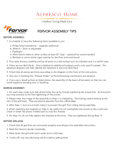
B09SMG1-3F Parts Diagram - 2009
C7
D9
D10
D12
D13
C1
C2
C3
C4
C5
C6
C8
C9
C10
C11
C12
C13
C14
C15
C16
C17
C18
C19
C20
C21 C22
C23
C24
C25
C26
D14
D15
D11
B41
B42
B21
B22
B23
B24
B28
B29
B34
B30
B31
B33
B32
B36
B37
B40
B38 B39
B43
B44
D3
D7
D4
B35
D6
D5
B45
D2
D1
B26
B27
B25
B46
B4
B5
B14
B18
B19
B15
B20
B16
B17
B13
B12
B11
B10
B9
B8
A3
A1
A2
A4
A5
A6
A7
A8
A9
A10
B6
B7
D8
B2
B1
B3
6

A1 Hood Assembly (Large) B26 Rotisserie Fork C16 Cabinet Right Door
Assembly
A2 Hood Assembly (Small) B27 Rotisserie Counter weight C17 Door Handle
A3 Heat Insulator For Lid Handle B28 Rotisserie Fork Bushing Assembly C18 Cylinder Tray Assembly
A4 Thermometer B29 Light Button C19 Cylinder Heat Shield
A5 Thermometer Seat B30 Igniter Protection Case A C20 Cabinet Shelf
A6 Hood Bolt B31 Igniter Protection Case B C21 Cabinet Shelf Left Support
A7 Hood Nut (Long) B32 Electronic Igniter Cap C22 Cabinet Shelf Right Support
A8 Hood Nut (Short) B33 Electronic Igniter C23 Locking Swivel Caster
A9 Hood Handle Assembly (Large) B34 Firebox Control Panel C24 Swivel Caster
A10 Hood Handle Assembly (Small) B35 Griddle C25 Manual Igniter
B1 Firebox Assembly B36 Large Back Burner Cover C26 Regulator and Hose Support
Ring
B2 Regulator and Hose B37 Small Back Burner Cover D1 Side Burner Hood Handle
B3 Gas Manifold Assembly B38
Back Burner Igniter Protection Case
D2 Heat Insulator For Side Burner
Handle
B4 Smoker Drawer Assembly B39 Electrod D3 Side Burner Hood Assembly
B5 Silicon Stopper For Hood B40 Back Burner Fuel Line D4 Side Burner Cooking Grate
B6 Large Cooking Grate B41 Flame Sensor Assembly D5 Side Burner Hood Support
B7 Small Cooking Grate B42 Back Burner Electrod Support D6 Side Burner Inside Frame
B8 Large Heat Diffuser B43 Back Burner D7 Side Burner Shelf Frame
B9 Small Heat Diffuser B44 Right Table Panel D8 Side Burner Valve
B10 "I” Burner B45 Firebox Right Outer Panel D9 Side Burner
B11 "U" Burner B46 Igniter Wire D10 Side Burner Electrod
B12 "I" Burner Electrod C1 Cabinet Bottom Panel Assembly D11 Side Burner Electrod Cap
B13 "U" Burner Electrod C2 Cabinet Front Toe Plate D12 Side Burner Grease Cup Hook
B14 Burner Support Crossbar Assembly C3 Cabinet Left Side Panel D13 Side Burner Grease Cup
B15 Grease Tray Assembly C4 Cabinet Right Side Panel D14 Side Burner Control Panel
B16 Knob Seat C5 Cabinet Back Panel D15 "S" Hook
B17 Knob C6 Cabinet Door Crossbar Assembly
B18 Warming Rack (Large) C7 Firebox Left Support
B19 Warming Rack (Small) C8 Firebox Right Support
B20 Back Shield Panel C9 Protection Washer
B21 Firebox Left Outer Panel C10 Cylinder Tray Protection Washer
B22 Firebox Left Table Assembly C11 Wire Pin
B23 Motor Support C12 Cabinet Rail
B24 Rotisserie Motor C13 Magnet Assembly
B25 Rotisserie Spit C14 Transformer Assembly
C15 Cabinet Left Door Assembly
B09SMG1-3F Parts Diagram - 2009
7

B09SMG1-3F Assembly Parts List
1.Main
Assembly…1PC
2.Small Heat
Diffusers…3PCS
3.Large Heat
Diffuser…1PC
4.Side Burner Control
Panel And Knob Seat
Assembly…1PC
5 .Side Burner
Assembly…1PC
6..Side Burner Shelf
Frame…1PC
7.Side Burner
Knob…1PC
8.Side Burner Grease
Cup Hook…1PC
9.Side Burner Grease
Cup…1PC
10.Counter
weight…1PC
11. Rotisserie
Motor…1PC
12.Rotisserie
Fork…2PCS
13.Rotisserie Spit
Bushing…1PC
14.Rotisserie
Spit…1PC
15. Large Cooking
Grate…2PCS
16.Small Cooking
Grate…1PC
17.Side Burner
Cooking Grate…1PC
18.Griddle…1 PC
19.Side Burner
Cover…1PC
20.Grill Cover…1PC
8

HARDWARE LIST
A
Phillips Head Bolt
M6x16mm
2PCS
B
Phillips Head Bolt
M4x8mm
14PCS
C
AA Battery
1PC
D
“S” Hook
3PCS
E
Screwdriver
1PC
9

STEP 2 –Install side burner shelf frame and side burner control panel using 3 Stainless philips head bolts
(M4x8mm)
Philips Head Bolt:M4x8mm
Qty:3
6
4
STEP 1 –Attach the side burner hood assembly onto the side burner shelf frame using 4 philips head bolt
as shown.
19
Philips Head Bolt:M4*8mm
Qty:4
10
6

STEP 3 –Unscrew the 2 flat head bolts( M6x16mm) ¼ inch from the upper left and right corner holes in
the left side of the firebox .The bolts extending out of the firebox sides are to attach the side shelf frame.
Then hang the Side Burner on the 2 top bolts, and secure the bottom with two more philips head bolts
(M6x12mm). Note –Make sure all bolts are threaded correctly before tightening.
STEP 4 –Attach the valve and side burner control panel assembly with two Philips bolts(M4x8mm). Then
attach the side burner control panel and main burner control panel using a Philips Head Bolt.
Philips Head Bolt:M16x16mm
Qty:2
Philips Head Bolt:M4x8mm
Qty:3
11

STEP 6 –Place Side Burner Cooking Grate(17) on top of the Side Burner (5) as shown.
STEP 5 –Open the side burner cover(6) and insert the Side Burner assembly (5). Ensure the four holes in
the side burner assembly line up with the side burner shelf frame. Then attach using 4 Phillip Head bolts.
Philips Head Bolt:M4x8mm
Qty:4
17
5
12

STEP 7 –Slide the Knob(7) on the stem. Attach the igniter wire.
STEP 8 –Insert Grease Cup Hook ( 8 ) into the bottom of side burner assembly
8
7
13

STEP 9 –Insert Grease Cup (9) onto the Side Burner Grease Cup Hook(8).
STEP 10 –Insert the 3 Small Heat Diffusers(2) and the Large Heat Diffuser(3) inside the firebox. The sides of
the Heat Diffusers fit down in-between knobs on the front and back of the firebox as shown. Insert the Large
Heat Diffuser over the large “U” burner on the right side of the firebox.
9
14
3
2

STEP 11 –Place Cooking Grates(15)(16) into firebox as shown. When using the Griddle(18), simply place
over the cooking grates
. Note- The Smaller Cooking Grate is just slightly smaller than the main cooking
grates.
STEP 12 –Assemble the Rotisserie Spit(14) in the following order: First slide the two Slide Spit Washers(20)
out .Second slide on both Rotisserie Forks(12) with the forks facing each other. Then slide on the Rotisserie
Spit Bushing (13) , one of the Spit Washers(20) and Counter Weight(10) followed them. Next screw the the
other Spit Washer(20) onto the end of spit. Finally, secure them to the middle of the spit by tightening their
thumbscrews. Note- Use caution as the forks are sharp.
18
15
16
20
13
10
12
15

STEP 13 –Slide the Rotisserie Motor(11) into place on the motor support on the right side of the firebox.
Slide the spit assembly into place by inserting the pointed end into the Rotisserie Motor(11) and placing the
bushing on the left firebox sidewall. Note - Do not use the Rotisserie Motor in rain or expose to moisture.
STEP 14–Slide the LP cylinder tray out of the cabinet by pulling the tray latch up in the vertical position.
Then place the LP cylinder on it. Be sure the LP cylinder is “OFF” by turning the hand wheel clockwise until
it stops. Be sure all burner control knobs(7) are turned to the “OFF” position. Remove the safety cap from the
cylinder valve. Center the nipple of the regulator into the cylinder and attach the regulator to the LP tank by
turning the black nut clockwise until it stops.
11
16

STEP 16 –Unscrew the electronic igniter cap. Place the “AA” Battery into the electronic igniter with the
Positive(+) end facing out . Screw the electronic igniter cap back into place on the electronic igniter.
Note - Do not dispose of batteries into fire. Batteries may leak or explode.
STEP 15 –Slide the LP cylinder tray out of the cabinet by pulling the tray latch up in the vertical position.
Unscrew the screw on the back of the cylinder tray. Then place the tank onto the sliding LP cylinder tray. Make
sure the front of the tank valve faces the front of the cabinet. Tighten the screw on the back of the cylinder tray
to secure the LP cylinder. Slide the LP cylinder tray back into the cabinet and lock in place by pushing the LP
cylinder tray latch down to a horizontal position.
17
C

STEP 18 –Remove any labels and additional packing material from the grill except the CSA label. Be sure to
clean all foam packing material out of all areas.
Congratulations! Your grill is now fully assembled. Please proceed and read the General Information and
Operation portion of the Grill Guide before operating your grill.
STEP 17 –Insert Hooks into the holes of the left side of Side Burner Shelf Frame.
18
D

General Information and Operation
Your new Member’s Mark Modular Grill has been designed and manufactured to high quality standards. It will
provide you with many years of enjoyment with a minimal amount of maintenance. Please keep in mind the
following FOR YOUR SAFETY.
OPERATION
• Your gas grill requires reasonable care during operation. It will be hot during cooking and cleaning. You
should never leave the grill unattended or move the grill when in use.
• Children should never use your gas grill. Keep younger children and pets away when in use.
• Only use your gas grill outside in a well-ventilated area. Never use indoor in any building, garage, shed, or
under any type of flammable canopy or overhang.
• Ensure your grill is on level ground and the locking casters are locked before use.
• Turn all gas valves off should the burners go out when cooking. Open the lid and wait 5 minutes before
relighting.
• Do not lean over the grill or touch the edges of the firebox or lid when in use.
• Turn the burners off, close the lid, and shut off the LP cylinder should a grease fire occur.
• Do not obstruct the flow of combustion and ventilation air to this grill.
• Keep the ventilation openings of the cylinder enclosure free and clear from debris.
• Keep the outdoor cooking gas appliance area clear and free from combustible materials, gasoline, and other
flammable vapors and liquids.
• Do not put a grill cover or other flammable material in the storage area of this grill.
• Do not use charcoal briquettes, lava rock, or any type of ceramic product in this grill.
LP Gas and Cylinder Information
Your new gas grill operates on LP (Liquid Propane) Gas. It is odorless, colorless, and non-toxic when produced.
You can smell LP gas as it has been given an odor similar to rotten cabbage for your safety.
Your grill uses the newest and safest LP Gas Cylinder.
1. A listed O.P.D. (Overfill Protection Device) must be used. This prevents
accidental gas leaks caused by overfilling of the tank. Each tank contains
a float that closes the input valve when the tank is 80% full. This allows
room for the LP gas to expand in hot temperatures. A triangular hand
wheel distinguishes this type of tank.
2. O.C.C.1 Type 1 Quick Connect Valve – provides fast tank hook-ups and requires only to be tightened by
hand. Large external threads on the outlet part of the valve distinguish this.
In addition, the LP tank you use with your grill must meet the following requirements
1. Required Measurements: 12-1/2” (317mm) in diameter and 18-1/2” (472mm) in height.
2. 20-pound (9.1kg) propane cylinder.
3. Constructed and marked with U.S. Department of Transportation (D.O.T.) for the US or CAN/CSA-B339,
Cylinders, Spheres and Tubes for Transportation of Dangerous Goods; and Commission, for Canada.
4. A safety release valve.
5. A means for vapor withdrawal.
6. A collar to protect the tank valve.
7. A bottom ring for mounting.
Triangular Hand Wheel
!
WARNING
Do not attempt to use a cylinder with any other type of connection device.
19

LP CYLINDER FILLING AND EXCHANGE
Some areas only allow you to exchange your empty cylinder for a replacement that is already full. Other areas
allow you to refill your cylinder. If you are in an area where you can refill your cylinder:
1. Use only a licensed dealer.
2. The dealer must first purge a new cylinder before filling.
3. Never fill a cylinder more than 80% full by weight. Volume will vary by temperature. An empty cylinder
weighs approximately 18 pounds (8.2kgs).
4. Be sure the LP dealer checks the cylinder for leaks after filling.
5. Do not release LP gas into the atmosphere, as it can unexpectedly ignite when mixed with air.
6. Contact a LP dealer to remove LP gas from a cylinder.
7. Only exchange your cylinder for one with an O.P.D. feature as shown above.
!
LP CYLINDER LEAK TEST
A leak test should be done each time a cylinder is refilled or exchanged. Do
not smoke or use any type of flammable material in the area during this leak test.
Do not use an open flame to check for leaks.
1. Test outside in a well ventilated area.
2. Use a paintbrush and a solution of 50% liquid soap and 50% water.
3. Do not use cleaning agents and they can damage the fuel supply parts.
4. Brush liquid onto areas highlighted with arrows.
5. Bubbles indicate a leak.
!
WARNING
1. Never store any extra cylinders under or near your grill.
2. Never fill your cylinder over 80% full by weight. This may cause release of gas from the safety
relief valve.
3. If the information in points 1 and 2 above is not followed exactly, a fire causing death or serious
DANGER
Bubbles indicate a leak. In that case, call your LP dealer or fire department immediately.
FOR YOUR SAFETY
1. The gas supply must be turned off at the LP gas supply cylinder when this gas grill is not in use.
2. Storage of this gas grill indoors is permissible only if the cylinder is disconnected and removed from
the gas grill.
3. Cylinders must be stored outdoors out of reach of children and must not be stored in a building,
garage, or any other enclosed area.
WARNING
A frosty cylinder valve indicates possible gas overfill. Close the LP valve and call your dealer
immediately.
!
!
!
20
/