Page is loading ...

REV 4 - 1403060815
L-C2-193
1
INSTALLER: Leave these instructions with consumer.
CONSUMER: Retain for future reference.
ROBERT H. PETERSON CO. • 14724 East Proctor Avenue • City of Industry, CA 91746
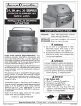
SPARK GENERATOR
REPLACEMENT KIT
Models # 3199-47, 3199-48
Fig. 1-1 Spark generator parts
Generator
Locking
ring
Ignitor
cover
Rubber
battery cap
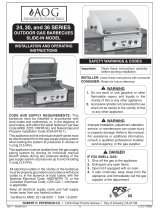
Fig. 1-2 Spark generator wires
Rear view showing
wires connected to
terminals.
Fig. 1-3 Remove battery cap
Turn ignitor cover to remove
and replace the generator
WRONG!
Fig. 1-4 Fasten ground wire
Where fi tted, ensure
that the ground wire
is securely fastened
to the manifold
mounting bolt (right
side).
Manifold
1. Ensure the grill is completely cool, the knobs are in
the off position, and the gas supply to your grill is
turned off.
2. Remove the valve knobs from the face or panel.
3. Remove the screws and fi nish washers securing the face.
4. Carefully remove the face.
CAUTION: The spark generator is attached to the face or
panel. Carefully unplug all wires from the spark
generator before pulling it away from the unit (see
Fig. 1-2).
5. Remove the battery cap by turning the ignitor cover
counter-clockwise (Fig. 1-3).
Note: Do not attempt to pull or turn the rubber cap (Fig. 1-3).
6. Hold the generator, and turn the locking ring counter-
clockwise. (It may be necessary to use pliers to get it started.)
7. Inspect the wires to make sure they are not cracked or
damaged. This can cause short-circuiting of the generator.
8. Install the new generator and new battery by following
steps 1 through 5 in reverse order.
9. Attach all wires to poles on the generator (order not critical).
Attach the ground wire, if necessary, to the manifold
mounting bolt on the right side (see Fig. 1-4). Use the nut
provided.
10. Check ignitors for spark when the generator button is
depressed.
11. Secure the face to the frame with the original face screws
and fi nish washers.
Note: When connecting the ignitor wires all terminals must be
occupied. If both of the terminals are used, no ground
wire is necessary. If using only one terminal, the second
MUST be used as a ground wire.
2-position model shown

REV 4 - 1403060815
L-C2-193
2
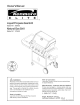
Ground point
Collector
box
Electrode
Pre-2000 Legacy
collector box
3/16"
Fig. 2-1 Collector box
TROUBLESHOOTING YOUR GRILL IGNITION SYSTEM
If you have do not have a strong spark or have no spark at
all, use the following steps to remedy the problem.
• Make sure the wires are securely plugged into the generator.
• Inspect the wires to make sure the insulation is not cracked or
frayed, and the ground wire is securely fastened to the frame.
• If you have the battery spark generator, replace the battery
with a new one.
• Check the spark gap on the electrode. It should be 3/16"
between the tip of the electrode wire and the sparking
(ground) point (see Fig. 2-1). Make sure the electrode is
secure in the collector box, and the collector box is secure
to the frame. Consult your grill installation instructions for the
position of the collector box.
• Air shutter adjustment can affect ignition. Consult your grill
installation instructions (AIR SHUTTER ADJUSTMENT) for
proper adjustment settings.
Collector
box
Post 2000 Legacy
collector box
3/16"
Collector
box
Electrode
Gourmet
collector box
5/32"
/