Assembly Instructions for Model: VM200
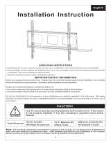
Thank you for choosing a Sanus Systems VisionMount™ wall mount. The VM200 is designed to mount up to 40″ LCD TVs weighing less
than 80 lbs [36.3 Kg] to a vertical wall. It will allow you to effortlessly tilt the TV ±20°
CAUTION: The size and weight of your television must not exceed 40” [1016 mm] diagonally and 80 Lbs [36.3 Kg]. The wall must
be capable of suporting ve times the weight of the televison plus the wall mount. Never use defective parts. Improper installation
may cause property damage or personal injury. Do not use this product for any purpose that is not explicitly specied by Sanus
Systems.
If you do not understand these directions, or have any doubts about the safety of the installation, please call a qualied contractor or contact
Sanus Systems at 800.359.5520 or www.sanus.com. Our customer service representatives can quickly assist you with installation questions
and missing or damaged parts. Replacement parts for products purchased through authorized dealers will be shipped directly to you. Check
carefully to make sure that there are no missing or defective parts. Sanus Systems can not be liable for damage or injury caused by incorrect
mounting, incorrect assembly, or incorrect use. Please call Sanus Systems before returning products to the point of purchase
NOTE: The supplied wall mounting hardware is not for metal stud or old cinder block walls. If you are uncertain about the nature
of your wall, consult an installation contractor. Sanus makes every effort to assure all necessary television mounting hardware is
included. If the hardware you need is not included please consult your local hardware store or call Sanus Systems.
Required Tools: Drill, 3/16″ drill bit, (1/2″ masonry bit for brick, concrete, or concrete block installations), wrench set, phillips screw
driver
Supplied Parts and Hardware: (All threaded fasteners are shown full size.)
Sanus Systems 2221 Hwy 36 West, Saint Paul, MN 55113 06.08.06 (6901-100024)
Customer Service: 800.359.5520. See complementary Sanus products at www.sanus.com
Wall Plate - A
Qty. 1
Left Monitor Bracket - B
Qty. 1
Right Monitor Bracket - C
Qty. 1
Lag Bolt - D
Qty. 3
Lag Bolt Washer - E
Qty. 3
Concrete Anchor - F
Qty. 3
M4 x 12 mm Bolt - G
Qty. 4
M6 x 12 mm Bolt - I
Qty. 4
M5 x 12 mm Bolt - H
Qty. 4
M6 x 35 mm Bolt - L
Qty. 4
M5 x 30 mm Bolt - K
Qty. 4
M4 x 30 mm Bolt - J
Qty. 4
M6 Washer - Q
Qty. 4
M4 Lock Washer - M
Qty. 4
M6 Spacer - S
Qty. 4
M4/M5 Spacer - R
Qty. 4
M4/M5 Washer - P
Qty. 4
M6 Lock Washer - O
Qty. 4
M5 Lock Washer - N
Qty. 4

Step 1: Mount Monitor Brackets to a television with a at back
NOTE: For televisions with a curved back, or an obstruction near the threaded insert see Step 2.
Determine the diameter of the Bolt (G,H,I) your TV requires by hand threading them into the threaded insert on the back of the TV. If you
encounter any resistance stop immediately.
Once you have determined the correct diameter, see the appropriate Diagram below, thread the Bolt through the appropriate Lock Washer
(M,N,O), corresponding Washer (P,Q), Monitor Bracket (B,C), and nally into the TV.
Make sure the Monitor Brackets (B,C) are vertically centered and level with each other.
Tighten the Bolts (G,H,I) securing the Monitor Brackets (B,C) to the monitor.
M4
Diameter Bolt
M6
Diameter Bolt
M5
Diameter Bolt
P
C
M
G
P
C
N
H
Q
B
O
I
Diagram 1
Tension
Knob
Tension
Knob
NOTE: If the horizontal distance between the
threaded inserts on the back of the television
is greater than 8-1/8 inches [206 mm] but less
than 11-1/8 inches [282.5 mm], the locations of
the Monitor Brackets (B & C) may be reversed
from right to left. If the Monitor Brackets
are reversed, the Tension Knobs must be
removed and reinstalled so that they are still
facing out.

Step 2: Mount Monitor Brackets to a television with a curved back or an obstruction near the threaded insert
Determine the diameter of the Bolt (J,K,L) your TV requires by hand threading them into the threaded insert on the back of the TV. If you
encounter any resistance stop immediately.
Once you have determined the correct diameter, see the appropriate Diagram below, thread the Bolt through the appropriate Lock Washer
(M,N,O), the corresponding Washer (P,Q), the Monitor Bracket (B,C), a Spacer (R,S), and nally into the TV.
Make sure the Monitor Brackets are vertically centered and level with each other. See the appropriate Diagram below.
Tighten the Bolts (J,K,L) securing the Monitor Brackets (B,C) to the monitor.
M6
Diameter Bolt
M5
Diameter Bolt
M4
Diameter Bolt
P
C
M
J
R
P
C
N
K
R
Q
B
O
L
S
Diagram 2
Tension
Knob
Tension
Knob
NOTE: If the horizontal distance between the
threaded inserts on the back of the television
is greater than 8-1/8 inches [206 mm] but less
than 11-1/8 inches [282.5 mm], the locations of
the Monitor Brackets (B & C) may be reversed
from right to left. If the Monitor Brackets
are reversed, the Tension Knobs must be
removed and reinstalled so that they are still
facing out.

Step 3: Mounting the Wall Plate - wood stud, brick, solid concrete and concrete block mounting options are provided
Wood Stud Installation:
CAUTION:
Do not over tighten the Lag Bolts. Tighten Lag Bolts (D) only until the Lag Bolt Washer (E) is pulled rmly against the Wall Plate
(A). If there is a layer of drywall or other material, this drywall or other material may not exceed 5/8 inch [15.8 mm] in thickness. Failure to heed
this caution may result property damage and/or personal injury
.
Use the Wall Plate as a template mark a location on the wall, one in the top row of slots and the other in the corresponding slot in the
bottom row. Pre-drill a 2.5” deep hole into the wood stud by using a 3/16” drill bit, making sure wall the Wall Plate is oriented to the at
surface is against the wall. Attach the Wall Plate to the wall using two Lag Bolts (D) and two Lag Bolt Washers (E). See Diagram 3A for
assistance.
Brick, solid concrete and concrete block installation:
Use the Wall Plate (A) as a template to mark 3 locations on the wall. Two in the top row of slots and one more centered in the bottom
row.
CAUTION: Always locate Concrete Anchors (F) in the brick, block, or concrete. Never drill into the mortar between blocks.
Make sure the Concrete Anchor is seated ush with the concrete surface even if there is a layer of drywall or other material.
This drywall or other material may not exceed 5/8 inch [15.8 mm] in thickness. Failure to heed this caution may result in property
damage and/or personal injury.
Carefully pre-drill a 2.5” deep hole with a 1/2” masonry drill bit. Insert a Concrete Anchor (F) into each pre-drilled hole so it is ush with the
concrete/brick surface, even if there is a layer of drywall or other material in front; then, attach the Wall Plate (A) to the wall using three
lag Bolts (D) an three Lag Bolt Washers (E). See Diagram 3B for assistance
Step 4: Attach Monitor to Wall Plate
CAUTION: Some televisions may require two people to lift. Sanus is not responsible for personal injury or product damage.
Rotate the Latch Handle into its most open position and hang the hooks of the Left and Right Monitor Brackets (B,C) over the tab on the
top of the Wall Plate (A) as shown in Diagram 4A.
Once the Monitor Brackets (B,C) are attached to the Wall Plate, rotate the Latch Handles on each Monitor Bracket until they click into
place. The tip of the Latch Handle should now be tucked up behind the tab on the bottom of the Wall Plate as shown in the Detailed View
of Diagram 4B.
You may place a padlock through the hole in the bottom of the latch handle if you wish to add security to the installation.
CSAV, Inc. and its afliated corporations and subsidiaries (collectively, “CSAV”), intend to make this manual accurate and complete. However, CSAV makes no claim that the information contained herein
covers all details, conditions, or variations. Nor does it provide for every possible contingency in connection with the installation or use of this product. The information contained in this document is subject to
change without notice or obligation of any kind. CSAV makes no representation of warranty, expressed or implied, regarding the information contained herein. CSAV assumes no responsibility for accuracy,
completeness or sufciency of the information contained in this document.
Diagram 3A
E
A
D
Diagram 3B
E
A
F
D
Diagram 4B
Diagram 4A
Latch
Handle
Top tab of
Wall Plate
(A)
Bottom tab of
Wall Plate
(A)
Hole for
Padlock
Tip of
Latch Handle
B,C
/