
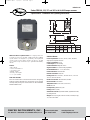
Series DDB 88, 132, 177 and 265 in-lb On/Off Damper Actuator
Specifications - Installation and Operating Instructions
Bulletin V-20
DWYER INSTRUMENTS, INC.
Phone: 219/879-8000 www.dwyer-inst.com
P.O. BOX 373 • MICHIGAN CITY, INDIANA 46361, U.S.A. Fax: 219/872-9057 e-mail: info@dwyer-inst.com
DDB Series Direct Coupled Actuators are non-spring return actu-
ators that are perfect for positioning of dampers and valves in HVAC
systems. Actuators are designed to accept floating control signals and
come in a variety of power supplies. Actuators produce 88 to 265 in-lb
(10 to 30 Nm) of torque. Contact factory for optional internal auxiliary
switches.
Features
• Direct mount.
• Actuator travel indicator.
• Overload protection.
• Manual override.
• Floating control signal.
• 60,000 cycles nominal.
SPECIFICATIONS
Power Requirements: 110 VAC, 24 VAC, ±10%, 50/60 Hz,
single phrase. Optional 230 VAC.
Power Consumption: 5.5 VA.
Control Input: On/off or floating.
Overload Protection: Magnetic clutch.
Angle of Rotation: 95° (mechanically adjustable).
Fits Shaft Diameter: 0.4˝ - 0.75˝ (10-20 mm).
Position Indication: Visual indicator.
Direction of Rotation: CW/CCW.
Running Time: 88 in-lb: 66 sec., 132 in-lb: 90 sec., 177 in-lb:
110 sec.; 265 in-lb:143 sec.
Electrical Connection: Terminal block, 18 AWG.
Manual Override: Push button.
Temperature Limit: -22 to 122°F (-30 to 50°C).
Sound: <45 dB.
Life Expectancy: 60000 full cycles.
Housing: NEMA 2 (IP42).
Standard Accessories: (2) imitative baffles, (2) baffle setscrews,
(1) setting bracket.
Weight: 2.87 lb (1.3 kg) 88, 132 in-lb models; 3.68 lb (1.67 kg)
177, 265 in-lb models.
FUNCTION TESTING
Press the manual button on the back of the actuator. The gearing
inside the actuator will break away. The damper can be operated
manually while pressing the manual button. DO NOT OPERATE
WHEN POWER IS ON!
F
A
B
D
E
C
10 Nm & 15 Nm
(88 in-lb) (132 in-lb)
20 Nm & 30 Nm
(177 in-lb) (265 in-lb)
4-17/64
(108.35)
4-57/64
(124.22)
6-55/64
(174.23)
7-23.32
(196.06)
2-49/64
(70.25)
2-23/32
(69.06)
1-35/32
(39.19)
1-1/32
(26.19)
1-15/64
(31.35)
1-25/64
(35.32)
Size A B C D E F
V-20:Model PHO-1 12/13/10 11:28 AM Page 1

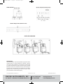
WIRING DIAGRAM
(Normal model)
Standard setting bracket (dimension in mm)
MAINTENANCE
Upon final installation of the Series DDB Non-Spring Return Direct
Coupled Actuator, no routine maintenance is required. A periodic
check of the system calibration is recommended. The Series DDB
is not field serviceable and should be returned if repair is needed
(field repair should not be attempted and may void warranty). Be
sure to include a brief description of the problem plus any relevant
application notes. Contact customer service to receive a return
good authorization number before shipping.
(Models with optional auxiliary switch)
INSTALLATION DIAGRAM
DWYER INSTRUMENTS, INC.
Phone: 219/879-8000 www.dwyer-inst.com
P.O. BOX 373 • MICHIGAN CITY, INDIANA 46361, U.S.A. Fax: 219/872-9057 e-mail: info@dwyer-inst.com
©Copyright 2010 Dwyer Instruments, Inc. Printed in U.S.A. 12/10 FR# RB-443451-20 Rev. 1
V-20:Model PHO-1 12/13/10 11:28 AM Page 2
-
 1
1
-
 2
2


Ask a question and I''ll find the answer in the document
Finding information in a document is now easier with AI
Related papers
-
Dwyer Series DDB & DDD User manual
-
-
-
-
-
-
-
-
-