Page is loading ...

OWNER’S MANUAL
Alternative Drive Controls
Owner’s Manual for i-Drive Precision Mini
Proportional Joystick
PMPJ

i
Customer Satisfaction 1.0
Stealth Products strives for 100% customer satisfaction. Your complete
satisfaction is important. Please contact us with feedback or suggested
changes that will improve the quality and usability of our products.
You may reach us at:
General
Read and understand all instructions prior to the use of the product. Failure to
adhere to instructions and warnings in this document may result in property
damage, injury, or death. Product misuse due to failure of the following
instructions will void the warranty.
Immediately discontinue use if any function is compromised, parts are missing,
loose, or shows signs of excessive wear. Consult with your supplier for repair,
adjustment, or replacement.
If this document contains information you do not understand, or there are
concerns about safety or operation, contact your supplier.
MDSS GmbH
Schiffgraben 41
30175 Hannover, Germany
Stealth Products, LLC
104 John Kelly Drive, Burnet, TX 78611
Phone: (512) 715-9995 Toll Free: 1(800) 965-9229
Fax: (512) 715-9954 Toll Free: 1(800) 806-1225
[email protected] www.stealthproducts.com

ii
Important Information 2.0
Important Information!
All persons responsible for fitting, adjustment, and daily use of the devices
discussed in these instructions must be familiar with and understand all safety
aspects of the devices mentioned. In order for our products to be use
successfully, you must:
Read and understand all instrucons and warnings.
Maintain our products according to our instrucons on care and maintenance.
Devices should be installed and adjusted by a trained technician.
Supplier Reference
Supplier:
Telephone:
Address:
Purchase Date:
Model:

iii
Introduction 3.0
Before you install or begin using the i-Drive PMPJ, it is important that you read
and understand the content of these installation and operating instructions. The
installation instructions will guide you through the options and possibilities with
the product.
Instructions are written with the expressed intent of use with standard
configurations. They also contain important safety and maintenance
information, as well as describe possible problems that can arise during use. For
further assistance, or more advanced applications, please contact your supplier
or Stealth Products at (512) 715-9995 or toll free at 1-800-965-9229.
Always keep the operating instructions in a safe place so they may be
referenced as necessary.
All information, pictures, illustrations, and specifications are based on the
product information that was available at the time of printing. Pictures and
illustrations shown in these instructions are representative examples and are
not intended to be exact depictions of the various parts of the product.
Ordering Documentation
You can download additional copies of this user manual on the Stealth website:
https://stlpro.site/stealth-docs
and search: i-Drive PMPJ User Manual in the search bar at the top of the page.

iv
Warranty 4.0
Our products are designed, manufactured, and produced to the highest of
standards. If any defect in material or workmanship is found, Stealth Products
will repair or replace the product at our discretion. Any implied warranty,
including the implied warranties of merchantability and fitness for a particular
purpose, shall not extend beyond the duration of this warranty. Stealth
Products, LLC does not warrant damage due to, but not limited to:
Misuse, abuse, or misapplicaon of products.
Modicaon or product without wrien approval from Stealth Products, LLC.
Any alteraon or lack of serial number, where applicable, will automacally
void this warranty.
Stealth Products, LLC is liable for replacement parts only.
Stealth Products, LLC is not liable for any incurred labor costs.
No person is authorized to alter, extend, or waive the warranties of Stealth
Products, LLC.
Stealth Products warrants against failure due to defective materials
or workmanship:
Covers: 2 years
Hardware: 5 years
Electronics: 3 years
In Case of Product Failure
In the event of product failure covered by our warranty, please follow the
procedures outlined below:
1. Call Stealth at +1 (512) 715-9995 or toll free +1-800-965-9229.
2. Request the Returns Department or obtain an RA from the Returns Department and
follow department or documentaon instrucons.

v
Table Of Contents 5.0
1.0 Customer Satisfaction ............................................................................. i
2.0 Important Information ........................................................................... ii
3.0 Introduction ............................................................................................ iii
4.0 Warranty .................................................................................................. iv
5.0 Table Of Contents ................................................................................... v
6.0 Warning Labels ...................................................................................... vii
6.1 Warning Labels ...................................................................................................... vii
6.2 Limited Liability ..................................................................................................... vii
6.3 Testing ...................................................................................................................... vii
7.0 Parts And Accessories .......................................................................... viii
7.1 Parts & Accessories Included .........................................................................viii
7.2 Mounting Options ................................................................................................ ix
7.3 Factory Settings ..................................................................................................... ix
8.0 Mounting .................................................................................................. 1
9.0 Installing Device ...................................................................................... 3
9.1 Connecting The Joystick ...................................................................................... 3
9.2 Joystick Operation ................................................................................................. 3
9.3 Joystick Setup .......................................................................................................... 3
9.4 Joystick Directions.................................................................................................. 4
9.5 Joystick Topper ....................................................................................................... 5
9.6 Joystick Topper Installation ................................................................................ 6
10.0 Q-Logic™Setup ...................................................................................... 7
10.1 Q-Logic™ Programmer Setup ......................................................................... 7
11.0 R-Net™ Setup ......................................................................................... 9
11.1 R-Net™ Omni Setup ........................................................................................... 9

vi
Introduction 2.0
12.0 Software ............................................................................................... 11
12.1 i-Drive Programmer Software .................................................................... 11
12.2 Software Installation ...................................................................................... 11
12.3 Getting Started ................................................................................................ 12
12.4 Setup Wizard .................................................................................................... 14
12.5 Diagnostics ........................................................................................................ 14
12.6 Config Mode..................................................................................................... 15
12.7 Sensor Channel Assignment ...................................................................... 16
12.8 Mechanical Channel Assignment ............................................................. 16
12.9 Double Tap Settings ...................................................................................... 17
13.0 Testing .................................................................................................. 18
13.1 Check That The IDPMP-9............................................................................. 18
13.2 Operational Test.............................................................................................. 18
13.3 Test Drive ........................................................................................................... 19
13.4 Stop Test ............................................................................................................ 19
14.0 First-Time Use ...................................................................................... 20
14.1 Dealer Assistance ........................................................................................... 20
14.2 User Testing ...................................................................................................... 20
14.3 Conditions Of Use .......................................................................................... 20
15.0 Maintenance ......................................................................................... 21
15.1 Cleaning ............................................................................................................. 21
15.2 Disinfecting ....................................................................................................... 21
15.3 Water Contact .................................................................................................. 21
15.4 Electromagnetic Interference .................................................................... 21
15.5 Daily Maintenance Check ............................................................................ 22
15.6 Weekly Maintenance Check ....................................................................... 22
15.7 Environment Safety ....................................................................................... 22

vii
Warning Labels 6.0
DANGER Identifies an imminent situation which (if not avoided) will
result in severe injury, death, and property damage.
WARNI NG Identifies a potential situation which (if not avoided) will
result in severe injury, death, and property damage.
CAUT ION Identifies a potential situation which (if not avoided) will
result in minor to moderate injury, and property damage.
NOTICE
Identifies important information not related to injury, but
possible property damage.
SAFE TY
Indicates steps or instructions for safe practices, reminders of
safe procedures, or important safety equipment that may
be necessary.
Warning Labels 6.1
Warnings are included for the safety of the user, client, operator and property.
Please read and understand what the signal words SAFETY, NOTICE, CAUTION,
WARNING and DANGER mean, how they could affect the user, those
around the user, and property.
Limited Liability 6.2
Stealth Products, LLC accepts no liability for personal injury or damage to
property that may arise from the failure of the user or other persons to follow
the recommendations, warnings, and instructions in this manual.
Testing 6.3
Initial setup and driving should be done in an open area free of obstacles until
the user is fully capable of driving safely.
The i-Drive PMPJ should always be tested without any person sitting in the
wheelchair until every alteration of the physical installation or adjustment of the
joystick is complete.

viii
Parts And Accessories 7.0
Parts & Accessories Included 7.1
The i-Drive Precision Mini Proportional Joystick (PMPJ) Package includes:
PMPJ
i-Drive Control Interface
Egg Switch
1/8” Mono Dongle
ARMS260 Swing Away Mount
Two #10-32 X 3/8” Buon Head Screws supplied
PMPJ i-Drive Control Interface 1/8” Mono Dongle
Egg Switch ARMS260 Swing Away Mount

ix
Parts And Accessories 7.0
Mounting Options 7.2
Mounting options for the i-Drive PMPJ includes:
Gatlin Mount
Bib Mount
Swing Away Arm
Gatlin Mount Bib Mount Swing Away Arm
GAT486 GAT497 SBM851 SM670
Factory Settings 7.3
The i-Drive interface contains 6 mini USB input ports. Ports 1,2,5 and 6 are for proximity
sensors or mini-joystick. Ports 3 and 4 are for mechanical switches.
One dongle is included, and additional dongles are available for purchase. The
associated i-Drive Programmer Software allows for quick port assignability and
higher level of sensor adjustability.
NOTICE
The dongle is required for mechanical input, and provides a double input for
mechanical ports.
Port 1 Prop Fwd/Rev Joystick
Port 2 Prop Left/Right Joystick
Port 3a Unassigned (1/8” Mono)
Port 3b Unassigned (1/8” Mono)
Port 4a Reset/Mode Egg Switch
Port 4b Unassigned (1/8” Mono)
Port 5 Unassigned (micro USB)
Port 6 Unassigned (micro USB)

1
Mounting 8.0
Stealth’s i-Drive PMPJ joystick housing comes with two threaded holes for
mounting system fastening.
The following pictures feature the part numbers and mounts that are necessary
for mounting the joystick:
SM671
SM670 Swing Away Arm
SBM851
ARM260-PMPJ

2
Mounting 8.0
GAT497
GAT486

3
Installing Device 9.0
Connecting The Joystick 9.1
The i-Drive Control Interface plugs directly into the power chair’s control
interface using the supplied DB-9 connector. Depending on the type of
interface, the location port varies.
Joystick Operation 9.2
The i-Drive PMPJ gives the user ability to operate their wheelchair drive param-
eters with smooth and precise control in 360°.
Joystick Setup 9.3
It is important to properly install the i-Drive PMPJ for the user. Take care during
the assessment to identify the joystick placement and allow maximum user ac-
cess and control. Do not position the joystick where the hand may be obstruct-
ed from moving in any direction.
9-Pin
Connector
Q-Logic Drive
Control System Q-Logic SCIM R-net Omni Specialty
Control Interface
NOTI CE
Ensure the wheelchair and i-Drive PMPJ are correctly setup and adjusted to the
user’s needs.
CAUT ION
If the i-Drive PMPJ does not perform as specified, turn off the wheelchair and
repeat setup or contact your supplier.

4
Installing Device 9.0
Joystick Directions 9.4
The front divot represents the front of the joystick, or Forward as the
factory setting.
System Setup 9.5
Front Divot
Forward
Backward
Left
Right
WARNI NG All setups should be performed by a trained technician.
CAUT ION
Manually disengage drive motors prior to setting up chair’s electronics.
CAUTIO N Refer to power chair’s user manual for important instructions.
CAUT ION Always use a slow speed when first operating the i-Drive PMPJ.

5
Installing Device 9.0
Joystick Topper 9.5
There are a variety of toppers which can be utilized on the PMPJ. The joystick
will ship with the Fingertip topper but can be changed to the Castle or Cone
style. An extra Fingertip topper comes with the joystick so that it can be
replaced as needed.
CAUT ION
After installing the new topper, test the joystick in each direction and ensure
that it is securely fastened.
Spare Fingertip
Castle Style
Cone Style
4-40 x 3/16” Flat
Head Screws
Plastic Plug

6
Installing Device 9.0
Joystick Topper Installation 9.6
Step One: Remove the top of the fingertip topper.
Step Two: Loosen the 4-40 x 3/16” Flat Head Screw with a Phillips screwdriver.
Step Three: Take off the plastic post.
Step Four: Install the replacement fingertip style or another style of topper.
1
2
3
4

7
Q-Logic™ Setup 10.0
Q-Logic™ Programmer Setup 10.1
Bookmark Buttons
Select Options in the main
menu. Button actions are
displayed on screen above
corresponding buttons. In
other menus, hold button
to bookmark settings, and
press button to quickly go
to bookmark.
Plus & Minus
Toggle settings or changes
values of the highlighted
parameter.
Help Button
Displays information
about options selected
on screen.
Note: Q-Logic™ Enhanced
Display and Q-Logic™
Handheld Programmer
required.
Navigation
Arrows navigate the
main menu. Up &
Down to navigate
menus, Right to
open a menu item
and Left to return to
previous menu.

8
Q-Logic™ Setup 10.0
1. Plug in the Q-Logic™ Handheld Programmer to the Q-Logic™ Enhanced Display or to the
standalone joysck if the SCIM (Specialty Control Input Module) is in use.
2. On the Q-Logic™ Programmer, navigate with the Le & Right buons to Program
Adjustments Specialty Control Acve Device.
3. Toggle with the Plus & Minus buons ± from Acve Device to 5-switch.
4. Unplug the Q-Logic™ Handheld Programmer and Turn O the system.
NO TICE
For new chairs that have never been programmed, a power cycle will need to be done
after the joystick has been calibrated and before the joystick throw can be adjusted.
NOTI CE
If using Q-Logic™ Specialty Control Input Module (SCIM), you will need any type of
mechanical switch to plug into the power port of the standalone joystick to power On/
Off the chair and ensure the SCIM as master control.

9
R-Net™ Setup 11.0
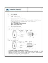
R-Net™ Omni Setup 11.1
Navigation
Up & Down button to
navigate the menus,
Right button to open a
menu item and Left but-
ton to return to previous
menu.
Plus & Minus
Toggle settings or changes
value of the highlighted
parameter.
Power
Turns chair ON/OFF.
Profile
Switch between
preset drive pro-
files and activate
device as control.
Mode
Switch mode to
drive, power seating,
or OBP (onboard
programming)
R-Net™ Programming Dongle

10
R-Net™ Setup 11.0
1. Plug in the R-Net™ Programming Dongle in line with the Omni display and chair’s
electronics, and then power ON the chair.
2. Press the Mode buon unl you reach the OBP (Onboard Programming) menu. The OBP
menu will appear as an hourglass while loading.
3. With the navigaon buons, navigate to Omni Global Sleep 12V and toggle Sleep
12V to On with the Plus & Minus buons. ±
4. Navigate back to the Omni menu , then navigate to Omni Port 1 (or Port 2 if the
IDPMP-9 is in Port 2).
5. In the Port menu, toggle SID to Swi with the Plus & Minus buons. ±
6. In the Port menu, navigate to Switches.
7. In the Switch menu, toggle Switch Detect to O with the Plus & Minus buons.±
8. In the Switch menu, toggle 9 Way Detect to O with the Plus & Minus buons. ±
9. Navigate with the Le buon back to the Omni menu, and then navigate to Proled.
10. In the Proled menu, congure a prole to use the port for the i-Drive.
11. Power o the chair, remove the R-Net± Programming Dongle, reconnect the Omni Display,
and power on the chair.
The chair should now be programmed to recognize the i-Drive. Be sure to re-engage the
motors before operaon.
/