Page is loading ...

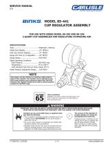
MODEL 85-441
CUP REGULATOR ASSEMBLY
FOR USE WITH BINKS MODEL 80-295 AND 80-296
2-QUART CUP ASSEMBLIES FOR REGULATING ATOMIZING AIR
WARNING
IMPORTANT: READ AND FOLLOW ALL INSTRUCTIONS AND SAFETY PRECAUTIONS BEFORE INSTALLING,
OPERATING OR MAINTAINING THIS EQUIPMENT. KEEP THIS MANUAL FOR FUTURE REFERENCE.
Improper use can cause bodily injury or equipment dam-
age. Read the following:
• This air regulator and gauge assembly is intended only for use
in general service AIR SYSTEMS. Do not use for liquids or
gases other than air.
• Do not use where pressure or temperature can exceed rated
operating conditions (see specifications).
• Regulated outlet pressure must never be set higher than the
maximum operating pressure of the downstream air tool or
equipment. An outlet pressure gauge should always be used.
The accuracy of the indication of
pressure gauges can change dur-
ing shipment and normal use.
If gauge accuracy is necessary for pre-
venting risks of injury or property dam-
age, the gauge should be checked
before use and on a routine periodic
basis. (See ANSI B40-1974 for gauge
standards.)
!
SPECIFICATIONS
Type .............................................. Diaphragm, relieving
Outlet Size (Nipple) ........................ 1/4" NPS(m)
Inlet Size (Swivel Adapter) .............. 1/4" NPS(f)
Gauge Port Size (2) in Regulator ..... 1/8" NPT(f)
Gauge Range ................................. 0-60 PSIG
Rated Operating Conditions:
Inlet Pressure ............................. 300 PSIG max.
Temperature ............................... 0º to 150º F
(with dewpoint less than air temp. below 35º F)
Outlet Pressure Adjustment Range .... 2-50 PSIG*
*
NOTE
This range is not the minimum or maximum outlet pressure
limit for this regulator. The regulator can be adjusted to zero
PSIG outlet pressure and to pressures higher than 100 PSIG.
However, this regulator should not be used to control pressures
outside this specified range.
77-2825-R3 (3/2022) 1 / 4 www.carlisleft.com
EN
SERVICE MANUAL

ITEM PART
NO. NO. DESCRIPTION
QTY.
1 ■ AIR REGULATOR ........................ 1
2 SSP-8217-ZN SWIVEL ADAPTER, 1/4 IN. ............ 1
3 85-70 GAUGE,
60 PSI ............................. 1
4 H-2008 DM NIPPLE, 1/4 NPT X 1/4 NPS ........ 1
■ KK-4887-2 DIAPHRAGM REPAIR KIT ............. –
(ORDER SEPARATELY)
PARTS LIST
When ordering, please specify Part No.
INSTALLATION
Assemble the 85-441 Regulator
to your Binks cup assembly as
shown at right.
EN
77-2825-R3 (3/2022)2 / 4www.carlisleft.com

REGULATOR OPERATION, PREVENTATIVE MAINTENANCE, CLEANING & REASSEMBLY
OPERATION
1. Before turning on system air pressure, turn adjusting
knob full counterclockwise. This will close regulator to
produce zero air pressure. The knob is locked in
position when pushed downward towards the regulator
body.
2. Turn on system air pressure.
3. Turn regulator adjusting knob clockwise until desired
outlet pressure is reached.
4. To avoid minor readjustment after making a change in
pressure setting, always approach the desired pressure
from a lower pressure. When reducing from a higher
to a lower setting, first reduce to some pressure less
than that desired, then bring up to the desired point.
Lock the pressure setting by pushing the knob
downward.
PREVENTATIVE MAINTENANCE
1. Turn regulator knob counterclockwise until it stops.
2. Unscrew the bonnet from the regulator body, remove
adjusting screw and nut, then the regulating spring,
slip ring (1) and diaphragm (2). Using a screwdriver,
unscrew the valve seat (3) and o-ring (4). Then
remove valve (5) and valve spring (6).
CLEANING
1. Clean parts using warm water and soap.
2. Inspect all parts and replace any damaged ones.
CAUTION
Do not submerge regulator in spray gun solvents or use
solvents to clean regulator parts. Damage may occur to gauge
or regulator components.
!
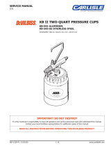
ITEM
NO. DESCRIPTION
QTY.
1 SLIP RING ....................................................... 1
2 DIAPHRAGM ..................................................... 1
3 VALVE SEAT ..................................................... 1
4 O-RING ............................................................ 1
5 VALVE, PTFE .................................................... 1
6 VALVE SPRING ................................................. 1
KK-4887-2
DIAPHRAGM REPAIR KIT
BONNET
ADJUSTING SCREW
NUT
REGULATING SPRING
REASSEMBLY
1. At reassembly, apply a small amount of lubricant (SSL-10
gun lube) to adjusting screw threads inside bonnet.
2. Torque valve seat (3) to 4-6 in.-lbs. (do not over-
tighten). Torque bonnet to 50-60 in.-lbs.
WARNING
Risk of injury from pressurized components. Turn off inlet air
pressure and bleed off remaining pressure BEFORE disassembly.
!
EN
77-2825-R3 (3/2022) 3 / 4 www.carlisleft.com

EN
77-2825-R3 (3/2022)4 / 4www.carlisleft.com
WARRANTY POLICY
This product is covered by Carlisle Fluid Technologies’ materials and workmanship limited warranty.
The use of any parts or accessories, from a source other than Carlisle Fluid Technologies,
will void all warranties. Failure to reasonably follow any maintenance guidance provided
may invalidate any warranty.
For specic warranty information please contact Carlisle Fluid Technologies.
Carlisle Fluid Technologies is a global leader in innovative nishing technologies.
Carlisle Fluid Technologies reserves the right to modify equipment specications without prior notice.
BGK™, Binks®, DeVilbiss®, Hosco®, MS®, and Ransburg®
are all registered trademarks of Carlisle Fluid Technologies, Inc.
©2022 Carlisle Fluid Technologies, Inc.
All rights reserved.
For technical assistance or to locate an authorized distributor,
contact one of our international sales and customer support locations.
Region Industrial/Automotive Automotive Renishing
Americas Tel: 1-800-992-4657 Tel: 1-800-445-3988
Fax: 1-888-246-5732 Fax: 1-800-445-6643
Europe, Africa,
Middle East, India
Tel: +44 (0)1202 571 111
Fax: +44 (0)1202 573 488
China Tel: +8621-3373 0108
Fax: +8621-3373 0308
Japan Tel: +81 45 785 6421
Fax: +81 45 785 6517
Australia Tel: +61 (0) 2 8525 7555
Fax: +61 (0) 2 8525 7575
For the latest information about our products, visit www.carlisleft.com
16430 North Scottsdale Rd., Suite 450 Scottsdale, AZ 85254 USA
/