Page is loading ...

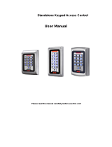
W3 seriesW1 series
W1-B/C W3-B/C
Metal Waterproof Access Control
User Manual

This is a proximity and waterproof access controller, IP65,
which is a modern and advanced access control system. It
uses the latest central processor(CPU), W1/W3-B can store
2500 users; W1/W3-C can stores 2000. It supports card, card
plus PIN and card/PIN three access modes, also can add PIN
independently. Anti-vandal, alarm, exit button, safe mode,
wiegand input/output, etc, which make the user safer.
1. Introduction
2. Technical Specifications
Features Description
Appearance Metal case, anti-explosion and anti-tamper
Waterproof
Input voltage
Capacity(max)
PIN
Master card
As reader
Connect external
reader
Connect high
power alarm
IP 65
DC: 12-24V AC: 12-18V
W1/W3-B: 2500 W1/W3-C: 2000
W1/W3-B: 4digits W1/W3-C: 4-8 digits.
Not related to the card.
Add/delete user
Support Wiegand 26bits, PIN wiegand
output is virtual number.
Can connect any EM/HID/IC readers with
wiegand 26 output
External current of the alarm ≥3A
3. Installation Procedure
3.1 Installation and Fixation
3.1.1
Drill hole on the wall according to the back size of the machine
or install distributing box well.
3.1.2
Thread the cable through cable hole, connect related cable. For
the un-used cable please separate with insulating tape and keep
well in case of short circuit.
3.1.3
Fix back cover on the wall or distributing box with screw.
3.1.4
After wiring, install front casing to the back casing and fix well. Purple
Orange
Blue
Black
Red
Brown
Yellow
Grey
White
Green
NC
COM
NO
AC&DC
AC&DC
D_IN
OPEN
ALARM-
D0
GND
D1
Pink
3.2 Wiring
Function Color Description
Wiegand 26 output/input
Wiegand 26 output/input
Alarm Negative
Request to Exit Button
Door Contact
12V AC&DC Regulated Power Input
12V AC&DC Regulated Power Input
Relay NO
Relay COM
Relay NC
W1-B/C W3-B/C Negative
1
2
3
4
5
6
7
8
9
0
#
PCB connect diagram
Anti- dem olition alarm
D0
D1
ALARM-
OPEN
D_IN
GND
AC&DC
AC&DC
NC
COM
NO
J1
D0
D1
ALA RM-
OPE N
D_I N
GND
AC& DC
AC& DC
NC
COM
NO
J1
W1-B/C W3-B/C

3.3 Connection Diagram
3.3.1 Common power supply
D0
D1
ALARM-
OPEN
D_IN
GND
W1/W3-B/C
One door Access Control
AC&DC
AC&DC
NC
COM
NO
AC&DC
1 2 V /3A
Purple
Orange
Blue
Black
Red
Brown
Yellow
Grey
White
Green
Pink Negative Output
Wiegand Output/Input
Wiegand Output/Input
Connect Alarm Negative
Exit Button
Door Contact Button
Relay NO, Normal when Circuit Open
Relay Common Port, Connect Power Supply Negative
Relay NC, Normal when Circuit Closed
Alarm
Power
Alarm Power Supply
Positive
-
+
In 40 04
Connect Power Supply Positive
Connect “NC” or “NO”
according to specific lock type
Diode white port connect positive side of the
lock, the other port connect the negative
Lock
3.3.2 Special Power Supply
D0
D1
ALARM-
OPEN
D_IN
DC12V/3A
-
+
Wiegand Output/Input
Wiegand Output/Input
GND
AC&DC
AC&DC
NC
COM
NO
NC COM NO +12V GND OPEN
Green
White
Grey
Yellow
Brown
Red
Black
Blue
Purple
Orange
Pink
Door detecting
switch
Exit Button
Alarm
Power
+
-
+
-
Fail-secure lock
Alarm“-”
Negative Output
Connect
Alarm Negative
Relay NO, Normal when Circuit Open
Relay Common Port
Relay NC, Normal when Circuit Closed
Fail-safe lock
W1/W3-B/C
One door Access Control


/