Page is loading ...

- 1 - - 3 -
- 2 - - 4 -
Model/Modèle/Modelo #:
LF1057-WH1-48LF0-G
48 in. Energy Saving Linear Ceiling Fixture
(Page 1)
Luminaire de plafond linéaire permettant de
réaliser des économies d’énergie de 122 cm
(Page 4)
Accesorio para iluminación LED de techo
decorativo lineal de 48 pulgadas
(Página 7)
To Begin/Pour commencer/Para comenzar
WARNING: Please read this entire manual before installation. Verify the following contents:
AVERTISSEMENT : Veuillez lire tout ce mode d’emploi avant l’installation. Vérifiez que tous
les éléments ci-dessous sont présents :
ADVERTENCIA: Por favor, lea este manual completo antes de realizar la instalación.
Verifique el siguiente contenido:
Fixture Pan
Panneau de fixation du luminaire
Bandeja del accesorio
para iluminación
Diffuser
Diffuseur
Difusor
ReadyAnchor™
Required/Nécessaire/Se necesita
Installation time: 30 minutes/Durée de l’installation: 30 minutes/Tiempo de instalación: 30 minutos
Safety glasses
Lunettes de sécurité
Anteojos de seguridad
Flathead screwdriver
Tournevis à tête plate
Destornillador de cabeza plana
Step ladder
Escabeau
Escalera de mano
Phillips screwdriver
Tournevis à pointe cruciforme
Destornillador Phillips
Pliers
Pince
Alicates
Hardware kit*
Kit de petit matériel de fixation*
Kit de herrajes*
Mounting bracket
Fentes en forme de trou de serrure
Soporte de montaje
Support chain
Chaîne de support
Cadena de soporte
* Actual hardware may differ from illustration
* Les éléments de fixation réels peuvent être
différents de ceux de l’illustration.
* Los herrajes reales pueden diferir de los que
se muestran en la ilustración
Important Safety Instructions
Installation
Disconnect power to the electrical box and remove the old fixture. If more than two
wire leads are present, keep track of which wires were connected together.
5
6
WARNING: To reduce the risk of FIRE, ELECTRIC SHOCK, OR INJURY TO
PERSONS:
1. For INDOOR USE ONLY.
2. Do NOT touch LEDs.
3. Do NOT look directly at lighted LEDs for any length of time.
4. Do NOT touch, operate, or install fixture while in contact with water.
5. Not intended for illumination of aquariums.
6. Electrical requirements for LF1057-WH1-48LFO-G:
120~277VAC, 50/60HZ 0.56A/0.26A
7. Do not leave bare wires exposed outside of the electrical box.
SAVE THESE INSTRUCTIONS IN A LOCATION CLOSE TO THE FIXTURE TO
REFER TO THEM AT A LATER TIME.
Installation
Care and Maintenance
Minor problems often can be fixed without the help of an electrician. Before doing any work
on the fixture, shut off power supply at the circuit breaker panel to avoid electrical shock.
Problem Cause Solution
Fixture doesn’t light. Power is off. Check if power supply is on.
Bad connection. Check cords and/or wiring.
Bad switch. Test or replace switch.
Fuse blows or circuit breaker Discontinue use. Call customer service.
trips when light is turned on.
Troubleshooting Guide
8
9
IMPORTANT: This fixture uses LEDs (light emitting diodes) to provide light. LEDs do not
burn out like traditional light bulbs and will last for 50 years or more (based on 3 hours of
usage per day).
Periodically clean the fixture and diffuser using a mild, non-abrasive cleaner and soft
cloth. When cleaning the fixture, make sure the power is turned off. Do not spray cleaner
directly onto any part of the fixture or LEDs.
10
In the event you are missing a part or have questions regarding installation
please visit our website at www.goodearthlighting.com/support or
call the Customer Care Center 1-800-291-8838,
8:30 a.m.-5 p.m., CST, Monday-Friday.
Need Help?
Good Earth Lighting
®
Warranty
Printed in China
10 YEAR LIMITED WARRANTY
The manufacturer warrants this lighting fixture to be free from defects in materials and
workmanship for a period of (10) years from the date of original purchase by the
consumer. The fixture is not warrantied for use in a commercial or retail application.
The warranty is limited to use in a residential environment. We will repair or replace (at
our option) the unit in the original color and style if available, or in a similar color and
style if the original item has been discontinued, without charge. Defective units must be
properly packed and returned to the manufacturer with a letter of explanation and your
original purchase receipt showing date of purchase. Call 1-800-291-8838 to obtain a
return authorization number and an address where to ship your defective product.
Note: C.O.D. shipments will NOT be accepted. The liability of the manufacturer is in any
case limited to replacement of the defective light fixture product. The manufacturer will
not be liable for any other loss, damage, labor costs or injury which is caused by the
product. This limitation upon the liability of the manufacturer includes any loss,
damage, labor costs or injury which is (I) to person or property or otherwise; (II)
incidental or consequential in nature; (III) based upon theories of warranty, contract,
negligence, strict liability, tort, or otherwise; or (IV) directly, or indirectly related to the
sale, use, or repair of the product. This warranty gives you specific rights, and you may
also have other rights which vary from state to state.
Good Earth Lighting® 1400 East Business Center Drive, Ste. 108
Mount Prospect, IL 60056
Good Earth Lighting® is a registered trademark of Good Earth Lighting, Inc.
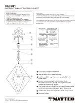
Pull the fixture wires through the hole in the center of
the fixture pan to the backside of the fixture. Using
the support chain, connect one end to the back of
the fixture pan near the center in the specially
designed slots (Fig. 6) Hook the other end of the
support chain to the electrical box (Fig. 7). This
will allow for a hands free support for wiring.
Fig. 8
For safety and proper operation, the fixture must be
properly grounded. A green or bare copper ground
wire is preattached to the fixture pan. The fixture
ground wire must be spliced to the green or bare
copper ground wire in the electrical box using
one of the wire nuts (Fig. 8). If house wiring does
not include a ground wire, consult local
electrical code for approved grounding methods.
Insert the diffuser into the fixture pan (Fig. 18). While
holding on to the diffuser, rotate all four hinges
counter-clockwise to lock the diffuser in
place (Fig. 19).
7
Fig. 9
Fig. 10
Connect the supply leads from the electrical box
to the fixture wire leads using the pre-installed
push-in connectors as per the illustration
(Fig. 9). Insert the black supply lead into the
open hole in the push-in connector with the
black fixture wires already inserted into it.
Insert the white supply lead into the open hole
in the push-in connector with the white fixture
wires already inserted into it (Fig. 10). All wire
connections should be made on the backside of the fixture. Carefully push the excess
wires back inside the electrical box.
Fig. 11
1
Fig. 12
1
Fig. 13
2
2
Fig. 6
Fig. 18
Position the fixture pan over the long machine screws
attached to the mounting bracket, insert the
screwheads into the keyhole slots by engaging the
straight keyhole slot over the first screwhead. Use
this as a pivot point and maneuver the curved keyhole
slot over the second screwhead (Fig. 11).
Maneuver the fixture until both screwheads are
engaged in the narrow channels of both keyhole slots.
Once the mounting screws are engaged, maneuver the
fixture until the desired positioning of the fixture has
been achieved (Fig. 12). Fully tighten the mounting
screws (Fig. 13). NOTE: Fixture MUST be properly
secured to the electrical box first. The primary fixture
support is ALWAYS the electrical box.
1
2
If either ReadyAnchor™ (patent pending) has come off during
shipping, re-insert the ReadyAnchor back into its mounting hole
(Fig. 14). Each mounting hole has 2 nibs located opposite each
other. The ReadyAnchor is held into place by locking tabs that lock
it to the fixture and they must be positioned so the nibs correspond
with the gaps between the locking tabs.
If extra support is required, in a typical drywall installation, use the
pre-attached ReadyAnchor to further secure the outer ends of the
fixture. Once the ReadyAnchor is in place, use
a hand held phillips head screwdriver, and
apply upward pressure on the ReadyAnchor
to cause it to break free of the base ring, and
puncture into the drywall (Fig. 15). It is NOT
recommended to use a powered drill to
secure the ReadyAnchor (Fig. 16). Continue to
screw in the ReadyAnchor until the top is fully
seated onto the remaining base ring still
attached to the fixture (Fig. 17). Do not OVERTIGHTEN, as this may strip out the drywall.
If the anchor hits a wooden ceiling joist, insert one of the included wood screws into the
center hole of the ReadyAnchor and drive it in. DO NOT ovetighten. NOTE: The screws
only need to be used if a wood joist is encountered during installation.
Fig. 14
Fig. 15 Fig. 16
Fig. 17
3
2
1
4
Prepare the mounting bracket by attaching both long
machine screws into two opposite round threaded holes
on the mounting bracket (Fig. 1). If the mounting bracket
has more than 2 threaded holes,
measure the distance between
the keyhole slots in the fixture
pan (Fig. 2) and match them up
to the corresponding threaded
holes in the mounting bracket. Attach the screws to the
mounting bracket until they are against the mounting bracket.
If the keyhole slots are not punched through, remove
the appropriate knockouts from the back side of the
fixture pan that correspond to the positions of the
mounting screw heads on the mounting bracket (Fig. 5).
This can be done using a flathead screwdriver and
pliers.
Unscrew both long machine screws until the heads of
the screws extend about a 3/8 in. below the ceiling
surface (Fig. 4). NOTE: For proper installation, the
machine screws should be perpendicular to the floor.
Remove the existing screws from the electrical box.
Pull the supply wires from the electrical box through
the center hole of the mounting bracket. Attach the
mounting bracket to the electrical box, using the
electrical box screws removed earlier. Both long
machine screws installed in Step 1 should be
oriented with both screwheads facing toward the
floor and they be aligned with the center run of the
fixture position
(Fig. 3).
Fig. 1
Fig. 4
Fig. 3
Fig. 5
1
2
Fig. 2
Fig. 19
Dimmer Instructions
This fixture is not intended to be used with dimmers, motion sensors, light sensors,
timers or any other external controls.
Fig. 7
English
Warnings and Cautions
WARNING
• Shut off power at the circuit breaker or fuse panel before removing the
old fixture or installing the new one.
• LEDs can be damaged by electrostatic discharge (ESD) shock. Before
installation, discharge yourself by touching a grounded bare metal
surface to remove this hazard. To avoid damage, do not remove the
clear lens over the LED module.
CAUTION
• This device complies with Part 15 of the FCC rules. Operation is subject
to the following two conditions: (1) This device may not cause harmful
interference, and (2) this device must accept any interference received,
including interference that may cause undesired operation.

- 1 - - 3 -
- 2 - - 4 -
Model/Modèle/Modelo #:
LF1057-WH1-48LF0-G
48 in. Energy Saving Linear Ceiling Fixture
(Page 1)
Luminaire de plafond linéaire permettant de
réaliser des économies d’énergie de 122 cm
(Page 4)
Accesorio para iluminación LED de techo
decorativo lineal de 48 pulgadas
(Página 7)
To Begin/Pour commencer/Para comenzar
WARNING: Please read this entire manual before installation. Verify the following contents:
AVERTISSEMENT : Veuillez lire tout ce mode d’emploi avant l’installation. Vérifiez que tous
les éléments ci-dessous sont présents :
ADVERTENCIA: Por favor, lea este manual completo antes de realizar la instalación.
Verifique el siguiente contenido:
Fixture Pan
Panneau de fixation du luminaire
Bandeja del accesorio
para iluminación
Diffuser
Diffuseur
Difusor
ReadyAnchor™
Required/Nécessaire/Se necesita
Installation time: 30 minutes/Durée de l’installation: 30 minutes/Tiempo de instalación: 30 minutos
Safety glasses
Lunettes de sécurité
Anteojos de seguridad
Flathead screwdriver
Tournevis à tête plate
Destornillador de cabeza plana
Step ladder
Escabeau
Escalera de mano
Phillips screwdriver
Tournevis à pointe cruciforme
Destornillador Phillips
Pliers
Pince
Alicates
Hardware kit*
Kit de petit matériel de fixation*
Kit de herrajes*
Mounting bracket
Fentes en forme de trou de serrure
Soporte de montaje
Support chain
Chaîne de support
Cadena de soporte
* Actual hardware may differ from illustration
* Les éléments de fixation réels peuvent être
différents de ceux de l’illustration.
* Los herrajes reales pueden diferir de los que
se muestran en la ilustración
Important Safety Instructions
Installation
Disconnect power to the electrical box and remove the old fixture. If more than two
wire leads are present, keep track of which wires were connected together.
5
6
WARNING: To reduce the risk of FIRE, ELECTRIC SHOCK, OR INJURY TO
PERSONS:
1. For INDOOR USE ONLY.
2. Do NOT touch LEDs.
3. Do NOT look directly at lighted LEDs for any length of time.
4. Do NOT touch, operate, or install fixture while in contact with water.
5. Not intended for illumination of aquariums.
6. Electrical requirements for LF1057-WH1-48LFO-G:
120~277VAC, 50/60HZ 0.56A/0.26A
7. Do not leave bare wires exposed outside of the electrical box.
SAVE THESE INSTRUCTIONS IN A LOCATION CLOSE TO THE FIXTURE TO
REFER TO THEM AT A LATER TIME.
Installation
Care and Maintenance
Minor problems often can be fixed without the help of an electrician. Before doing any work
on the fixture, shut off power supply at the circuit breaker panel to avoid electrical shock.
Problem Cause Solution
Fixture doesn’t light. Power is off. Check if power supply is on.
Bad connection. Check cords and/or wiring.
Bad switch. Test or replace switch.
Fuse blows or circuit breaker Discontinue use. Call customer service.
trips when light is turned on.
Troubleshooting Guide
8
9
IMPORTANT: This fixture uses LEDs (light emitting diodes) to provide light. LEDs do not
burn out like traditional light bulbs and will last for 50 years or more (based on 3 hours of
usage per day).
Periodically clean the fixture and diffuser using a mild, non-abrasive cleaner and soft
cloth. When cleaning the fixture, make sure the power is turned off. Do not spray cleaner
directly onto any part of the fixture or LEDs.
10
In the event you are missing a part or have questions regarding installation
please visit our website at www.goodearthlighting.com/support or
call the Customer Care Center 1-800-291-8838,
8:30 a.m.-5 p.m., CST, Monday-Friday.
Need Help?
Good Earth Lighting
®
Warranty
Printed in China
10 YEAR LIMITED WARRANTY
The manufacturer warrants this lighting fixture to be free from defects in materials and
workmanship for a period of (10) years from the date of original purchase by the
consumer. The fixture is not warrantied for use in a commercial or retail application.
The warranty is limited to use in a residential environment. We will repair or replace (at
our option) the unit in the original color and style if available, or in a similar color and
style if the original item has been discontinued, without charge. Defective units must be
properly packed and returned to the manufacturer with a letter of explanation and your
original purchase receipt showing date of purchase. Call 1-800-291-8838 to obtain a
return authorization number and an address where to ship your defective product.
Note: C.O.D. shipments will NOT be accepted. The liability of the manufacturer is in any
case limited to replacement of the defective light fixture product. The manufacturer will
not be liable for any other loss, damage, labor costs or injury which is caused by the
product. This limitation upon the liability of the manufacturer includes any loss,
damage, labor costs or injury which is (I) to person or property or otherwise; (II)
incidental or consequential in nature; (III) based upon theories of warranty, contract,
negligence, strict liability, tort, or otherwise; or (IV) directly, or indirectly related to the
sale, use, or repair of the product. This warranty gives you specific rights, and you may
also have other rights which vary from state to state.
Good Earth Lighting® 1400 East Business Center Drive, Ste. 108
Mount Prospect, IL 60056
Good Earth Lighting® is a registered trademark of Good Earth Lighting, Inc.
Pull the fixture wires through the hole in the center of
the fixture pan to the backside of the fixture. Using
the support chain, connect one end to the back of
the fixture pan near the center in the specially
designed slots (Fig. 6) Hook the other end of the
support chain to the electrical box (Fig. 7). This
will allow for a hands free support for wiring.
Fig. 8
For safety and proper operation, the fixture must be
properly grounded. A green or bare copper ground
wire is preattached to the fixture pan. The fixture
ground wire must be spliced to the green or bare
copper ground wire in the electrical box using
one of the wire nuts (Fig. 8). If house wiring does
not include a ground wire, consult local
electrical code for approved grounding methods.
Insert the diffuser into the fixture pan (Fig. 18). While
holding on to the diffuser, rotate all four hinges
counter-clockwise to lock the diffuser in
place (Fig. 19).
7
Fig. 9
Fig. 10
Connect the supply leads from the electrical box
to the fixture wire leads using the pre-installed
push-in connectors as per the illustration
(Fig. 9). Insert the black supply lead into the
open hole in the push-in connector with the
black fixture wires already inserted into it.
Insert the white supply lead into the open hole
in the push-in connector with the white fixture
wires already inserted into it (Fig. 10). All wire
connections should be made on the backside of the fixture. Carefully push the excess
wires back inside the electrical box.
Fig. 11
1
Fig. 12
1
Fig. 13
2
2
Fig. 6
Fig. 18
Position the fixture pan over the long machine screws
attached to the mounting bracket, insert the
screwheads into the keyhole slots by engaging the
straight keyhole slot over the first screwhead. Use
this as a pivot point and maneuver the curved keyhole
slot over the second screwhead (Fig. 11).
Maneuver the fixture until both screwheads are
engaged in the narrow channels of both keyhole slots.
Once the mounting screws are engaged, maneuver the
fixture until the desired positioning of the fixture has
been achieved (Fig. 12). Fully tighten the mounting
screws (Fig. 13). NOTE: Fixture MUST be properly
secured to the electrical box first. The primary fixture
support is ALWAYS the electrical box.
1
2
If either ReadyAnchor™ (patent pending) has come off during
shipping, re-insert the ReadyAnchor back into its mounting hole
(Fig. 14). Each mounting hole has 2 nibs located opposite each
other. The ReadyAnchor is held into place by locking tabs that lock
it to the fixture and they must be positioned so the nibs correspond
with the gaps between the locking tabs.
If extra support is required, in a typical drywall installation, use the
pre-attached ReadyAnchor to further secure the outer ends of the
fixture. Once the ReadyAnchor is in place, use
a hand held phillips head screwdriver, and
apply upward pressure on the ReadyAnchor
to cause it to break free of the base ring, and
puncture into the drywall (Fig. 15). It is NOT
recommended to use a powered drill to
secure the ReadyAnchor (Fig. 16). Continue to
screw in the ReadyAnchor until the top is fully
seated onto the remaining base ring still
attached to the fixture (Fig. 17). Do not OVERTIGHTEN, as this may strip out the drywall.
If the anchor hits a wooden ceiling joist, insert one of the included wood screws into the
center hole of the ReadyAnchor and drive it in. DO NOT ovetighten. NOTE: The screws
only need to be used if a wood joist is encountered during installation.
Fig. 14
Fig. 15 Fig. 16
Fig. 17
3
2
1
4
Prepare the mounting bracket by attaching both long
machine screws into two opposite round threaded holes
on the mounting bracket (Fig. 1). If the mounting bracket
has more than 2 threaded holes,
measure the distance between
the keyhole slots in the fixture
pan (Fig. 2) and match them up
to the corresponding threaded
holes in the mounting bracket. Attach the screws to the
mounting bracket until they are against the mounting bracket.
If the keyhole slots are not punched through, remove
the appropriate knockouts from the back side of the
fixture pan that correspond to the positions of the
mounting screw heads on the mounting bracket (Fig. 5).
This can be done using a flathead screwdriver and
pliers.
Unscrew both long machine screws until the heads of
the screws extend about a 3/8 in. below the ceiling
surface (Fig. 4). NOTE: For proper installation, the
machine screws should be perpendicular to the floor.
Remove the existing screws from the electrical box.
Pull the supply wires from the electrical box through
the center hole of the mounting bracket. Attach the
mounting bracket to the electrical box, using the
electrical box screws removed earlier. Both long
machine screws installed in Step 1 should be
oriented with both screwheads facing toward the
floor and they be aligned with the center run of the
fixture position
(Fig. 3).
Fig. 1
Fig. 4
Fig. 3
Fig. 5
1
2
Fig. 2
Fig. 19
Dimmer Instructions
This fixture is not intended to be used with dimmers, motion sensors, light sensors,
timers or any other external controls.
Fig. 7
English
Warnings and Cautions
WARNING
• Shut off power at the circuit breaker or fuse panel before removing the
old fixture or installing the new one.
• LEDs can be damaged by electrostatic discharge (ESD) shock. Before
installation, discharge yourself by touching a grounded bare metal
surface to remove this hazard. To avoid damage, do not remove the
clear lens over the LED module.
CAUTION
• This device complies with Part 15 of the FCC rules. Operation is subject
to the following two conditions: (1) This device may not cause harmful
interference, and (2) this device must accept any interference received,
including interference that may cause undesired operation.
/