
ME03-PE0
AMD EPYC™ 8004 UP Server Board
User Manual
Rev. 1.0

Copyright
© 2023 GIGA-BYTE TECHNOLOGY CO., LTD. All rights reserved.
The trademarks mentioned in this manual are legally registered to their respective owners.
Disclaimer
Information in this manual is protected by copyright laws and is the property of GIGABYTE.
Changes to the specifications and features in this manual may be made by GIGABYTE
without prior notice. No part of this manual may be reproduced, copied, translated, transmitted, or
published in any form or by any means without GIGABYTE's prior written permission.
Documentation Classications
In order to assist in the use of this product, GIGABYTE provides the following types of documentation:
UserManual:detailedinformation&stepsabouttheinstallation,congurationandusethis
product (e.g. motherboard, server barebones), covering hardware and BIOS.
User Guide: detailed information about the installation & use of an add-on hardware or
softwarecomponent(e.g.BMCrmware,rail-kit)compatiblewiththisproduct.
Quick Installation Guide: a short guide with visual diagrams that you can reference easily for
installation purposes of this product (e.g. motherboard, server barebones).
Please see the support section of the online product page to check the current availability of these
documents
For More Information
Forrelatedproductspecications,thelatestrmwareandsoftware,andotherinformation,pleasevisit
our website at: http://www.gigabyte.com.
For GIGABYTE distributors and resellers, additional sales & marketing materials are available from our
reseller portal: http://reseller.b2b.gigabyte.com
For further technical assistance, please contact your GIGABYTE representative or visit
http://esupport.gigabyte.com/ to create a new support ticket.
For any general sales or marketing enquires, you may message GIGABYTE server directly by
email: server[email protected].

- 3 -
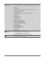
Table of Contents
ME03-PE0 Motherboard Layout ......................................................................................5
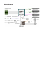
Block Diagram .................................................................................................................7
Chapter 1 Hardware Installation .....................................................................................8
1-1 Installation Precautions .................................................................................... 8
1-2 ProductSpecications ...................................................................................... 9
1-3 Installing and Removing the CPU and Heat Sink ........................................... 12
1-4 Installing and Removing Memory ................................................................... 13
1-4-1 6-ChannelMemoryConguration ..........................................................................13
1-4-2 Installing and Removing the Memory Module .......................................................14
1-4-3 Processor and Memory Module Matrix Table .........................................................14
1-4-4 Memory Population Table ......................................................................................15
1-5 Installing the M.2 SSD Module ....................................................................... 16
1-6 Back Panel Connectors .................................................................................. 17
1-7 Internal Connectors ........................................................................................ 18
1-8 Jumper Settings ............................................................................................. 26
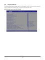
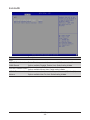
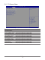
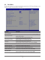
Chapter 2 BIOS Setup ..................................................................................................27
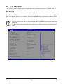
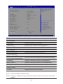
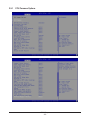
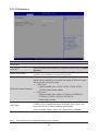
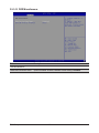
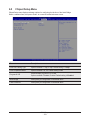
2-1 The Main Menu .............................................................................................. 29
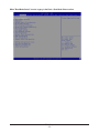
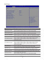
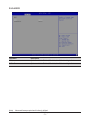
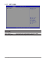
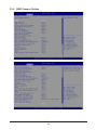
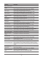
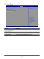
2-2 Advanced Menu ............................................................................................. 32
2-2-1 Trusted Computing .................................................................................................34
2-2-2 PSP Firmware Versions ..........................................................................................35
2-2-3 Legacy Video Select ...............................................................................................36
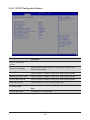
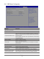
2-2-4 AST2600SuperIOConguration ...........................................................................37
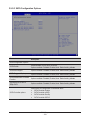
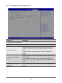
2-2-5 S5 RTC Wake Settings ...........................................................................................39
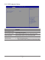
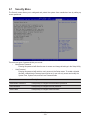
2-2-6 UEFI Settings .........................................................................................................40
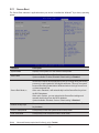
2-2-7 Serial Port Console Redirection .............................................................................41
2-2-8 CPUConguration ..................................................................................................45
2-2-9 SIO .........................................................................................................................46
2-2-10 PCI Subsystem Settings .........................................................................................47
2-2-11 USBConguration ..................................................................................................49
2-2-12 NetworkStackConguration ..................................................................................51
2-2-13 NVMeConguration ...............................................................................................52
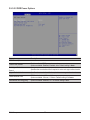
2-2-14 SATAConguration.................................................................................................53
2-2-15 GraphicOutputConguration .................................................................................54
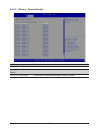
2-2-16 AMDMemCongurationStatus .............................................................................55
2-2-17 TlsAuthConguration ............................................................................................56
2-2-18 RAMDiskConguration .........................................................................................57

- 4 -
2-2-19 iSCSIConguration ................................................................................................58
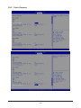
2-3 AMD CBS Menu ............................................................................................. 59
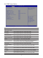
2-3-1 CPU Common Options ...........................................................................................60
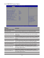
2-3-2 DF Common Options ..............................................................................................66
2-3-3 UMC Common Options ..........................................................................................73
2-3-4 NBIO Common Options ..........................................................................................94
2-3-5 FCH Common Options .........................................................................................104
2-3-6 Soc Miscellaneous Control ...................................................................................113
2-3-7 Workload Tuning ................................................................................................... 115
2-3-8 CXL Common Options .......................................................................................... 116
2-4 AMD PBS Menu ........................................................................................... 117
2-4-1 RAS ......................................................................................................................118
2-5 Chipset Setup Menu ..................................................................................... 120
2-5-1 North Bridge .........................................................................................................121
2-5-2 Fabric Resource ...................................................................................................122
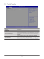
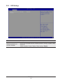
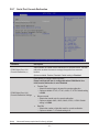
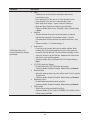
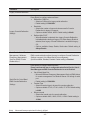
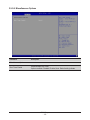
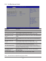
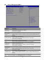
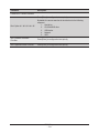
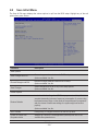
2-6 Server Management Menu ........................................................................... 124
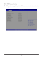
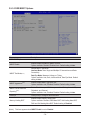
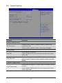
2-6-1 System Event Log ................................................................................................126
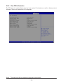
2-6-2 View FRU Information ..........................................................................................127
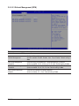
2-6-3 BMCNetworkConguration .................................................................................128
2-6-4 IPv6BMCNetworkConguration .........................................................................129
2-7 Security Menu .............................................................................................. 130
2-7-1 Secure Boot .........................................................................................................131
2-8 Boot Menu .................................................................................................... 133
2-9 Save & Exit Menu ......................................................................................... 135
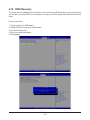
2-10 BIOS Recovery ............................................................................................ 136
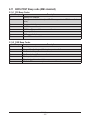
2-11 BIOS POST Beep code (AMI standard) ....................................................... 137
2-11-1 PEI Beep Codes ...................................................................................................137
2-11-2 DXE Beep Codes .................................................................................................137

- 5 -
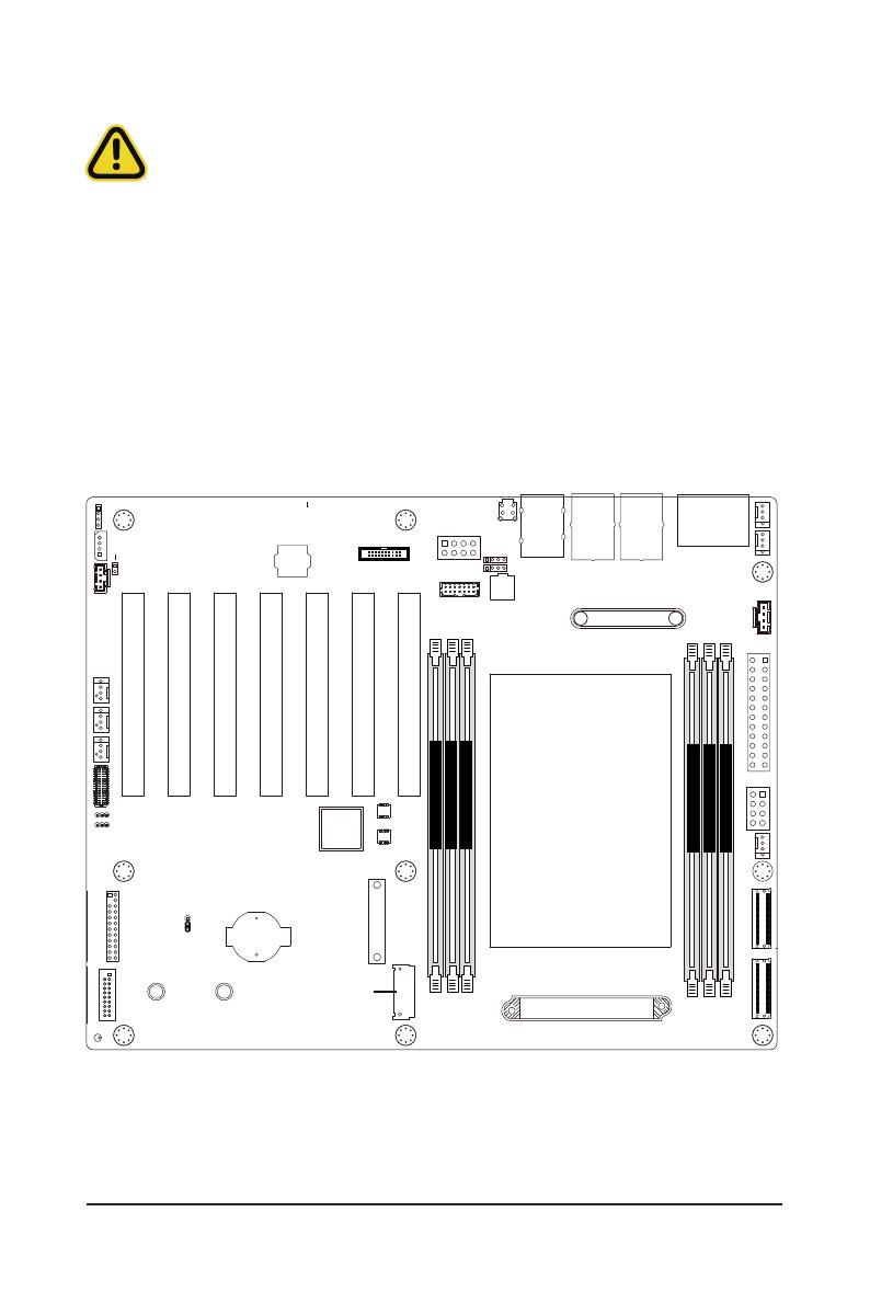
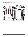
ME03-PE0 Motherboard Layout
5 64321
7
8
9
10
11
12
17 15
16 13
14
20
21
22 23
24 28
27
26
25 29
338
31
30
18
19
34
CPU0
DIMM_P0_B0
DIMM_P0_D0
DIMM_P0_A0
DIMM_P0_E0
DIMM_P0_H0
DIMM_P0_F0
32

- 6 -
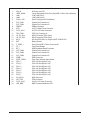
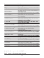
Item Code Description
1 SW_ID ID Button with LED
2 USB3_MLAN Sever Management LAN Port (Top)/USB 3.2 Gen1 Ports (Bottom)
3 LAN1 1GbE LAN Port #1
4 LAN2 1GbE LAN Port #2
5 COM1_VGA Serial Port(Top)/VGA Port(Bottom)
6 SYS_FAN1 System Fan Connector #1
7 SYS_FAN3 System Fan Connector #3
8 PMBUS PMBus Connector
9 ATX1 2x12 Pin Main Power Connector
10 P12V_AUX1 2x4 Pin 12V Power Connector
11 CPU_FAN1 CPU Fan Connector #1
12 U2_P0_G3A MCIO Connector (PCIe Gen4)
13 U2_P0_G3B MCIO Connector (PCIe Gen4)
14 M2_0 M.2 Slot(PCIe Gen4 x4, Support NGFF-2280/22110)
15 BAT Battery Socket
16 F_USB3_1 Front Panel USB 3.2 Gen1 Connector #1
17 FP_1 Front Panel Header
18 BP_1 HDD Backplane Board Connector
19 SYS_FAN4 System Fan Connector #4
20 SYS_FAN5 System Fan Connector #5
21 SYS_FAN2 System Fan Connector #2
22 IPMB1 IPMB Connector
23 CASE_OPEN1 Case Open Intrusion Alert Header
24 PCIe_1 PCIe x16 Slot #1(Gen5 x16)
25 PCIe_2 PCIe x16 Slot #2(Gen5 x16)
26 PCIe_3 PCIe x16 Slot #3(Gen5 x16)
27 PCIe_4 PCIe x16 Slot #4(Gen5 x16)
28 PCIe_5 PCIe x16 Slot #5(Gen5 x16)
29 PCIe_6 PCIe x16 Slot #6(Gen5 x16)
30 PCIe_7 PCIe x16 Slot #7(Gen5 x16)
31 CN_NCSI1 NCSI Connector
32 SPI_TPM TPM Connector
33 P12V_AUX2 2x4 Pin 12V Power Connector
34 LED_BMC BMC Firmware Readiness LED
- 7 -
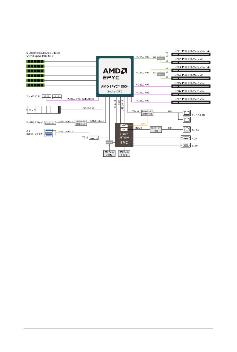
Block Diagram

- 8 -
Hardware Installation
1-1 Installation Precautions
The motherboard contains numerous delicate electronic circuits and components which can
become damaged as a result of electrostatic discharge (ESD). Prior to installation, carefully read
the user's manual and follow these procedures:
• Prior to installation, do not remove or break motherboard S/N (Serial Number) sticker or
warranty sticker provided by your dealer. These stickers are required for warranty validation.
• Always remove the AC power by unplugging the power cord from the power outlet before
installing or removing the motherboard or other hardware components.
• When connecting hardware components to the internal connectors on the motherboard,
make sure they are connected tightly and securely.
• When handling the motherboard, avoid touching any metal leads or connectors.
• It is best to wear an electrostatic discharge (ESD) wrist strap when handling electronic
components such as a motherboard, CPU or memory. If you do not have an ESD wrist
strap,keepyourhandsdryandrsttouchametalobjecttoeliminatestaticelectricity.
•
Prior to installing the motherboard, please have it on top of an antistatic pad or within an
electrostatic shielding container.
• Before unplugging the power supply cable from the motherboard, make sure the power
supply has been turned off.
• Before turning on the power, make sure the power supply voltage has been set according to
the local voltage standard.
• Before using the product, please verify that all cables and power connectors of your
hardware components are connected.
• To prevent damage to the motherboard, do not allow screws to come in contact with the
motherboard circuit or its components.
• Make sure there are no leftover screws or metal components placed on the motherboard or
within the computer casing.
• Do not place the computer system on an uneven surface
.
• Do not place the computer system in a high-temperature environment.
• Turning on the computer power during the installation process can lead to damage to
system components as well as physical harm to the user.
• If you are uncertain about any installation steps or have a problem related to the use of the
product,pleaseconsultacertiedcomputertechnician.
Chapter 1 Hardware Installation
- 9 -
Hardware Installation
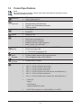
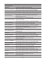
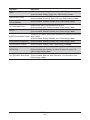
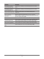
1-2 Product Specications
NOTE:
We reserve the right to make any changes to the product specications and product-related
information without prior notice.
Socket
Security
Board Size ATX
304.8 x 254mm (W x D)
Socket
Security
Processor
Supported
AMD EPYC™ 8004 Series processors
Single processor, 5nm technology
Up to 64-core, 128 threads per processor
cTDP up to 225W
Socket
Security
Socket 1 x LGA 4844
Socket SP6
Socket
Security
Chipset System on Chip
Socket
Security
Memory 6 x DIMM slots
DDR5 memory supported only
6-Channel memory architecture
RDIMM modules up to 96GB supported
Memory speed: Up to 4800 MHz
Socket
Security
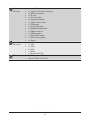
Intergrated
Network
2 x 1Gb/s BASE-T LAN ports (1 x Broadcom® BCM5720)
NCSI function supported
1 x 10/100/1000 management LAN
Socket
Security
Intergrated
Video
Controller
Integrated in Aspeed® AST2600
2D Video Graphic Adapter with PCIe bus interface
1920x1200@60Hz 32bpp, DDR4 SDRAM
Socket
Security
Integrated SATA
Controller 2 x MCIO 8i for 16 x SATA
Socket
Security
Expansion Slots Slot_7: 1 x PCIe x16 (Gen5 x16 bus) slot
Slot_6: 1 x PCIe x16 (Gen5 x16 bus) slot
Slot_5: 1 x PCIe x16 (Gen5 x16 bus) slot
Slot_4: 1 x PCIe x16 (Gen4 x8 bus) slot
Slot_3: 1 x PCIe x16 (Gen4 x16 or x8 bus) slot, shared with Slot_4
Slot_2: 1 x PCIe x16 (Gen4 x8 bus) slot
Slot_1: 1 x PCIe x16 (Gen4 x16 or x8 bus) slot, shared with Slot_2
1 x M.2 slot:
- M-key
- PCIe Gen3 x4
- Supports 2280/22110 cards
2 x MCIO 8i connectors for 4 x Gen5 NVMe or 16 x SATA
- 10 -
Hardware Installation
Socket
Security
On-Board
Connector
1 x 24-pin ATX main power connector
2 x 8-pin ATX 12V power connectors
2 x MCIO 8i connectors
1 x M.2 slot
1 x CPU fan header
5 x System fan headers
1 x USB 3.2 Gen1 header
1 x TPM header
1 x Front panel header
1 x Backplane board header
1 x PMBus connector
1 x IPMB connector
1xClearCMOSjumper
1xBIOSrecoveryjumper
1 x Buzzer
Socket
Security
Rear I/O
Connectors
2 x USB 3.2 Gen1
1 x VGA
1 x COM
2 x RJ45
1 x MLAN
1 x ID button with LED
Socket
Security
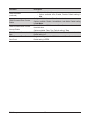
TPM 1 x TPM header with SPI interface
Optional TPM2.0 kit: CTM010
- 11 -
Hardware Installation
Socket
Security
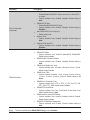
Board
Management
Aspeed® AST2600 management controller
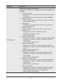
GIGABYTE Management Console (AMI MegaRAC SP-X) web interface
Dashboard
HTML5 KVM
Sensor Monitor (Voltage, RPM, Temperature, CPU Status …etc.)
Sensor Reading History Data
FRU Information
SEL Log in Linear Storage / Circular Storage Policy
Hardware Inventory
FanProle
System Firewall
Power Consumption
Power Control
Advanced power capping
LDAP / AD / RADIUS Support
Backup&RestoreConguration
Remote BIOS/BMC/CPLD Update
Event Log Filter
User Management
Media Redirection Settings
PAM Order Settings
SSL Settings
SMTP Settings
Socket
Security
Operating
Properties
Operating temperature: 10°C to 40°C
Operating humidity: 8-80% (non-condensing)
Non-operating temperature: -40°C to 60°C
Non-operating humidity: 20%-95% (non-condensing)
Socket
Security
PSU Connectors 1 x 24-pin ATX main power connector
2 x 8-pin ATX 12V power connectors

- 12 -
Hardware Installation
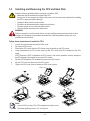
1-3 Installing and Removing the CPU and Heat Sink
Follow these instructions to Install the CPU:
1. Loosen the captive screw securing the CPU cover.
2. Flip open the CPU cover.
3. Remove the CPU carrier from the CPU frame using the handle on the CPU carrier.
4. Using the handle on the CPU carrier insert the new CPU carrier with CPU installed into the CPU
frame.
NOTE: Ensure the CPU is installed in the CPU carrier in the correct orientation, with the triangle on
the CPU aligned to the top left corner of the CPU carrier.
5. Flip the CPU frame with CPU installed into place in the CPU socket.
6. Flip the CPU cover into place over the CPU socket.
7. Tighten the CPU cover screw to secure the CPU cover in place.
Read the following guidelines before you begin to install the CPU:
• Make sure that the motherboard supports the CPU.
• Always turn off the computer and unplug the power cord from the power outlet before installing
the CPU to prevent hardware damage.
• Unplug all cables from the power outlets.
• Disconnect all telecommunication cables from their ports.
• Placethesystemunitonaatandstablesurface.
• Open the system according to the instructions.
WARNING!
Failure to properly turn off the server before you start installing components may cause serious
damage. Do not attempt the procedures described in the following sections unless you are a
qualiedservicetechnician.
Note:
• Lock the CPU by using a Torx T20 screwdriver to tighten screw.
• The screw tightening torque: 13.5 ± 0.5 kgf-cm.
1
External cap
2
3
CPU
4
5
67
8
3
1
2
4
5
6
- 13 -
Hardware Installation
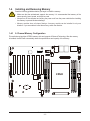
1-4 Installing and Removing Memory
Read the following guidelines before you begin to install the memory:
• Make sure that the motherboard supports the memory. It is recommended that memory of the
same capacity, brand, speed, and chips be used.
• Always turn off the computer and unplug the power cord from the power outlet before installing
the memory to prevent hardware damage.
• Memory modules have a foolproof design. A memory module can be installed in only one
direction. If you are unable to insert the memory, switch the direction.
1-4-1 6-Channel Memory Conguration
This motherboard provides 6 DDR5 memory slots and supports 6-Channel Technology. After the memory
isinstalled,theBIOSwillautomaticallydetectthespecicationsandcapacityofthememory.
CPU0
DIMM_P0_B0
DIMM_P0_D0
DIMM_P0_A0
DIMM_P0_E0
DIMM_P0_H0
DIMM_P0_F0
- 14 -
Hardware Installation
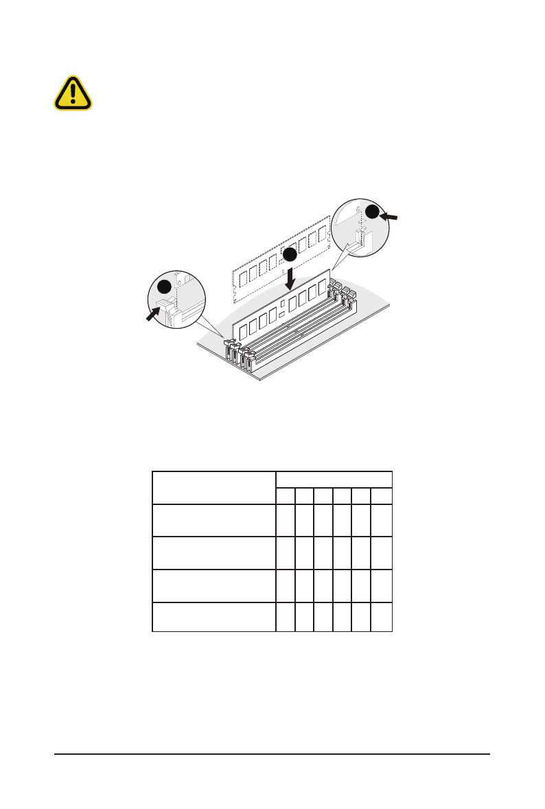
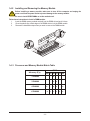
1-4-2 Installing and Removing the Memory Module
Before installing a memory module, make sure to turn off the computer and unplug the
power cord from the power outlet to prevent damage to the memory module.
Be sure to install DDR5 DIMMs on to this motherboard.
Follow these instructions to install a DIMM module:
1. Insert the DIMM memory module vertically into the DIMM slot and push it down.
2. Close the plastic clip at both edges of the DIMM slots to lock the DIMM module.
3. Reverse the installation steps when you want to remove the DIMM module.
1
2
2
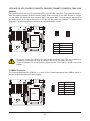
1-4-3 Processor and Memory Module Matrix Table
4 DIMM
Memory Q’ty H0
F0B0D0 E0A0
1 DIMM
2 DIMM
6 DIMM
CPU0
V
VV
V
V
VV
V
VV
V
V V
- 15 -
Hardware Installation
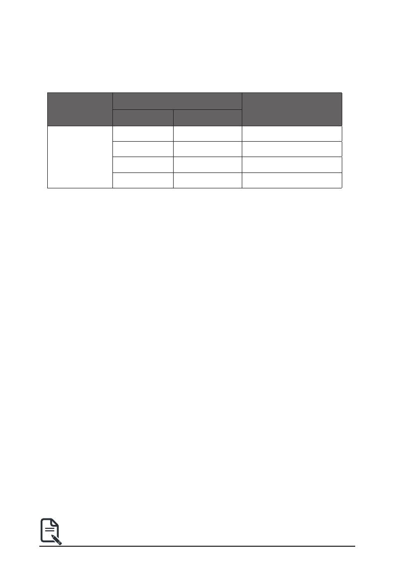
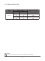
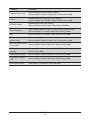
Note:
• When only one DIMM per channel is used, it must be populated in memory slot DIMM1.
DIMM
Type
DIMM Population
DDR5 Frequency (MT/s)
DIMM 0 DIMM 1
RDIMM
-- 1R 4800
1R 1R 4000
-- 2R 4800
2R 2R 3600
1-4-4 Memory Population Table
- 16 -
Hardware Installation
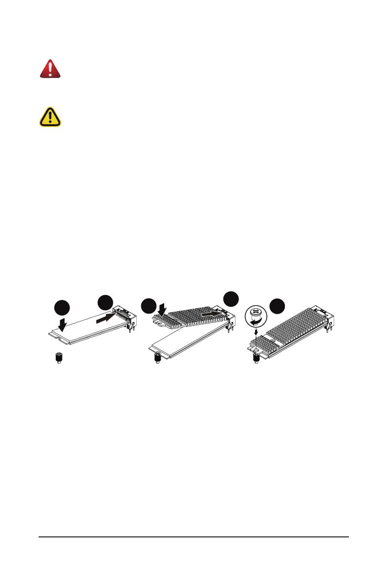
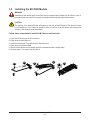
1-5 Installing the M.2 SSD Module
Follow these instructions to install the M.2 device and heat sink:
1. Insert the M.2 device into the M.2 connector.
2. Press down on the M.2 device.
3. Install the thermal pad of the M.2 device to the M.2 device.
4. Press down on the thermal pad.
5. Secure the M.2 device and its thermal pad to the motherboard with a single screw.
6. Reverse steps 1-5 to remove the M.2 device.
WARNING
Installation of the thermal pad over the M.2 device is required when installing an M.2 device. Lack of
the thermal pad may result in the system overheating and throttle the system performance.
CAUTION
The position of the stand-off screw will depend on the size of the M.2 device. The stand-off screw
is pre-installed for 22110 cards as standard. Refer to the size of the M.2 device and change the
position of the stand-off screw accordingly.
14
2
3
5
- 17 -
Hardware Installation
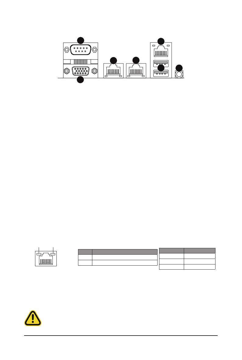
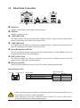
1-6 Back Panel Connectors
uSerial Port
Connect to serial-based mouse or data processing devices.
vVGA Port
Connect to a monitor device.
w1 GbE LAN Port #2
The Gigabit Ethernet LAN port provides Internet connection at up to 1 Gbps data rate. See the section
below for a description of the states of the LAN port LEDs.
x1 GbE LAN Port #1
The Gigabit Ethernet LAN port provides Internet connection at up to 1 Gbps data rate. See the section
below for a description of the states of the LAN port LEDs.
yServer Management LAN Port
The LAN port provides Internet connection with data transfer speeds of 10/100/1000Mbps. This port is
the dedicated LAN port for Server Management.
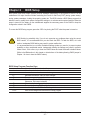
zUSB 3.2 Gen1 Ports
The USB port supports the USB 3.2 specification. Use this port for USB devices such as a USB
keyboard/mouse,USBprinter,USBashdriveetc.
{ID button with LED
Whenthesystemidenticationisactive,theIDLEDonthefront/backpanelglowsblue.
LAN and ID Button LEDs
Link/Activity LED
Speed LED
LAN Port
• Whenremovingthecableconnectedtoabackpanelconnector,rstremovethecablefromyour
device and then remove it from the motherboard.
• When removing the cable, pull it straight out from the connector. Do not rock it side to side to
prevent an electrical short inside the cable connector.
ID button/LED: 10/100/1000 LAN LED:
State Description
Yellow On 1Gbps data rate
Green On 100Mbps data rate
Off 10Mbps data rate
State Description
Blue On Systemidenticationisactive
Off Systemidenticationisdisabled
1
2
34
5
7
6

- 18 -
Hardware Installation
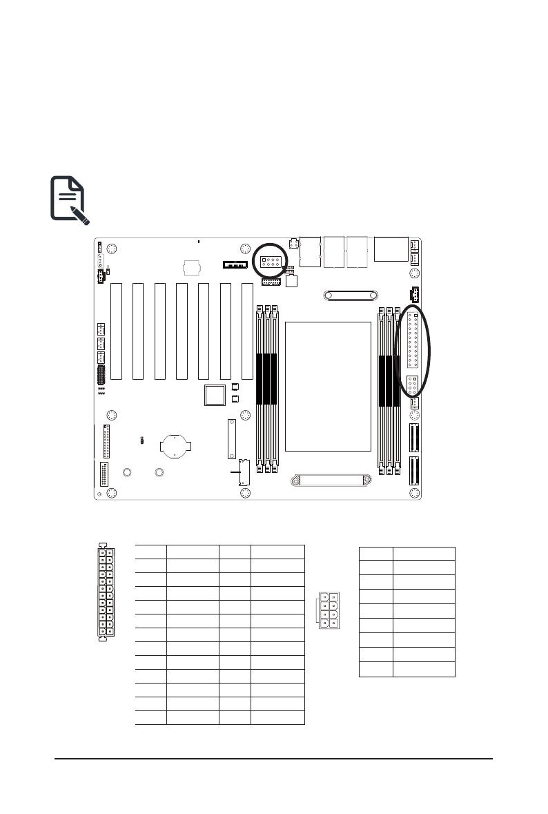
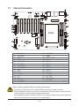
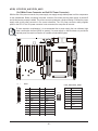
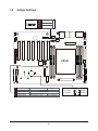
1-7 Internal Connectors
Read the following guidelines before connecting external devices:
• First make sure your devices are compliant with the connectors you wish to connect.
• Before installing the devices, be sure to turn off the devices and your computer. Unplug the power
cord from the power outlet to prevent damage to the devices.
• After installing the device and before turning on the computer, make sure the device cable has
been securely attached to the connector on the motherboard.
1
2
3
4
5
6
7
12 10
11 8
9
15
16
17 18
19 23
22
21
20 24
28
26
25
13
14
29
CPU0
DIMM_P0_B0
DIMM_P0_D0
DIMM_P0_A0
DIMM_P0_E0
DIMM_P0_H0
DIMM_P0_F0
27
1) SYS_FAN1 16) SYS_FAN2
2) SYS_FAN3 17) IPMB1
3) PMBUS 18) CASE_OPEN1
4) ATX1 19) PCIe_1
5) P12V_ AUX1 20) PCIe_2
6) CPU_FAN1 21) PCIe_3
7) U2_P0_G3A 22) PCIe_4
8) U2_P0_G3B 23) PCIe_5
9) M2_0 24) PCIe_6
10) BAT 25) PCIe_7
11) F_USB3_1 26) CN_NCSI1
12) FP_1 27) SPI_TPM
13) BP_1 28) P12V_AUX2
14) SYS_FAN4 29) LED_BMC
15) SYS_FAN5

- 19 -
Hardware Installation
CPU0
DIMM_P0_B0
DIMM_P0_D0
DIMM_P0_A0
DIMM_P0_E0
DIMM_P0_H0
DIMM_P0_F0
CPU0
DIMM_P0_B0
DIMM_P0_D0
DIMM_P0_A0
DIMM_P0_E0
DIMM_P0_H0
DIMM_P0_F0
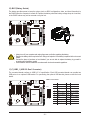
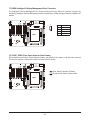
1/2/6/14/15/16) SYS_FAN1/SYS_FAN3/CPU_FAN1/SYS_FAN4/SYS_FAN5/SYS_FAN6 (FAN
Headers)
Themotherboardhasone4-pinCPUfanheader(CPU_FAN),andve4-pin(SYS_FAN)systemfanheaders.
Most fan headers possess a foolproof insertion design. When connecting a fan cable, be sure to connect
it in the correct orientation (the black connector wire is the ground wire). The motherboard supports CPU
fan speed control, which requires the use of a CPU fan with fan speed control design. For optimum heat
dissipation, it is recommended that a system fan be installed inside the chassis.
1
1
PinNo. Denition
1 GND
2 +12V
3 Sense
4 Speed Control
• Be sure to connect fan cables to the fan headers to prevent your CPU and system from
overheating. Overheating may result in damage to the CPU or the system may hang.
• Thesefanheadersarenotconfigurationjumperblocks.Donotplaceajumpercaponthe
headers.
4
4
3) PMBus Connector
The Power Management Bus (PMBus) is a variant of the System Management Bus (SMBus) which is
targeted at digital management of power supplies.
5
1
PinNo. Denition
1 PMBus Clock
2 PMBus Data
3 PMBus Alert
4 GND
5 3.3V Sense
- 20 -
Hardware Installation
CPU0
DIMM_P0_B0
DIMM_P0_D0
DIMM_P0_A0
DIMM_P0_E0
DIMM_P0_H0
DIMM_P0_F0
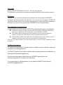
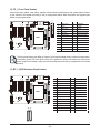
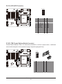
4/5/28) ATX1/P12V_AUX1/P12V_AUX2
(2x12 Main Power Connector and 2x4 12V Power Connector)
With the use of the power connector, the power supply can supply enough stable power to all the components
onthemotherboard.Beforeconnectingthepowerconnector,rstmakesurethepowersupplyisturnedoff
and all devices are properly installed. The power connector possesses a foolproof design. Connect the power
supply cable to the power connector in the correct orientation. The 12V power connector mainly supplies
power to the CPU. If the 12V power connector is not connected, the computer will not start.
To meet expansion requirements, it is recommended that a power supply that can withstand high
power consumption be used (500W or greater). If a power supply is used that does not provide the
required power, the result can lead to an unstable or unbootable system.
ATX1 P12V_AUX1/P12V_AUX2
8
5
4
1
PinNo. Denition
1 GND
2 GND
3 GND
4 GND
5 +12V
6 +12V
7 +12V
8 +12V
Pin No. Denition Pin No. Denition
1 3.3V 13 3.3V
2 3.3V 14 -12V
3 GND 15 GND
4 +5V 16 PS_ON
5 GND 17 GND
6 +5V 18 GND
7 GND 19 GND
8 Power Good 20 -5V
9 5VSB 21 +5V
10 +12V 22 +5V
11 +12V 23 +5V
12 3.3V 24 GND
113
1224
Page is loading ...
Page is loading ...
Page is loading ...
Page is loading ...
Page is loading ...
Page is loading ...
Page is loading ...
Page is loading ...
Page is loading ...
Page is loading ...
Page is loading ...
Page is loading ...
Page is loading ...
Page is loading ...
Page is loading ...
Page is loading ...
Page is loading ...
Page is loading ...
Page is loading ...
Page is loading ...
Page is loading ...
Page is loading ...
Page is loading ...
Page is loading ...
Page is loading ...
Page is loading ...
Page is loading ...
Page is loading ...
Page is loading ...
Page is loading ...
Page is loading ...
Page is loading ...
Page is loading ...
Page is loading ...
Page is loading ...
Page is loading ...
Page is loading ...
Page is loading ...
Page is loading ...
Page is loading ...
Page is loading ...
Page is loading ...
Page is loading ...
Page is loading ...
Page is loading ...
Page is loading ...
Page is loading ...
Page is loading ...
Page is loading ...
Page is loading ...
Page is loading ...
Page is loading ...
Page is loading ...
Page is loading ...
Page is loading ...
Page is loading ...
Page is loading ...
Page is loading ...
Page is loading ...
Page is loading ...
Page is loading ...
Page is loading ...
Page is loading ...
Page is loading ...
Page is loading ...
Page is loading ...
Page is loading ...
Page is loading ...
Page is loading ...
Page is loading ...
Page is loading ...
Page is loading ...
Page is loading ...
Page is loading ...
Page is loading ...
Page is loading ...
Page is loading ...
Page is loading ...
Page is loading ...
Page is loading ...
Page is loading ...
Page is loading ...
Page is loading ...
Page is loading ...
Page is loading ...
Page is loading ...
Page is loading ...
Page is loading ...
Page is loading ...
Page is loading ...
Page is loading ...
Page is loading ...
Page is loading ...
Page is loading ...
Page is loading ...
Page is loading ...
Page is loading ...
Page is loading ...
Page is loading ...
Page is loading ...
Page is loading ...
Page is loading ...
Page is loading ...
Page is loading ...
Page is loading ...
Page is loading ...
Page is loading ...
Page is loading ...
Page is loading ...
Page is loading ...
Page is loading ...
Page is loading ...
Page is loading ...
Page is loading ...
Page is loading ...
Page is loading ...
Page is loading ...
-
 1
1
-
 2
2
-
 3
3
-
 4
4
-
 5
5
-
 6
6
-
 7
7
-
 8
8
-
 9
9
-
 10
10
-
 11
11
-
 12
12
-
 13
13
-
 14
14
-
 15
15
-
 16
16
-
 17
17
-
 18
18
-
 19
19
-
 20
20
-
 21
21
-
 22
22
-
 23
23
-
 24
24
-
 25
25
-
 26
26
-
 27
27
-
 28
28
-
 29
29
-
 30
30
-
 31
31
-
 32
32
-
 33
33
-
 34
34
-
 35
35
-
 36
36
-
 37
37
-
 38
38
-
 39
39
-
 40
40
-
 41
41
-
 42
42
-
 43
43
-
 44
44
-
 45
45
-
 46
46
-
 47
47
-
 48
48
-
 49
49
-
 50
50
-
 51
51
-
 52
52
-
 53
53
-
 54
54
-
 55
55
-
 56
56
-
 57
57
-
 58
58
-
 59
59
-
 60
60
-
 61
61
-
 62
62
-
 63
63
-
 64
64
-
 65
65
-
 66
66
-
 67
67
-
 68
68
-
 69
69
-
 70
70
-
 71
71
-
 72
72
-
 73
73
-
 74
74
-
 75
75
-
 76
76
-
 77
77
-
 78
78
-
 79
79
-
 80
80
-
 81
81
-
 82
82
-
 83
83
-
 84
84
-
 85
85
-
 86
86
-
 87
87
-
 88
88
-
 89
89
-
 90
90
-
 91
91
-
 92
92
-
 93
93
-
 94
94
-
 95
95
-
 96
96
-
 97
97
-
 98
98
-
 99
99
-
 100
100
-
 101
101
-
 102
102
-
 103
103
-
 104
104
-
 105
105
-
 106
106
-
 107
107
-
 108
108
-
 109
109
-
 110
110
-
 111
111
-
 112
112
-
 113
113
-
 114
114
-
 115
115
-
 116
116
-
 117
117
-
 118
118
-
 119
119
-
 120
120
-
 121
121
-
 122
122
-
 123
123
-
 124
124
-
 125
125
-
 126
126
-
 127
127
-
 128
128
-
 129
129
-
 130
130
-
 131
131
-
 132
132
-
 133
133
-
 134
134
-
 135
135
-
 136
136
-
 137
137


