Gigabyte GA-Z170X-SOC FORCE Owner's manual
- Category
- Server/workstation motherboards
- Type
- Owner's manual

GA-Z170X-SOC Force
User's Manual
Rev. 1001
12ME-Z17XSOF-1001R
For more product details, please visit GIGABYTE's website.
To reduce the impacts on global warming, the packaging materials of this product are
recyclable and reusable. GIGABYTE works with you to protect the environment.

Motherboard
GA-Z170X-SOC Force
Sept. 18, 2015
Sept. 18, 2015
Motherboard
GA-Z170X-SOC Force

Copyright
© 2015 GIGA-BYTE TECHNOLOGY CO., LTD. All rights reserved.
The trademarks mentioned in this manual are legally registered to their respective owners.
Disclaimer
Information in this manual is protected by copyright laws and is the property of GIGABYTE.
Changes to the specications and features in this manual may be made by GIGABYTE
without prior notice.
No part of this manual may be reproduced, copied, translated, transmitted, or published in any
form or by any means without GIGABYTE's prior written permission.
Documentation Classications
In order to assist in the use of this product, GIGABYTE provides the following types of
documentations:
For quick set-up of the product, read the Quick Installation Guide included with the product.
For detailed product information, carefully read the User's Manual.
For product-related information, check on our website at: http://www.gigabyte.com
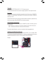
Identifying Your Motherboard Revision
The revision number on your motherboard looks like this: "REV: X.X." For example, "REV:
1.0" means the revision of the motherboard is 1.0. Check your motherboard revision before
updating motherboard BIOS, drivers, or when looking for technical information.
Example:

- 4 -
Table of Contents
Box Contents ...................................................................................................................6
Optional Items .................................................................................................................6
GA-Z170X-SOC Force Motherboard Layout ...................................................................7
Chapter 1 Hardware Installation .....................................................................................9
1-1 Installation Precautions .................................................................................... 9
1-2 ProductSpecications .................................................................................... 10
1-3 Installing the CPU and CPU Cooler ............................................................... 14
1-3-1 Installing the CPU ...................................................................................................14
1-3-2 Installing the CPU Cooler .......................................................................................16
1-4 Installing the Memory ..................................................................................... 17
1-4-1 DualChannelMemoryConguration .....................................................................17
1-4-2 Installing a Memory ................................................................................................18
1-5 Installing an Expansion Card ......................................................................... 19
1-6 Setting up AMD CrossFire™/NVIDIA® SLI™Conguration .............................. 20
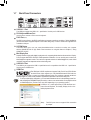
1-7 Back Panel Connectors .................................................................................. 22
1-8 Onboard Buttons, Switches, and LEDs .......................................................... 24
1-9 Internal Connectors ........................................................................................ 27
Chapter 2 BIOS Setup ..................................................................................................41
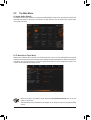
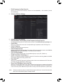
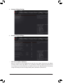
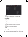
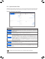
2-1 Startup Screen ............................................................................................... 42
2-2 The Main Menu .............................................................................................. 43
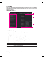
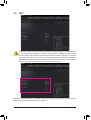
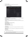
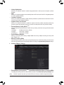
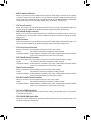
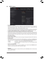
2-3 M.I.T. .............................................................................................................. 45
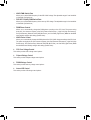
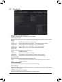
2-4 System Information ........................................................................................ 58
2-5 BIOS Features ............................................................................................... 59
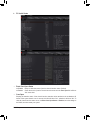
2-6 Peripherals ..................................................................................................... 62
2-7 Chipset ........................................................................................................... 65
2-8 Power Management ....................................................................................... 66
2-9 Save & Exit ..................................................................................................... 68
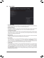
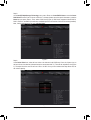
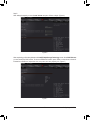
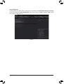
Chapter3 ConguringaRAIDSet ................................................................................ 69
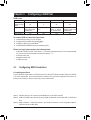
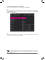
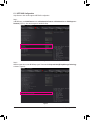
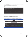
3-1 ConguringSATAControllers ......................................................................... 69
3-2 InstallingtheSATARAID/AHCIDriverandOperatingSystem ....................... 81
Chapter 4 Drivers Installation ........................................................................................85
4-1 Drivers & Software ......................................................................................... 85
4-2 Application Software ...................................................................................... 86
4-3 Information ..................................................................................................... 86

- 5 -
Chapter 5 Unique Features ...........................................................................................87
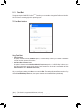
5-1 BIOS Update Utilities ..................................................................................... 87
5-1-1 Updating the BIOS with the Q-Flash Utility .............................................................87
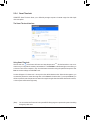
5-1-2 Updating the BIOS with the @BIOS Utility .............................................................90
5-1-3 Using Q-Flash Plus .................................................................................................91
5-1-4 Using GIGABYTE HW OC ......................................................................................92
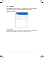
5-2 APP Center .................................................................................................... 93
5-2-1 EasyTune................................................................................................................94
5-2-2 System Information Viewer .....................................................................................95
5-2-3 Fast Boot ................................................................................................................96
5-2-4 Smart TimeLock......................................................................................................97
5-2-5 USB Blocker ...........................................................................................................98
5-2-6 Smart Keyboard ......................................................................................................99
5-2-7 Smart Backup .......................................................................................................100
5-2-8 Ambient LED ........................................................................................................102
5-2-9 3D OSD ................................................................................................................103
5-2-10 Cloud Station ........................................................................................................104
5-2-11 AutoGreen ............................................................................................................109
5-2-12 EasyRAID ............................................................................................................110
5-3 Smart Switch ................................................................................................ 113
Chapter 6 Appendix .................................................................................................... 115
6-1 ConguringAudioInputandOutput ............................................................. 115
6-1-1 Conguring2/4/5.1/7.1-ChannelAudio .................................................................115
6-1-2 ConguringS/PDIFOut ........................................................................................ 117
6-1-3 ConguringMicrophoneRecording ......................................................................118
6-1-4 UsingtheSoundRecorder ...................................................................................120
6-2 Troubleshooting............................................................................................ 121
6-2-1 Frequently Asked Questions ................................................................................ 121
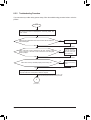
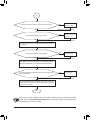
6-2-2 Troubleshooting Procedure ..................................................................................122
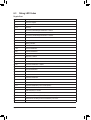
6-3 Debug LED Codes ....................................................................................... 124
RegulatoryStatements ............................................................................................ 128
Contact Us .............................................................................................................. 131

- 6 -
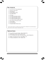
Box Contents
5GA-Z170X-SOC Force motherboard
5Motherboard driver disk
5User's Manual
5Quick Installation Guide
5Four SATA cables
5I/O Shield
5One 2-Way SLI bridge connector
5One 3-Way SLI bridge connector
5One 4-Way SLI bridge connector
5One 2-Way CrossFire bridge connector
5Eight voltage measurement cables
5One OC Brace
5One G Connector
5One pack of back I/O dust covers
Optional Items
2-portUSB2.0bracket(PartNo.12CR1-1UB030-6*R)
eSATAbracket(PartNo.12CF1-3SATPW-4*R)
3.5"FrontPanelwith2USB3.0/2.0ports(PartNo.12CR1-FPX582-2*R)
HDMI-to-DVIadapter(PartNo.12CT2-HDMI01-1*R)
COMportcable(PartNo.12CF1-1CM001-3*R)
The box contents above are for reference only and the actual items shall depend on the product package you
obtain. The box contents are subject to change without notice.

- 7 -
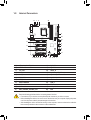
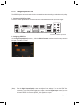
GA-Z170X-SOC Force Motherboard Layout
(Note) Fordebugcodeinformation,pleaserefertoChapter6.
PCIE_SW
ATX_12V_2X4
ATX
AUDIO
Intel® Z170
LGA1151
KB_MS_USB
CODEC
F_PANEL
Intel® GbE
LAN
USB30_LAN
_
PCIEX16_1
OCPSW
SB
SPDIF_O
F_AUDIO
CLR_CMOS
PCIEX1_3
+
M_BIOS
B_BIOS
F_USB1
SATA3
GA-Z170X-SOC Force
+_
MDP
R_USB30_2
CPU_FAN
M2C_32G
PCIEX1_1
PCIEX1_2
PCIEX16_2
PW_SW
RATIO_DW
RATIO_UP
FREQ_DW
FREQ_UP
GEAR
TAG
OC_IGNITION
TURBO
RST_SW
DTB
CMOS_SW
BIOS_SW
TGR
CBAT_SW
SET_LOCK
MEM_SAFE
F_USB3
Debug LED (Note)
TPM
COMA
SYS_FAN4
SATAEXPRESS
5 4
1 0
BBIOS_LED
MBIOS_LED
DDR4_4
DDR4_2
DDR4_3
DDR4_1
FBIOS_LED
CPU_OPT
ATX_12V
SYS_FAN2
THB_C
F_USB2 SYS_FAN3
M2D_32GM2A_32G
F_USB4
OC_PEG
PCIEX8_1
PCIEX8_2
SATAEXPRESS
7 6
3 2
LED_CON1
SYS_FAN1
DVI
R_USB30_1 Intel®
USB 3.1 Controller
SYS_FAN6
PEX8747
SYS_FAN5
Renesas®
uPD720210
ASMedia®
ASM1061
F_USB30_1
F_USB30_2
42A60A80A
42D60D80D
42C60C80C
HDMI
TYPEC
BAT
System Temp. Sensor 1
System Temp. Sensor 2
iTE® Super I/O

- 8 -

- 9 -
Hardware Installation
Chapter 1 Hardware Installation
1-1 Installation Precautions
The motherboard contains numerous delicate electronic circuits and components which can become
damagedasaresultofelectrostaticdischarge(ESD).Priortoinstallation,carefullyreadtheuser's
manual and follow these procedures:
•Prior to installation, make sure the chassis is suitable for the motherboard.
•Priortoinstallation,donotremoveorbreakmotherboard S/N (Serial Number) sticker or
warranty sticker provided by your dealer. These stickers are required for warranty validation.
•Always remove the AC power by unplugging the power cord from the power outlet before
installing or removing the motherboard or other hardware components.
•When connecting hardware components to the internal connectors on the motherboard, make
sure they are connected tightly and securely.
•When handling the motherboard, avoid touching any metal leads or connectors.
•Itisbesttowearanelectrostaticdischarge(ESD)wriststrapwhenhandlingelectroniccom-
ponents such as a motherboard, CPU or memory. If you do not have an ESD wrist strap, keep
yourhandsdryandrsttouchametalobjecttoeliminatestaticelectricity.
•Prior to installing the motherboard, please have it on top of an antistatic pad or within an
electrostatic shielding container.
•Before connecting or unplugging the power supply cable from the motherboard, make sure
the power supply has been turned off.
•Before turning on the power, make sure the power supply voltage has been set according to
the local voltage standard.
•Before using the product, please verify that all cables and power connectors of your hardware
components are connected.
•To prevent damage to the motherboard, do not allow screws to come in contact with the
motherboard circuit or its components.
•Make sure there are no leftover screws or metal components placed on the motherboard or
within the computer casing.
•Do not place the computer system on an uneven surface.
•Do not place the computer system in a high-temperature or wet environment.
•Turning on the computer power during the installation process can lead to damage to system
components as well as physical harm to the user.
•If you are uncertain about any installation steps or have a problem related to the use of the
product,pleaseconsultacertiedcomputertechnician.
•If you use an adapter, extension power cable, or power strip, ensure to consult with its instal-
lation and/or grounding instructions.

- 10 -Hardware Installation
1-2 ProductSpecications
CPU Support for Intel® Core™ i7 processors/Intel® Core™ i5 processors/
Intel® Core™ i3 processors/Intel® Pentium® processors/
Intel® Celeron® processors in the LGA1151 package
(GotoGIGABYTE'swebsiteforthelatestCPUsupportlist.)
L3 cache varies with CPU
Chipset
Intel® Z170 Express Chipset
Memory 4xDDR4DIMMsocketssupportingupto64GBofsystemmemory
* DuetoaWindows32-bitoperatingsystemlimitation,whenmorethan4GBofphysical
memory is installed, the actual memory size displayed will be less than the size of
the physical memory installed.
Dual channel memory architecture
SupportforDDR42133MHzmemorymodules
SupportforECCUDIMM1Rx8/2Rx8memorymodules(operateinnon-ECCmode)
Supportfornon-ECCUDIMM1Rx8/2Rx8/1Rx16memorymodules
SupportforExtremeMemoryProle(XMP)memorymodules
(Go to GIGABYTE's website for the latest supported memory speeds and memory
modules.)
Onboard
Graphics
Integrated Graphics Processor-Intel® HD Graphics support:
- 1 x DVI-D port, supporting a maximum resolution of 1920x1200@60 Hz
* TheDVI-DportdoesnotsupportD-Subconnectionbyadapter.
-
1 x Mini-DisplayPort, supporting a maximum resolution of 4096x2304@60 Hz
* SupportforDisplayPort1.2version.
- 1 x HDMI port, supporting a maximum resolution of 4096x2160@24 Hz
* SupportforHDMI1.4version.
Support for up to 3 displays at the same time
Maximum shared memory of 512 MB
Audio
Realtek® ALC1150 codec
High Denition Audio
2/4/5.1/7.1-channel
Support for S/PDIF Out
LAN
Intel® GbE LAN chip (10/100/1000 Mbit)
Expansion Slots 2xPCIExpressx16slots,runningatx16(PCIEX16_1,PCIEX16_2)
* Foroptimumperformance,ifonlyonePCIExpressgraphicscardistobeinstalled,be
sure to install it in the PCIEX16_1 slot; if you are installing two PCI Express graphics
cards, it is recommended that you install them in the PCIEX16_1 and PCIEX16_2
slots.
2xPCIExpressx16slots,runningatx8(PCIEX8_1,PCIEX8_2)
* ThePCIEX8_1slotsharesbandwidthwiththePCIEX16_1slotandthePCIEX8_2
slot with PCIEX16_2. The PCIEX16_1/PCIEX16_2 slot will operate at up to x8 mode
when the PCIEX8_1/PCIEX8_2 is populated.
3 x PCI Express x1 slots
(AllofthePCIExpressslotsconformtoPCIExpress3.0standard.)
Multi-Graphics
Technology Support for 4-Way/3-Way/2-Way AMD CrossFire™/NVIDIA® SLI™ technology

- 11 -
Hardware Installation
Storage Interface Chipset:
- 3 x M.2 Socket 3 connectors
- 3 x SATA Express connectors
- 6 x SATA 6Gb/s connectors (SATA3 0~5)
- Support for RAID 0, RAID 1, RAID 5, and RAID 10
* Refer to"1-9Internal Connectors,"forthesupportedcongurationswiththeM.2,
SATA Express, and SATA connectors.
ASMedia® ASM1061 chip:
- 2 x SATA 6Gb/s connectors (SATA3 6~7), supporting AHCI mode only
USB Chipset+Intel® USB 3.1 Controller:
- 1 x USB Type-C™portonthebackpanel,withUSB3.1support
- 1 x USB 3.1 port on the back panel
Chipset:
- 5 x USB 3.0/2.0 ports on the back panel
- 8 x USB 2.0/1.1 ports (2 ports on the back panel, 2 ports onboard, 4 ports
available through the internal USB headers)
Chipset+Renesas® USB 3.0 Hub:
- 4 x USB 3.0/2.0 ports (available through the internal USB headers)
Internal
Connectors
1 x 24-pin ATX main power connector
1 x 8-pin ATX 12V power connector
1x4-pinATX12Vpowerconnector
1 x OC PEG Power Connector
3 x SATA Express connectors
8 x SATA 6Gb/s connectors
3 x M.2 Socket 3 connectors
1 x CPU fan header
1xwatercoolingfanheader(CPU_OPT)
6 x system fan headers
1xI/OshieldaudioLEDpowerconnector
1 x Thunderbolt™ add-in card connector
* Doesnotsupportdeviceplugandplayaswellassurpriseremovalwhilesystemis
poweredon.
1 x front panel header
1 x front panel audio header
1 x S/PDIF Out header
2 x USB 3.0/2.0 headers
2 x USB 2.0/1.1 headers
2 x USB 2.0/1.1 ports
1 x Trusted Platform Module (TPM) header
1 x serial port header
1 x Clear CMOS jumper
1 x power button
1 x reset button
1 x Clear CMOS button
1 x Gear button
1 x OC Tag button
1 x OC Trigger switch

- 12 -
Hardware Installation
Internal
Connectors
1 x CPU BCLK Down button
1 x CPU BCLK Up button
1 x CPU Ratio Down button
1 x CPU Ratio Up button
1 x Settings Lock button
1 x Direct to BIOS button
1 x Memory Safe button
1 x OC PCIe switch
1 x OC Ignition button
1 x Clear Battery button
1 x DualBIOS switch
1 x BIOS switch
1 x onboard voltage measurement module
Back Panel
Connectors
2 x USB 2.0/1.1 ports
1 x PS/2 keyboard/mouse port
1 x DVI-D port
1 x OCPSW button
1 x Mini-DisplayPort
1 x HDMI port
5 x USB 3.0/2.0 ports
1 x USB Type-C ™ port, with USB 3.1 support
1 x USB 3.1 port
1 x RJ-45 port
1 x optical S/PDIF Out connector
5 x audio jacks (Center/Subwoofer Speaker Out, Rear Speaker Out, Line In,
Line Out, Mic In)
I/O Controller iTE I/O Controller Chip
Hardware
Monitor
System voltage detection
CPU/System/Chipset temperature detection
CPU/CPU OPT/System fan speed detection
CPU/System/Chipset overheating warning
CPU/CPU OPT/System fan fail warning
CPU/CPU OPT/System fan speed control
* Whether the fan speed control function is supported will depend on the cooler you
install.
BIOS 2 x 128 Mbit flash
Use of licensed AMI UEFI BIOS
Support for DualBIOS™
Support for Q-Flash Plus
* The USB flash drive used must be a USB 2.0 flash drive.
PnP 1.0a, DMI 2.7, WfM 2.0, SM BIOS 2.7, ACPI 5.0
Unique Features Support for APP Center
* Available applications in APP Center may vary by motherboard model. Supported
functions of each application may also vary depending on motherboard specications.
- 3D OSD
- @BIOS
- Ambient LED
- AutoGreen

- 13 -
Hardware Installation
PleasevisitGIGABYTE'swebsiteforsupportlistsofCPU,memorymodules,SSDs,andM.2
devices.
Unique Features - Cloud Station
- EasyTune
- Easy RAID
- Fast Boot
- Smart TimeLock
- Smart Keyboard
- Smart Backup
- SystemInformationViewer
- USB Blocker
Support for Q-Flash
Support for Smart Switch
Support for Xpress Install
Support for GIGABYTE HW OC
* Please download the app from Google Play or App Store to your smart phone/tablet
device.
Bundled
Software
Norton® Internet Security (OEM version)
Intel® Smart Response Technology
cFosSpeed
Operating
System
Support for Windows 10/8.1/7
* Please download the "Windows USB Installation Tool" from GIGABYTE's website
and install it before installing Windows 7.
Form Factor E-ATX Form Factor; 30.5cm x 26.4cm
* GIGABYTE reserves the right to make any changes to the product specications and product-related information without
prior notice.
Please visit the Support\Utility ListpageonGIGABYTE's website to download the latest
version of apps.

- 14 -Hardware Installation
1-3 Installing the CPU and CPU Cooler
ReadthefollowingguidelinesbeforeyoubegintoinstalltheCPU:
•Make sure that the motherboard supports the CPU.
(GotoGIGABYTE'swebsiteforthelatestCPUsupportlist.)
•Always turn off the computer and unplug the power cord from the power outlet before installing the
CPU to prevent hardware damage.
•Locate the pin one of the CPU. The CPU cannot be inserted if oriented incorrectly. (Or you may
locatethenotchesonbothsidesoftheCPUandalignmentkeysontheCPUsocket.)
•Apply an even and thin layer of thermal grease on the surface of the CPU.
•Do not turn on the computer if the CPU cooler is not installed, otherwise overheating and damage
of the CPU may occur.
•SettheCPUhostfrequencyinaccordancewiththeCPUspecications.Itisnotrecommended
thatthesystembusfrequencybesetbeyondhardwarespecicationssinceitdoesnotmeetthe
standard requirements for the peripherals. If you wish to set the frequency beyond the standard
specications,pleasedosoaccordingtoyourhardwarespecicationsincludingtheCPU,graphics
card, memory, hard drive, etc.
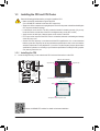
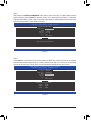
1-3-1 Installing the CPU
A. Locate the alignment keys on the motherboard CPU socket and the notches on the CPU.
Alignment KeyAlignment Key
LGA1151 CPU
LGA1151 CPU Socket
Pin One Corner of the CPU Socket
Triangle Pin One Marking on the CPU
Notch
Notch
Please visit GIGABYTE's website for details on hardware installation.

- 15 -
Hardware Installation
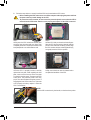
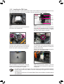
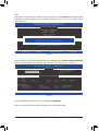
B. Follow the steps below to correctly install the CPU into the motherboard CPU socket.
Step 1:
Gently press the CPU socket lever handle down
andawayfromthesocketwithyournger.Then
completely lift the CPU socket lever and the metal
load plate/plastic cover will be lifted as well.
Step 2:
HoldtheCPUwithyourthumbandindexngers.
AligntheCPUpinonemarking(triangle)withthe
pin one corner of the CPU socket (or you may align
theCPUnotcheswiththesocketalignmentkeys)
and gently insert the CPU into position.
Step 4:
Finally, secure the lever under its retention tab to
complete the installation of the CPU.
NOTE:
Hold the CPU socket lever by the handle, not the lever base portion.
•Before installing the CPU, make sure to turn off the computer and unplug the power cord from
the power outlet to prevent damage to the CPU.
•To protect the socket contacts, do not remove the protective plastic cover unless the CPU is
inserted into the CPU socket. Save the cover properly and replace it if the CPU is removed.
Step 3:
Once the CPU is properly inserted, carefully
replace the load plate. When replacing the load
plate, make sure the front end of the load plate
is under the shoulder screw. Then press the CPU
socket lever. The protective plastic cover may
pop off from the load plate during the process of
engagingthelever.Removethecover.(Savethe
cover properly and always replace it when the
CPUisnotinstalled.)

- 16 -Hardware Installation
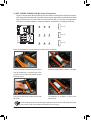
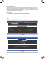
1-3-2 Installing the CPU Cooler
RefertothestepsbelowtocorrectlyinstalltheCPUcooleronthemotherboard.(Actualinstallationprocessmay
differdependingtheCPUcoolertobeused.Refertotheuser'smanualforyourCPUcooler.)
Step 5:
After the installation, check the back of the moth-
erboard. If the push pin is inserted as the picture
above shows, the installation is complete.
Step 6:
Finally, attach the power connector of the CPU
coolertotheCPUfanheader(CPU_FAN)onthe
motherboard.
Step 1:
Apply an even and thin layer of thermal grease on
the surface of the installed CPU.
Step 2:
Before installing the cooler, note the direction of the
arrow sign on the male push pin. (Turning the
push pin along the direction of arrow is to remove
thecooler,onthecontrary,istoinstall.)
Step 3:
Place the cooler atop the CPU, aligning the four
push pins through the pin holes on the mother-
board. Push down on the push pins diagonally.
Step 4:
You should hear a "click" when pushing down each
push pin. Check that the Male and Female push
pins are joined closely.
(RefertoyourCPUcoolerinstallationmanualfor
instructionsoninstallingthecooler.)
Male
Push Pin
Female
Push Pin
The Top
of Female
Push Pin
Direction of
the Arrow Sign
on the Male
Push Pin
•Use extreme care when removing the CPU cooler because the thermal grease/tape between
the CPU cooler and CPU may adhere to the CPU. Inadequately removing the CPU cooler may
damage the CPU.
•ThismotherboardprovidestwoG1/4″threadedttings.Pleasechoosethebarbs(notincluded)thatsuit
your requirements.

- 17 -
Hardware Installation
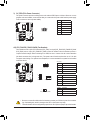
DDR4_4
DDR4_2
DDR4_3
DDR4_1
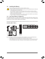
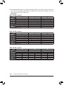
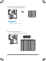
1-4-1 DualChannelMemoryConguration
This motherboard provides four memory sockets and supports Dual Channel Technology. After the memory
isinstalled,theBIOSwillautomaticallydetectthespecicationsandcapacityofthememory.EnablingDual
Channel memory mode will double the original memory bandwidth.
The four memory sockets are divided into two channels and each channel has two memory sockets as following:
ChannelA:DDR4_2,DDR4_4
ChannelB:DDR4_1,DDR4_3
DualChannelMemoryCongurationsTable
DDR4_4 DDR4_2 DDR4_3 DDR4_1
2 Modules - - DS/SS - - DS/SS
DS/SS - - DS/SS - -
4 Modules DS/SS DS/SS DS/SS DS/SS
(SS=Single-Sided,DS=Double-Sided,"--"=NoMemory)
Due to CPU limitations, read the following guidelines before installing the memory in Dual Channel mode.
1. Dual Channel mode cannot be enabled if only one memory module is installed.
2. When enabling Dual Channel mode with two or four memory modules, it is recommended that memory
of the same capacity, brand, speed, and chips be used and installed in the same colored sockets.
1-4 Installing the Memory
Readthefollowingguidelinesbeforeyoubegintoinstallthememory:
•Make sure that the motherboard supports the memory. It is recommended that memory of the same
capacity, brand, speed, and chips be used.
(GotoGIGABYTE'swebsiteforthelatestsupportedmemoryspeedsandmemorymodules.)
•Always turn off the computer and unplug the power cord from the power outlet before installing the
memory to prevent hardware damage.
•Memory modules have a foolproof design. A memory module can be installed in only one direction.
If you are unable to insert the memory, switch the direction.

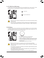
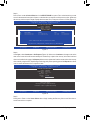
- 18 -Hardware Installation
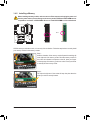
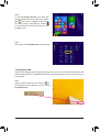
Notch
DDR4DIMM
ADDR4memorymodulehasanotch,soitcanonlytinonedirection.Followthestepsbelowtocorrectlyinstall
your memory modules in the memory sockets.
Step 1:
Note the orientation of the memory module. Spread the retaining clip
at the right end of the memory socket. Place the memory module on
thesocket.Asindicatedinthepictureontheleft,placeyourngers
on the top edge of the memory, push down on the memory and insert
it vertically into the memory socket.
Step 2:
The clip at the right end of the socket will snap into place when the
memory module is securely inserted.
1-4-2 Installing a Memory
Before installing a memory module, make sure to turn off the computer and unplug the power cord
from the power outlet to prevent damage to the memory module. DDR4 and DDR3 DIMMs are not
compatible to each other or DDR2 DIMMs. Be sure to install DDR4 DIMMs on this motherboard.

- 19 -
Hardware Installation
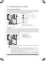
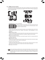
1-5 Installing an Expansion Card
Readthefollowingguidelinesbeforeyoubegintoinstallanexpansioncard:
•Make sure the motherboard supports the expansion card. Carefully read the manual that came
with your expansion card.
•Always turn off the computer and unplug the power cord from the power outlet before installing an
expansion card to prevent hardware damage.
Follow the steps below to correctly install your expansion card in the expansion slot.
1. Locateanexpansionslotthatsupportsyourcard.Removethemetalslotcoverfromthechassisbackpanel.
2. Align the card with the slot, and press down on the card until it is fully seated in the slot.
3. Make sure the metal contacts on the card are completely inserted into the slot.
4. Secure the card's metal bracket to the chassis back panel with a screw.
5. Afterinstallingallexpansioncards,replacethechassiscover(s).
6. Turn on your computer. If necessary, go to BIOS Setup to make any required BIOS changes for your expan-
sioncard(s).
7. Install the driver provided with the expansion card in your operating system.
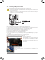
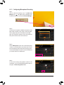
Example:InstallingandRemovingaPCIExpressGraphicsCard:
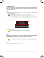
•Installing a Graphics Card:
Gently push down on the top edge of the card until
it is fully inserted into the PCI Express slot. Make
sure the card is securely seated in the slot and
does not rock.
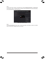
•RemovingtheCard:
Gently push back on the lever on the slot and then lift the card straight out from
the slot.
PCI Express x1 Slot
PCI Express x16 Slot

- 20 -Hardware Installation
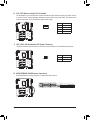
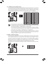
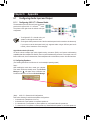
1-6 Setting up AMD CrossFire™/NVIDIA® SLI™Conguration
A. System Requirements
-Windows 10/8.1/7 operating system
-A CrossFire/SLI-supported motherboard with two PCI Express x16 slots and correct driver
-CrossFire/SLI-ready graphics cards of identical brand and chip and correct driver
(CurrentGPUsthatsupport3-Way/4-WayCrossFiretechnologyincludetheATIRadeon™ HD 3800, HD
4800,HD5800series,andAMDRadeon™ HD 6800, HD 6900, HD 7800, and HD 7900 series. Current
GPUs that support 3-Way/4-Way SLI™ technology include the NVIDIA 8800 GTX, 8800 Ultra, 9800 GTX,
GTX260,GTX280,GTX470,GTX480,GTX570,GTX580,GTX590,andGTX600series.)Forthe
latest GPU support information, please refer to the AMD/NVIDIA®website.)
-CrossFire(Note1)/SLI bridge connectors
-Apowersupplywithsufcientpowerisrecommended(Refertothemanualofyourgraphicscardsforthe
powerrequirement)(Note2)
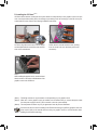
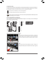
B. Connecting the Graphics Cards
Step 1:
Observe the steps in "1-5 Installing an Expansion Card" and install CrossFire/SLI graphics cards on the PCI
Expressx16slots.(Tosetupa2-Wayconguration,werecommendinstallingthegraphicscardsinthePCIEX16_1
andPCIEX16_2slots.Tosetupa3-Wayconguration,werecommendinstallingthegraphicscardsonthe
PCIEX16_1,PCIEX8_1,andPCIEX16_2slots.)
Step 2:
Insert the CrossFire (Note1)/SLI bridge connectors in the CrossFire/SLI gold edge connectors on top of the cards.
Step 3:
Plug the display cable into the graphics card on the PCIEX16_1 slot.
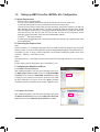
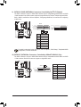
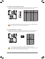
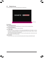
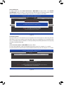
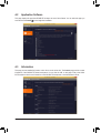
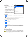
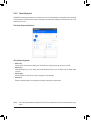
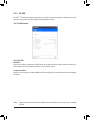
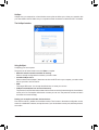
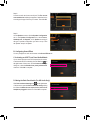
C.ConguringtheGraphicsCardDriver
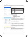
C-1. To Enable CrossFire Function
After installing the graphics card driver in the operating system, go to
the AMD Catalyst Control Center. Browse to Performance\AMD
CrossFireX™ and ensure the Enable AMD CrossFireX check box
is selected. If your system has more than two CrossFire cards, select
the GPU combination you want to use and click Apply. (Available
combinationoptionsaredependentonthenumberofgraphicscards.)
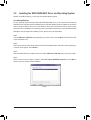
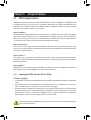
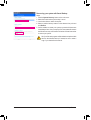
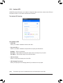
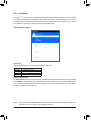
C-2. To Enable SLI Function
After installing the graphics card driver in the operating system, go to
the NVIDIA Control Panel. Browse to the CongureSLI,Surround,
Physx screen and ensure Maximize 3D performance is enabled.
Page is loading ...
Page is loading ...
Page is loading ...
Page is loading ...
Page is loading ...
Page is loading ...
Page is loading ...
Page is loading ...
Page is loading ...
Page is loading ...
Page is loading ...
Page is loading ...
Page is loading ...
Page is loading ...
Page is loading ...
Page is loading ...
Page is loading ...
Page is loading ...
Page is loading ...
Page is loading ...
Page is loading ...
Page is loading ...
Page is loading ...
Page is loading ...
Page is loading ...
Page is loading ...
Page is loading ...
Page is loading ...
Page is loading ...
Page is loading ...
Page is loading ...
Page is loading ...
Page is loading ...
Page is loading ...
Page is loading ...
Page is loading ...
Page is loading ...
Page is loading ...
Page is loading ...
Page is loading ...
Page is loading ...
Page is loading ...
Page is loading ...
Page is loading ...
Page is loading ...
Page is loading ...
Page is loading ...
Page is loading ...
Page is loading ...
Page is loading ...
Page is loading ...
Page is loading ...
Page is loading ...
Page is loading ...
Page is loading ...
Page is loading ...
Page is loading ...
Page is loading ...
Page is loading ...
Page is loading ...
Page is loading ...
Page is loading ...
Page is loading ...
Page is loading ...
Page is loading ...
Page is loading ...
Page is loading ...
Page is loading ...
Page is loading ...
Page is loading ...
Page is loading ...
Page is loading ...
Page is loading ...
Page is loading ...
Page is loading ...
Page is loading ...
Page is loading ...
Page is loading ...
Page is loading ...
Page is loading ...
Page is loading ...
Page is loading ...
Page is loading ...
Page is loading ...
Page is loading ...
Page is loading ...
Page is loading ...
Page is loading ...
Page is loading ...
Page is loading ...
Page is loading ...
Page is loading ...
Page is loading ...
Page is loading ...
Page is loading ...
Page is loading ...
Page is loading ...
Page is loading ...
Page is loading ...
Page is loading ...
Page is loading ...
Page is loading ...
Page is loading ...
Page is loading ...
Page is loading ...
Page is loading ...
Page is loading ...
Page is loading ...
Page is loading ...
Page is loading ...
Page is loading ...
Page is loading ...
-
 1
1
-
 2
2
-
 3
3
-
 4
4
-
 5
5
-
 6
6
-
 7
7
-
 8
8
-
 9
9
-
 10
10
-
 11
11
-
 12
12
-
 13
13
-
 14
14
-
 15
15
-
 16
16
-
 17
17
-
 18
18
-
 19
19
-
 20
20
-
 21
21
-
 22
22
-
 23
23
-
 24
24
-
 25
25
-
 26
26
-
 27
27
-
 28
28
-
 29
29
-
 30
30
-
 31
31
-
 32
32
-
 33
33
-
 34
34
-
 35
35
-
 36
36
-
 37
37
-
 38
38
-
 39
39
-
 40
40
-
 41
41
-
 42
42
-
 43
43
-
 44
44
-
 45
45
-
 46
46
-
 47
47
-
 48
48
-
 49
49
-
 50
50
-
 51
51
-
 52
52
-
 53
53
-
 54
54
-
 55
55
-
 56
56
-
 57
57
-
 58
58
-
 59
59
-
 60
60
-
 61
61
-
 62
62
-
 63
63
-
 64
64
-
 65
65
-
 66
66
-
 67
67
-
 68
68
-
 69
69
-
 70
70
-
 71
71
-
 72
72
-
 73
73
-
 74
74
-
 75
75
-
 76
76
-
 77
77
-
 78
78
-
 79
79
-
 80
80
-
 81
81
-
 82
82
-
 83
83
-
 84
84
-
 85
85
-
 86
86
-
 87
87
-
 88
88
-
 89
89
-
 90
90
-
 91
91
-
 92
92
-
 93
93
-
 94
94
-
 95
95
-
 96
96
-
 97
97
-
 98
98
-
 99
99
-
 100
100
-
 101
101
-
 102
102
-
 103
103
-
 104
104
-
 105
105
-
 106
106
-
 107
107
-
 108
108
-
 109
109
-
 110
110
-
 111
111
-
 112
112
-
 113
113
-
 114
114
-
 115
115
-
 116
116
-
 117
117
-
 118
118
-
 119
119
-
 120
120
-
 121
121
-
 122
122
-
 123
123
-
 124
124
-
 125
125
-
 126
126
-
 127
127
-
 128
128
-
 129
129
-
 130
130
-
 131
131
-
 132
132


Gigabyte GA-Z170X-SOC FORCE Owner's manual
- Category
- Server/workstation motherboards
- Type
- Owner's manual
Ask a question and I''ll find the answer in the document
Finding information in a document is now easier with AI
Related papers
-
Gigabyte GA-Z170X-Gaming G1 Owner's manual
-
Gigabyte X399 AORUS XTREME Owner's manual
-
Gigabyte X299 UD4 EX Owner's manual
-
Gigabyte Z370 AORUS ULTRA GAMING WIFI-OP Owner's manual
-
Gigabyte X470 AORUS GAMING 5 WIFI Owner's manual
-
Gigabyte X570 AORUS ELITE Owner's manual
-
-
-
-
Gigabyte GA-Z170-Gaming K3 Owner's manual