Gigabyte GA-970-Gaming SLI Owner's manual
- Type
- Owner's manual

To reduce the impacts on global warming, the packaging materials of this product
are recyclable and reusable. GIGABYTE works with you to protect the environment.
For more product details, please visit GIGABYTE's website.
GA-970-Gaming SLI
User's Manual
Rev. 1001
12ME-970GMS-1001R

Copyright
© 2016 GIGA-BYTE TECHNOLOGY CO., LTD. All rights reserved.
The trademarks mentioned in this manual are legally registered to their respective owners.
Disclaimer
Information in this manual is protected by copyright laws and is the property of GIGABYTE.
Changes to the specications and features in this manual may be made by GIGABYTE without prior notice.
No part of this manual may be reproduced, copied, translated, transmitted, or published in any form or
by any means without GIGABYTE's prior written permission.
For quick set-up of the product, read the Quick Installation Guide included with the product.
In order to assist in the use of this product, carefully read the User's Manual.
For product-related information, check on our website at: http://www.gigabyte.com
Identifying Your Motherboard Revision
The revision number on your motherboard looks like this: "REV: X.X." For example, "REV: 1.0" means
the revision of the motherboard is 1.0. Check your motherboard revision before updating motherboard
BIOS, drivers, or when looking for technical information.
Example:
Motherboard
GA-970-Gaming SLI
Feb. 15, 2016
Feb. 15, 2016
Motherboard
GA-970-Gaming SLI

- 3 -
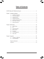
Table of Contents
GA-970-Gaming SLI Motherboard Layout ....................................................................... 4
Chapter 1 Hardware Installation .....................................................................................5
1-1 Installation Precautions .................................................................................... 5
1-2 ProductSpecications ...................................................................................... 6
1-3 Installing the CPU ............................................................................................ 9
1-4 Installing the Memory ....................................................................................... 9
1-5 Installing an Expansion Card ......................................................................... 10
1-6 Back Panel Connectors .................................................................................. 10
1-7 Internal Connectors ........................................................................................ 12
Chapter 2 BIOS Setup ..................................................................................................19
2-1 Startup Screen ............................................................................................... 20
2-2 M.I.T. .............................................................................................................. 20
2-3 System Information ........................................................................................ 24
2-4 BIOS Features ............................................................................................... 25
2-5 Peripherals ..................................................................................................... 27
2-6 Power Management ....................................................................................... 29
2-7 Save & Exit ..................................................................................................... 31
Chapter 3 Appendix ......................................................................................................32
3-1 ConguringaRAIDSet .................................................................................. 32
3-2 DriversInstallation .......................................................................................... 35
RegulatoryStatements .............................................................................................. 36
Contact Us ................................................................................................................ 40

- 4 -
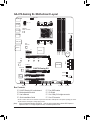
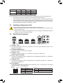
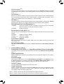
GA-970-Gaming SLI Motherboard Layout
* The box contents above are for reference only and the actual items shall depend on the product package you obtain.
The box contents are subject to change without notice.
Box Contents
5GA-970-Gaming SLI motherboard 5Four SATA cables
5Motherboard driver disk 5I/O Shield
5User's Manual 5One 2-Way SLI bridge connector
5Quick Installation Guide 5One G Connector
(Note) Duetoahardwarelimitation,thePCIEX1_1slotcanonlyaccommodateashorterPCIExpressx1
expansion card. For a longer expansion card, use other expansion slots.
KB_MS_USB
CPU_FAN
ATX
GA-970-Gaming SLI
AUDIO
SYS_FAN1
PCIEX1_1(Note)
DDR3_4
DDR3_2
ATX_12V
AMD970
AMDSB950
PCIEX1_2
CODEC
BAT
PCI1
F_USB2
B_BIOS
F_PANEL
M_BIOS
F_USB1
PCIEX16
R_USB31
CLR_CMOS
SPDIF_O
Socket AM3+
Intel®
GbE LAN
iTE®
Super I/O
R_USB
R_USB30
USB_LAN
DDR3_3
DDR3_1
PWR_FAN
F_USB30
SYS_FAN2
F_USB3
F_AUDIO
PCIEX8
PCI2
4
5
2
3
0
1
SATA3
VIA®VL805
ASMedia®
USB 3.1 Controller
M2F_20G
42F60F80F110F
TPM
COMA

Chapter 1 Hardware Installation
1-1 Installation Precautions
The motherboard contains numerous delicate electronic circuits and components which can become
damagedasaresultofelectrostaticdischarge(ESD).Priortoinstallation,carefullyreadtheuser's
manual and follow these procedures:
•Prior to installation, make sure the chassis is suitable for the motherboard.
•Prior to installation, do not remove or break motherboard S/N (Serial Number) sticker or
warranty sticker provided by your dealer. These stickers are required for warranty validation.
•Always remove the AC power by unplugging the power cord from the power outlet before
installing or removing the motherboard or other hardware components.
•When connecting hardware components to the internal connectors on the motherboard, make
sure they are connected tightly and securely.
•When handling the motherboard, avoid touching any metal leads or connectors.
•It is best to wear an electrostatic discharge (ESD) wrist strap when handling electronic
componentssuchasamotherboard,CPUormemory.IfyoudonothaveanESDwriststrap,
keepyourhandsdryandrsttouchametalobjecttoeliminatestaticelectricity.
•Prior to installing the motherboard, please have it on top of an antistatic pad or within an
electrostatic shielding container.
•Before connecting or unplugging the power supply cable from the motherboard, make sure
the power supply has been turned off.
•Before turning on the power, make sure the power supply voltage has been set according to
the local voltage standard.
•Before using the product, please verify that all cables and power connectors of your hardware
components are connected.
•To prevent damage to the motherboard, do not allow screws to come in contact with the
motherboard circuit or its components.
•Make sure there are no leftover screws or metal components placed on the motherboard or
within the computer casing.
•Donotplacethecomputersystemonanunevensurface.
•Donotplacethecomputersysteminahigh-temperatureorwetenvironment.
•Turning on the computer power during the installation process can lead to damage to system
components as well as physical harm to the user.
•If you are uncertain about any installation steps or have a problem related to the use of the
product,pleaseconsultacertiedcomputertechnician.
•If you use an adapter, extension power cable, or power strip, ensure to consult with its installation
and/or grounding instructions.
- 5 -

1-2 ProductSpecications
CPU AM3+ Socket:
- AMDAM3+FXprocessor
- AMDAM3Phenom™IIprocessor/AMDAthlon™ II processor
(Go to GIGABYTE's website for the latest CPU support list.)
HyperTransport
Bus
HyperTransport™ 3.0
Support for up to 5200 MT/s
Chipset NorthBridge:AMD970
SouthBridge:AMDSB950
Memory 4xDDR3DIMMsocketssupportingupto64GBofsystemmemory
* DuetoaWindows32-bitoperatingsystemlimitation,whenmorethan4GBofphysical
memory is installed, the actual memory size displayed will be less than the size of
the physical memory installed.
Dualchannelmemoryarchitecture
SupportforDDR32000(O.C.)/1866/1600/1333/1066MHzmemorymodules
* TosupportaDDR31866MHz(andabove)memory,youmustinstallanAM3+CPU
rst.
SupportforExtremeMemoryProle(XMP)memorymodules
(Go to GIGABYTE's website for the latest supported memory speeds and memory
modules.)
Audio Realtek® ALC1150 codec
HighDenitionAudio
2/4/5.1/7.1-channel
SupportforS/PDIFOut
LAN Intel® GbE LAN chip (10/100/1000 Mbit)
Expansion Slots 1xPCIExpressx16slot,runningatx16(PCIEX16)
* For optimum performance, if only one PCI Express graphics card is to be installed,
besuretoinstallitinthePCIEX16slot.
1xPCIExpressx16slot,runningatx8(PCIEX8)
* ThePCIEX8slotsharesbandwidthwiththePCIEX16slot.WhenthePCIEX8slotis
populated,thePCIEX16slotwilloperateatuptox8mode.
2 x PCI Express x1 slots
(All of the PCI Express slots conform to PCI Express 2.0 standard.)
2 x PCI slots
Multi-Graphics
Technology Supportfor2-WayAMDCrossFire™/2-Way NVIDIA® SLI™ technology
Storage Interface South Bridge:
- 1xM.2connector(Socket3,Mkey,type2242/2260/2280/22110SATA
andPCIex4/x2/x1SSDsupport)
- 6 x SATA 6Gb/s connectors
- SupportforRAID0,RAID1,RAID5,RAID10,andJBOD
* Referto"1-7InternalConnectors,"forthesupportedcongurationswiththeM.2and
SATA connectors.
- 6 -

USB South Bridge:
- 12 x USB 2.0/1.1 ports (6 ports on the back panel, 6 ports available through
the internal USB headers)
VIA®VL805chip:
- 4 x USB 3.0/2.0 ports (2 ports on the back panel, 2 ports available through
the internal USB header)
ASMedia® USB 3.1 Controller:
- 2 x USB 3.1 Type-A ports (red) on the back panel
Internal
Connectors
1x24-pinATXmainpowerconnector
1x8-pinATX12Vpowerconnector
1 x M.2 Socket 3 connector
6 x SATA 6Gb/s connectors
1 x CPU fan header
2 x system fan headers
1 x power fan header
1 x front panel header
1 x front panel audio header
1xS/PDIFOutheader
1 x USB 3.0/2.0 header
3 x USB 2.0/1.1 headers
1 x serial port header
1 x Clear CMOS jumper
1 x Trusted Platform Module (TPM) header
Back Panel
Connectors
1 x PS/2 keyboard/mouse port
2 x USB 3.1 Type-A ports (red)
2 x USB 3.0/2.0 ports
6 x USB 2.0/1.1 ports
1xRJ-45port
1xopticalS/PDIFOutconnector
5xaudio jacks (Center/Subwoofer Speaker Out, RearSpeaker Out, Line In,
Line Out, Mic In)
I/O Controller iTE® I/O Controller Chip
Hardware
Monitor
System voltage detection
CPU/System temperature detection
CPU/System/Power fan speed detection
CPU overheating warning
CPU/System/Power fan fail warning
CPU/System fan speed control
* Whether the fan speed control function is supported will depend on the cooler you
install.
- 7 -

BIOS 2x32Mbitash
Use of licensed AMI UEFI BIOS
SupportforDualBIOS™
PnP1.0a,DMI2.7,WfM2.0,SMBIOS2.7,ACPI5.0
Unique Features Support for APP Center
* Available applications in APP Center may vary by motherboard model. Supported
functionsofeachapplicationmayalsovarydependingonmotherboardspecications.
- @BIOS
- AmbientLED
- Cloud Station
- EasyTune
- Game Controller
- Smart TimeLock
- SmartRecovery2
- SystemInformationViewer
- USB Blocker
Support for Q-Flash
Support for ON/OFF Charge
Support for Smart Switch
SupportforXpressInstall
Bundled
Software
Norton® Internet Security (OEM version)
cFosSpeed
Operating
System SupportforWindows10/8.1/732-bit/64-bit
Form Factor ATXFormFactor;30.5cmx24.4cm
*GIGABYTEreservestherighttomakeanychangestotheproductspecicationsandproduct-relatedinformationwithout
prior notice.
Please visit GIGABYTE's website
for support lists of CPU, memory
modules,SSDs,andM.2devices.
Please visit the Support\Utility List
page on GIGABYTE's website to
download the latest version of apps.
-8-

Please visit GIGABYTE's website for details on hardware installation.
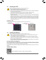
1-3 Installing the CPU
ReadthefollowingguidelinesbeforeyoubegintoinstalltheCPU:
•Make sure that the motherboard supports the CPU.
(Go to GIGABYTE's website for the latest CPU support list.)
•Always turn off the computer and unplug the power cord from the power outlet before installing the
CPU to prevent hardware damage.
•Locate the pin one of the CPU. The CPU cannot be inserted if oriented incorrectly.
•Apply an even and thin layer of thermal grease on the surface of the CPU.
•DonotturnonthecomputeriftheCPUcoolerisnotinstalled,otherwiseoverheatinganddamage
of the CPU may occur.
•SettheCPUhostfrequencyinaccordancewiththeCPUspecications.Itisnotrecommended
thatthesystembusfrequencybesetbeyondhardwarespecicationssinceitdoesnotmeetthe
standard requirements for the peripherals. If you wish to set the frequency beyond the standard
specications,pleasedosoaccordingtoyourhardwarespecicationsincludingtheCPU,graphics
card, memory, hard drive, etc.
Installing the CPU
Locate the pin one (denoted by a small triangle) of the CPU socket and the CPU.
1-4 Installing the Memory
DualChannelMemoryConguration
Thismotherboardprovidesfour DDR3 memory sockets and supports Dual Channel Technology.After the
memoryisinstalled,theBIOSwillautomaticallydetectthespecicationsandcapacityofthememory.Enabling
DualChannelmemorymodewilldoubletheoriginalmemorybandwidth.
ThefourDDR3memorysocketsaredividedintotwochannelsandeachchannelhastwomemorysocketsas
following:
ChannelA:DDR3_2,DDR3_4
ChannelB:DDR3_1,DDR3_3
Readthefollowingguidelinesbeforeyoubegintoinstallthememory:
•Make sure that the motherboard supports the memory. It is recommended that memory of the
same capacity, brand, speed, and chips be used.
(Go to GIGABYTE's website for the latest supported memory speeds and memory modules.)
•Always turn off the computer and unplug the power cord from the power outlet before installing the
memory to prevent hardware damage.
•Memory modules have a foolproof design. A memory module can be installed in only one direction.
If you are unable to insert the memory, switch the direction.
AM3+ Socket
A Small Triangle
MarkingDenotesPin
One of the Socket AM3+/AM3 CPU
A Small Triangle
MarkingDenotesCPU
Pin One
- 9 -

DuetoCPUlimitations,readthefollowingguidelinesbeforeinstallingthememoryinDualChannelmode.
1. DualChannelmodecannotbeenabledifonlyonememorymoduleisinstalled.
2. WhenenablingDualChannelmodewithtwoorfourmemorymodules,itisrecommendedthatmemory
of the same capacity, brand, speed, and chips be used and installed in the same colored sockets. For
optimumperformance,whenenablingDualChannelmodewithtwomemorymodules,werecommend
thatyouinstallthemintheDDR3_1andDDR3_2sockets.
1-5 Installing an Expansion Card
Readthefollowingguidelinesbeforeyoubegintoinstallanexpansioncard:
•Make sure the motherboard supports the expansion card. Carefully read the manual that came
with your expansion card.
•Always turn off the computer and unplug the power cord from the power outlet before installing an
expansion card to prevent hardware damage.
1-6 Back Panel Connectors
USB 2.0/1.1 Port
TheUSBportsupportstheUSB2.0/1.1specication.YoucanconnectaUSBDACtothisportoruse
this port for USB devices.
PS/2 Keyboard/Mouse Port
Use this port to connect a PS/2 mouse or keyboard.
USB 2.0/1.1 Port
TheUSBportsupportstheUSB2.0/1.1specication.UsethisportforUSBdevices.
USB 3.1 Type-A Port (Red)
TheUSB3.1portsupportstheUSB3.1specicationandiscompatibletotheUSB3.0/2.0/1.1specication.
Use this port for USB devices.
USB 3.0/2.0 Port
TheUSB3.0portsupportstheUSB3.0specicationandiscompatibletotheUSB2.0/1.1specication.
Use this port for USB devices.
RJ-45 LAN Port
The Gigabit Ethernet LAN port provides Internet connection at up to 1 Gbps data rate. The following
describesthestatesoftheLANportLEDs.
DualChannelMemoryCongurationsTable
DDR3_4 DDR3_2 DDR3_3 DDR3_1
2 Modules - - DS/SS - - DS/SS
DS/SS - - DS/SS - -
4 Modules DS/SS DS/SS DS/SS DS/SS
(SS=Single-Sided,DS=Double-Sided,"--"=NoMemory)
ActivityLED
Connection/
SpeedLED
LAN Port
ActivityLED:
Connection/SpeedLED:
State Description
Orange 1 Gbps data rate
Green 100 Mbps data rate
Off 10 Mbps data rate
State Description
Blinking Datatransmissionorreceivingisoccurring
On No data transmission or receiving is occurring
- 10 -

Center/Subwoofer Speaker Out
Usethisaudiojacktoconnectcenter/subwooferspeakersina5.1/7.1-channelaudioconguration.
Rear Speaker Out
Thisjackcanbeusedtoconnectrearspeakersina4/5.1/7.1-channelaudioconguration.
Optical S/PDIF Out Connector
This connector provides digital audio out to an external audio system that supports digital optical audio.
Before using this feature, ensure that your audio system provides an optical digital audio in connector.
Line In
The line in jack. Use this audio jack for line in devices such as an optical drive, walkman, etc.
Line Out
The line out jack. This jack supports audio amplifying function. For better sound quality, it is recommended
that you connect your headphone/speaker to this jack (actual effects may vary by the device being used).
Use this audio jack for a headphone or 2-channel speaker. This jack can be used to connect front speakers
ina4/5.1/7.1-channelaudioconguration.
Mic In
The Mic in jack.
If you want to install a Side Speaker, you need to retask either the Line in or Mic in jack to be Side
Speaker out through the audio driver. Please visit GIGABYTE's website for more software information.
•Whenremovingthecableconnectedtoabackpanelconnector,rstremovethecablefromyour
device and then remove it from the motherboard.
•Whenremovingthecable,pullitstraightoutfromtheconnector.Donotrockitsidetosideto
prevent an electrical short inside the cable connector.
- 11 -

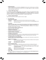
1-7 Internal Connectors
Readthefollowingguidelinesbeforeconnectingexternaldevices:
•First make sure your devices are compliant with the connectors you wish to connect.
•Before installing the devices, be sure to turn off the devices and your computer. Unplug the power
cord from the power outlet to prevent damage to the devices.
•After installing the device and before turning on the computer, make sure the device cable has
been securely attached to the connector on the motherboard.
1) ATX_12V
2) ATX
3) CPU_FAN
4) SYS_FAN1/2
5) PWR_FAN
6) SATA3 0/1/2/3/4/5
7) M2F_ 20G
8) F_PANEL
9) F_AUDIO
10) SPDIF_O
11) F_USB30
12) F_USB1/F_USB2/F_USB3
13) COMA
14) TPM
15) BAT
16) CLR_CMOS
1
5
2
15
3
6
4
814109 11
7
16
12 413
- 12 -

DEBUG
PORT
G.QBOFM
131
2412
ATX
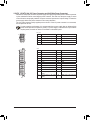
1/2) ATX_12V/ATX (2x4 12V Power Connector and 2x12 Main Power Connector)
With the use of the power connector, the power supply can supply enough stable power to all the components
onthemotherboard.Beforeconnectingthepowerconnector,rstmakesurethepowersupplyisturned
off and all devices are properly installed. The power connector possesses a foolproof design. Connect the
power supply cable to the power connector in the correct orientation.
The12VpowerconnectormainlysuppliespowertotheCPU.Ifthe12Vpowerconnectorisnotconnected,
the computer will not start.
To meet expansion requirements, it is recommended that a power supply that can withstand high
power consumption be used (500W or greater). If a power supply is used that does not provide the
required power, the result can lead to an unstable or unbootable system.
ATX:
Pin No. Denition Pin No. Denition
13.3V 13 3.3V
23.3V 14 -12V
3GND 15 GND
4+5V 16 PS_ON(softOn/Off)
5GND 17 GND
6+5V 18 GND
7GND 19 GND
8Power Good 20 NC
95VSB(standby+5V) 21 +5V
10 +12V 22 +5V
11 +12V(Onlyfor 2x12-pin
ATX)
23 +5V(Onlyfor2x12-pinATX)
12 3.3V(Onlyfor 2x12-pin
ATX)
24 GND(Onlyfor2x12-pinATX)
ATX_12V:
Pin No. Denition Pin No. Denition
1GND(Onlyfor2x4-pin12V) 5+12V(Onlyfor2x4-pin12V)
2GND(Onlyfor2x4-pin12V) 6+12V(Onlyfor2x4-pin12V)
3GND 7+12V
4GND 8 +12V
DEBUG
PORT
G.QBOFM
ATX_12V
5
8
1
4
- 13 -

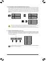
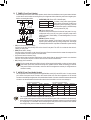
6) SATA3 0/1/2/3/4/5 (SATA 6Gb/s Connectors)
The SATA connectors conform to SATA 6Gb/s standard and are compatible with SATA 3Gb/s and SATA
1.5Gb/sstandard.EachSATAconnectorsupportsasingleSATAdevice.TheAMDSouthBridgesupports
RAID0,RAID1,RAID5,RAID10,andJBOD.RefertoChapter3,"ConguringaRAIDSet,"forinstructions
onconguringaRAIDarray.
Pin No. Denition
1GND
2TXP
3TXN
4GND
5RXN
6RXP
7GND
Toenablehot-pluggingfortheSATAports,refertoChapter2,"BIOSSetup,""Peripherals\SBSATA
Conguration,"formoreinformation.
SYS_FAN2/PWR_FAN:
Pin No. Denition
1GND
2+12V
3 Sense
•Be sure to connect fan cables to the fan headers to prevent your CPU and system from
overheating. Overheating may result in damage to the CPU or the system may hang.
•Thesefanheadersarenotcongurationjumperblocks.Donotplaceajumpercapontheheaders.
3/4/5) CPU_FAN/SYS_FAN1/SYS_FAN2/PWR_FAN (Fan Headers)
Themotherboardhasa4-pinCPUfanheader(CPU_FAN),a4-pin(SYS_FAN1)anda3-pin(SYS_FAN2)
systemfanheaders,anda3-pinpowerfanheader(PWR_FAN).Mostfanheaderspossessafoolproof
insertion design. When connecting a fan cable, be sure to connect it in the correct orientation (the black
connector wire is the ground wire). The speed control function requires the use of a fan with fan speed
control design. For optimum heat dissipation, it is recommended that a system fan be installed inside the
chassis.
CPU_FAN
DEBUG
PORT
G.QBOFM
1
CPU_FAN:
Pin No. Denition
1GND
2+12V
3 Sense
4 Speed Control
SYS_FAN1:
Pin No. Denition
1GND
2 Speed Control
3 Sense
4VCC
1
PWR_FAN
DEBUG
PORT
G.QBOFM
1
SYS_FAN1
SYS_FAN2
1
1
1
DEBUG
PORT
G.QBOFM
DEBUG
PORT
G.QBOFM
DEBUG
PORT
G.QBOFM
7
7
0
1
2
3
4
5
SATA3
- 14 -

SelecttheproperholefortheM.2SSDtobeinstalledandrefastenthescrewandnut.
7) M2F_20G (M.2 Socket 3 Connector)
TheM.2connectorsupportsM.2SATASSDsandM.2PCIeSSDs.ItcansupportSATARAIDconguration
throughtheAMDSouthBridge.PleasenotethatanM.2PCIeSSDcannotbeusedtocreateaRAIDset
withSATAdrive(s).RefertoChapter3,"ConguringaRAIDSet,"forinstructionsonconguringaRAID
array.
FollowthestepsbelowtocorrectlyinstallanM.2SSDintheM.2connector.
Step 1:
Use a screw driver to unfasten the screw and nut from the motherboard. Locate the proper mounting hole
fortheM.2SSDtobeinstalledandthenscrewthenutrst.
Step 2:
SlidetheM.2SSDintotheconnectoratanangle.
Step 3:
PresstheM.2SSDdownandthensecureitwiththescrew.
(Note) PleasenotethatanM.2PCIeSSDcannotbeusedtocreateaRAIDsetwithSATAdrive(s).
F_USB30 F_U
B_
F_ F_
_
B
BS_
B
SB_
B
_S
S_
_
B
_U
_
B
S
123
123
123
123
1
1
1
1
BSS
S
_S
SSU
1 2 3
S3 BSSS U
__ 3
F_USB3F
S _
S _
S _
SF
B_
F
_0
S
S
_0F
_F
_
_
__B
80F 60F 42F
110F
- 15 -
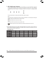
WheninstallingdifferenttypesofM.2SSDs(includingSATASSDs,PCIex4SSDs,andPCIex2SSDs),be
suretorefertothesupportedcongurationsinthetablesbelowaccordingtotheoperatingmodeofyour
SATAcontroller(AHCImodeorRAIDmode).
•AHCI/RAID mode:
SATA3_0 SATA3_1 SATA3_2 SATA3_3 SATA3_4 SATA3_5
M.2SATASSD aaaaar
M.2 PCIe x4
SSD (Note) a a a a a a
M.2 PCIe x2
SSD (Note) a a a a a a
NoM.2SSDs
Installed a a a a a a
a: Supported, r: Not supported.
Connector
TypeofSSD

The front panel design may differ by chassis. A front panel module mainly consists of power switch,
resetswitch,powerLED,harddriveactivityLED,speakerandetc.Whenconnectingyourchassis
front panel module to this header, make sure the wire assignments and the pin assignments are
matched correctly.
8) F_PANEL (Front Panel Header)
Connect the power switch, reset switch, speaker, chassis intrusion switch/sensor and system status indicator
on the chassis to this header according to the pin assignments below. Note the positive and negative pins
before connecting the cables.
System Status LED
S0 On
S3/S4/S5 Off
•PW(PowerSwitch,Red):
Connects to the power switch on the chassis front panel. You may
congurethewaytoturnoffyoursystemusingthepowerswitch
(refertoChapter2,"BIOSSetup,""PowerManagement,"formore
information).
•SPEAK (Speaker, Orange):
Connects to the speaker on the chassis front panel. The system
reports system startup status by issuing a beep code. One single
short beep will be heard if no problem is detected at system startup.
•PLED/PWR_LED (PowerLED,Yellow/Purple):
Connects to the power status indicator
onthechassisfrontpanel.TheLEDison
whenthesystemisoperating.TheLED
is off when the system is in S3/S4 sleep
state or powered off (S5).
•HD (HardDriveActivityLED,Blue):
ConnectstotheharddriveactivityLEDonthechassisfrontpanel.TheLEDisonwhentheharddriveis
reading or writing data.
•RES (ResetSwitch,Green):
Connects to the reset switch on the chassis front panel. Press the reset switch to restart the computer if the
computer freezes and fails to perform a normal restart.
•CI (Chassis Intrusion Header, Gray):
Connects to the chassis intrusion switch/sensor on the chassis that can detect if the chassis cover has been
removed. This function requires a chassis with a chassis intrusion switch/sensor.
•NC (Orange): No Connection.
•ThefrontpanelaudioheadersupportsHDaudiobydefault.
•Audio signals will be present on both of the front and back panel audio connections simultaneously.
•Some chassis provide a front panel audio module that has separated connectors on each wire instead
of a single plug. For information about connecting the front panel audio module that has different
wire assignments, please contact the chassis manufacturer.
9) F_AUDIO (Front Panel Audio Header)
ThefrontpanelaudioheadersupportsIntelHighDenitionaudio(HD)andAC'97audio.Youmayconnect
your chassis front panel audio module to this header. Make sure the wire assignments of the module
connector match the pin assignments of the motherboard header. Incorrect connection between the module
connector and the motherboard header will make the device unable to work or even damage it.
F_USB30 F_U
B_
F_ F_
_
B
BS_
B
SB_
B
_S
S_
_
B
_U
_
B
S
123
123
123
123
1
1
1
1
BSS
S
_S
SSU
1 2 3
S3 BSSS U
__ 3
F_USB3F
S _
S _
S _
SF
B_
F
_0
S
S
_0F
_F
_
_
__B
9 1
10 2
ForHDFrontPanelAudio:
Pin No. Denition Pin No. Denition
1MIC2_L 6 Sense
2GND 7FAUDIO_JD
3MIC2_R 8 No Pin
4-ACZ_DET 9LINE2_L
5LINE2_R 10 Sense
For AC'97 Front Panel Audio:
Pin No. Denition Pin No. Denition
1 MIC 6 NC
2GND 7 NC
3 MIC Power 8No Pin
4 NC 9 Line Out (L)
5LineOut(R) 10 NC
PowerLED
DEBUG
PORT
G.QBOFM
1
2
19
20
CI-
CI+
PWR_LED-
PWR_LED+
PLED-
PW-
SPEAK+
SPEAK-
PLED+
PW+
PowerLED
HD-
RES+
HD+
RES-
HardDrive
ActivityLED
Reset
Switch Chassis Intrusion
Header
Power Switch Speaker
PWR_LED-
NC
NC
- 16 -

10) SPDIF_O (S/PDIF Out Header)
ThisheadersupportsdigitalS/PDIFOutandconnectsaS/PDIFdigitalaudiocable(providedbyexpansion
cards) for digital audio output from your motherboard to certain expansion cards like graphics cards and
soundcards.Forexample,somegraphicscardsmayrequireyoutouseaS/PDIFdigitalaudiocablefor
digitalaudiooutputfromyourmotherboardtoyourgraphicscardifyouwishtoconnectanHDMIdisplay
tothegraphicscardandhavedigitalaudiooutputfromtheHDMIdisplayatthesametime.Forinformation
aboutconnectingtheS/PDIFdigitalaudiocable,carefullyreadthemanualforyourexpansioncard.
Pin No. Denition
1SPDIFO
2GND
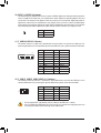
Pin No. Denition Pin No. Denition
1VBUS 11 D2+
2SSRX1- 12 D2-
3SSRX1+ 13 GND
4GND 14 SSTX2+
5SSTX1- 15 SSTX2-
6SSTX1+ 16 GND
7GND 17 SSRX2+
8 D1- 18 SSRX2-
9D1+ 19 VBUS
10 NC 20 No Pin
11) F_USB30 (USB 3.0/2.0 Header)
Theheader conforms to USB 3.0/2.0 specication andeach header can provide two USB ports.For
purchasingtheoptional3.5"frontpanelthatprovidestwoUSB3.0/2.0ports,pleasecontactthelocaldealer.
1
F_USB30 F_U
B_
F_ F_
_
B
BS_
B
SB_
B
_S
S_
_
B
_U
_
B
S
123
123
123
123
1
1
1
1
BSS
S
_S
SSU
1 2 3
S3 BSSS U
__ 3
F_USB3F
S _
S _
S _
SF
B_
F
_0
S
S
_0F
_F
_
_
__B
10
20
1
11
12) F_USB1/F_USB2/F_USB3 (USB 2.0/1.1 Headers)
TheheadersconformtoUSB2.0/1.1specication.EachUSBheadercanprovidetwoUSBportsviaan
optional USB bracket. For purchasing the optional USB bracket, please contact the local dealer.
Pin No. Denition Pin No. Denition
1Power(5V) 6USBDY+
2Power(5V) 7GND
3USBDX- 8 GND
4USBDY- 9 No Pin
5USBDX+ 10 NC
•DonotplugtheIEEE1394bracket(2x5-pin)cableintotheUSB2.0/1.1header.
•Prior to installing the USB bracket, be sure to turn off your computer and unplug the power cord
from the power outlet to prevent damage to the USB bracket.
DEBUG
PORT
G.QBOFM
10
9
2
1
- 17 -

13) COMA (Serial Port Header)
The COM header can provide one serial port via an optional COM port cable. For purchasing the optional
COM port cable, please contact the local dealer.
Pin No. Denition Pin No. Denition
1NDCD- 6NDSR-
2NSIN 7NRTS-
3NSOUT 8NCTS-
4NDTR- 9NRI-
5GND 10 No Pin
10
9
2
1
15) BAT (Battery)
Thebatteryprovidespowertokeepthevalues(suchasBIOScongurations,date,andtimeinformation)
intheCMOSwhenthecomputeristurnedoff.Replacethebatterywhenthebatteryvoltagedropstoalow
level, or the CMOS values may not be accurate or may be lost.
You may clear the CMOS values by removing the battery:
1. Turn off your computer and unplug the power cord.
2. Gently remove the battery from the battery holder and wait for one minute. (Or use
a metal object like a screwdriver to touch the positive and negative terminals of the
battery holder, making them short for 5 seconds.)
3. Replacethebattery.
4. Plug in the power cord and restart your computer.
•Always turn off your computer and unplug the power cord before replacing the battery.
•Replacethebatterywithanequivalentone.Dangerofexplosionifthebatteryisreplacedwith
an incorrect model.
•Contact the place of purchase or local dealer if you are not able to replace the battery by yourself
or uncertain about the battery model.
•When installing the battery, note the orientation of the positive side (+) and the negative side (-)
of the battery (the positive side should face up).
•Used batteries must be handled in accordance with local environmental regulations.
20
19
2
1
F_USB30 F_U
B_
F_ F_
_
B
BS_
B
SB_
B
_S
S_
_
B
_U
_
B
S
123
123
123
123
1
1
1
1
BSS
S
_S
SSU
1 2 3
S3 BSSS U
__ 3
F_USB3F
S _
S _
S _
SF
B_
F
_0
S
S
_0F
_F
_
_
__B
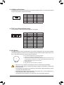
14) TPM (Trusted Platform Module Header)
You may connect a TPM (Trusted Platform Module) to this header.
Pin No. Denition Pin No. Denition
1 LCLK 11 LAD0
2GND 12 GND
3LFRAME 13 NC
4 No Pin 14 NC
5LRESET 15 SB3V
6 NC 16 SERIRQ
7LAD3 17 GND
8 LAD2 18 NC
9VCC3 19 NC
10 LAD1 20 SUSCLK
-18-

16) CLR_CMOS (Clear CMOS Jumper)
UsethisjumpertocleartheBIOScongurationandresettheCMOSvaluestofactorydefaults.Toclear
the CMOS values, use a metal object like a screwdriver to touch the two pins for a few seconds.
•Always turn off your computer and unplug the power cord from the power outlet before clearing
the CMOS values.
•Aftersystemrestart,gotoBIOSSetuptoloadfactorydefaults(selectLoadOptimizedDefaults)or
manuallyconguretheBIOSsettings(refertoChapter2,"BIOSSetup,"forBIOScongurations).
Open: Normal
Short:ClearCMOSValues
Chapter 2 BIOS Setup
BIOS (Basic Input and Output System) records hardware parameters of the system in the CMOS on the
motherboard. Its major functions include conducting the Power-On Self-Test (POST) during system startup,
saving system parameters and loading operating system, etc. BIOS includes a BIOS Setup program that allows
theusertomodifybasicsystemcongurationsettingsortoactivatecertainsystemfeatures.
When the power is turned off, the battery on the motherboard supplies the necessary power to the CMOS to
keepthecongurationvaluesintheCMOS.
ToaccesstheBIOSSetupprogram,pressthe<Delete>keyduringthePOSTwhenthepoweristurnedon.
To upgrade the BIOS, use either the GIGABYTE Q-Flash or @BIOS utility.
•Q-Flash allows the user to quickly and easily upgrade or back up BIOS without entering the operating system.
•@BIOS is a Windows-based utility that searches and downloads the latest version of BIOS from the Internet
and updates the BIOS.
•BecauseBIOSashingispotentiallyrisky,ifyoudonotencounterproblemsusingthecurrentversionofBIOS,
itisrecommendedthatyounotashtheBIOS.ToashtheBIOS,doitwithcaution.InadequateBIOSashing
may result in system malfunction.
•It is recommended that you not alter the default settings (unless you need to) to prevent system instability or other
unexpected results. Inadequately altering the settings may result in system's failure to boot. If this occurs, try to
cleartheCMOSvaluesandresettheboardtodefaultvalues.(Refertothe"LoadOptimizedDefaults"sectionin
this chapter or introductions of the battery/clear CMOS jumper in Chapter 1 for how to clear the CMOS values.)
- 19 -

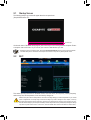
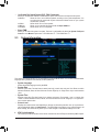
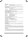
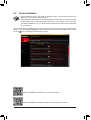
2-1 Startup Screen
The following startup Logo screen will appear when the computer boots.
(SampleBIOSVersion:E7)
Function Keys
•When the system is not stable as usual, select the Load Optimized Defaults item to set your system to its defaults.
•The BIOS Setup menus described in this chapter are for reference only and may differ by BIOS version.
OnthemainmenuoftheBIOSSetupprogram,pressarrowkeystomoveamongtheitemsandpress<Enter>
to accept or enter a sub-menu. Or you can use your mouse to select the item you want.
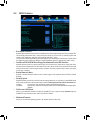
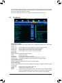
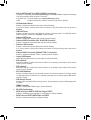
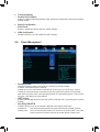
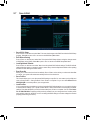
2-2 M.I.T.
This section provides information on the BIOS version, CPU base clock, CPU frequency, memory frequency,
totalmemorysize,CPUtemperature,Vcoreandmemoryvoltage,etc.
Whether the system will work stably with the overclock/overvoltage settings you made is dependent on your overall
systemcongurations.Incorrectlydoingoverclock/overvoltagemayresultindamagetoCPU,chipset,ormemory
and reduce the useful life of these components. This page is for advanced users only and we recommend you not to
alter the default settings to prevent system instability or other unexpected results. (Inadequately altering the settings
may result in system's failure to boot. If this occurs, clear the CMOS values and reset the board to default values.)
- 20 -
Page is loading ...
Page is loading ...
Page is loading ...
Page is loading ...
Page is loading ...
Page is loading ...
Page is loading ...
Page is loading ...
Page is loading ...
Page is loading ...
Page is loading ...
Page is loading ...
Page is loading ...
Page is loading ...
Page is loading ...
Page is loading ...
Page is loading ...
Page is loading ...
Page is loading ...
Page is loading ...
-
 1
1
-
 2
2
-
 3
3
-
 4
4
-
 5
5
-
 6
6
-
 7
7
-
 8
8
-
 9
9
-
 10
10
-
 11
11
-
 12
12
-
 13
13
-
 14
14
-
 15
15
-
 16
16
-
 17
17
-
 18
18
-
 19
19
-
 20
20
-
 21
21
-
 22
22
-
 23
23
-
 24
24
-
 25
25
-
 26
26
-
 27
27
-
 28
28
-
 29
29
-
 30
30
-
 31
31
-
 32
32
-
 33
33
-
 34
34
-
 35
35
-
 36
36
-
 37
37
-
 38
38
-
 39
39
-
 40
40


Gigabyte GA-970-Gaming SLI Owner's manual
- Type
- Owner's manual
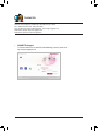
Ask a question and I''ll find the answer in the document
Finding information in a document is now easier with AI
Related papers
-
Gigabyte GA-970-Gaming Owner's manual
-
-
Gigabyte GA-B150N-GSM Owner's manual
-
-
-
Gigabyte GA-990XA-UD3 User manual
-
Gigabyte GA-Z87MX-D3H Owner's manual
-
-
Gigabyte GA-970A-DS3P User manual
-