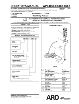
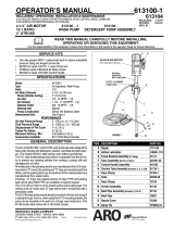
Page is loading ...

INGERSOLL RAND COMPANY LTD
209 NORTH MAIN STREET – BRYAN, OHIO 43506
(800) 495-0276 y FAX (800) 892-6276 © 2010 CCN 15337322
www.ingersollrandproducts.com
OPERATOR’S MANUAL DC0450L5XXXXXXXX
INCLUDING: OPERATION, INSTALLATION AND MAINTENANCE.
INCLUDE MANUALS: AF0450XXXXXXX-XX-X Pump (97999- 1052), & S-632 General Information (pn
97999-624).
RELEASED: 2-15-10
(REV. 01)
DC0450L5XXXXXXXX
BASIC GREASE PUMP PACKAGE
READ THIS MANUAL CAREFULLY BEFORE INSTALLING,
OPERATING OR SERVICING THIS EQUIPMENT.
It is the responsibility of the employer to place this information in the hands of the operator. Keep for future reference.
4 1/4” AIR MOTOR
50:1 RATIO
4 STROKE
SERVICE KITS
Use only genuine ARO® replacement parts to assure compat-
ible pressure rating and longest service life.
637489 for repair of air motor section.
637485 for packing.
MODEL DESCRIPTION CHART
y
y
y
Figure 1
Air Motor Size
4 - 4 1/4”
Pump Ratio
50 - 50:1
Check Type / Wetted Materials
L - Primer Piston (inlet) / Ball (outlet),
Carbon Steel, for Grease Pump
Lower Pump End Options
Refer to pump model operator’s manual
Container Suitability
55 Gallon (400 lbs)
Package
DC - Drum Cover
Follower Assembly
00 - None
GENERAL DESCRIPTION
This model is desgned for chassis lubrication, The model cov-
ered by Itis manual includes an outlet swel, material supply
noses and airline kibricotor Material dispensing accessories
and supply lines and ttings must be capable of withstand-
ing pressures developed by pump.
The ARO 50:1 ratio basic pump assembly consists at 4 1/4” air
motor, and ball-check lower pump end.
AIR AND LUBE REQUIREMENTS
WARNING DO NOT EXCEED MAXIMUM INLET AIR
PRESSURE OF 150 PSI (10 BAR). OPERATING PUMP
AT HIGHER PRESSURE MAY CAUSE PUMP DAMAGE
AND/OR PERSONAL INJURY AND/OR PROPERTY
DAMAGE.
Excessive air pressure will shorten the life of the pump.
For maximum operating e ciency. The fol lowing air sup-
ply speci cation should be maintained to this pump.
AIR PRESSURE — up to 150 PS.I (10 bar)
AIR FILTRATION — 50 mIcron
LUBRICATED AIR SUPPLY
AIR INLET SIZE — 1/2’ NPTF
Filtered and oiled air will allow the pump to operate more
efficiently and yield a longer life to operating parts and
mechanisms.
Lack of or an excessive amount of lubrication will a ect
the performance and life of this pump. Use only recom-
mended lubricants.
DAILY Fill aIr line lubricator reservoir with a good grade
of S.A.E. NO. 90W non-detergent gear oil, adjust to 1 to 2
drops per minute.
y
y
y
y
y
y
y
y
y
Package Option
0 - None
1 - Integrated ball valve regulator on pump
DC 04 50 L 5 XXXXX XX X

Page 2 of 4 DC0450L5XXXXXXXX (en)
OPERATING INSTRUCTIONS
Be sure material hose, lines and other components
are able to withstand pressure developed by
pumps.
When a pump is installed and ready to operate: Connect air
supply to air motor inlet. Regulate air pressure from p.s.i.g
(2.07 bar) to 50 p.s.i.g (3.4 bar). Allow pump to cycle slowly
to prime with material and bleed all air from system
.
1.
MAINTENANCE
If the pump is to be inoperative for a lengthly period of time (a
few hours), disconnect air and relieve all pressure from system.
Periodically ush pump with a solvent that is compatible
with material being pumped.
Disassembly should be done on a clean work bench with
clean cloths to keep parts clean.
If replacement parts are necessary, consult drawings contain-
ing parts for identi cation.
Before reassembling, lubricate parts where required. When
assembling “0” rings or parts adjacent to “0” rings, care must
be exercised to prevent damage to “0” rings and “0” ring
groove surfaces.
INSTALLATION
Remove pump from packaging material and install and secure
pump to cover, bung or other mounting accessory as ordered.
See gure 2 for view of complete assembly.
Before connecting pump, rst blow out material line
with air.
After the system is hooked up, pump a small amount
of material through the line. This material should be
discarded. (Do this to clear any foreign material out of
lines).
1.
2.
TROUBLE-SHOOTING
Should pump operate, but dispense little or no material,
check for:
lnadequote supply of material or possible malfunction-
ing of 65872 Foot Valve which would prevent material
from feeding Into suction tube.
lmproper feeding of lubncant into pump. This condi-
tion Is known as ‘channeling” and is often indicated by
light-colored frothly grease coming from control handle.
Also, grease in container will not be level, but will cling to
side of container and slope down to suction tube inlet. It
usually occurs at cool temperatures and can be corrected
by using follower plate.
Dirt or foreign matter in 65872 Foot Valve or other cause
which may be preventing it from closing on downstroke
of piston.
If unit should fail to operate, the following procedure will be
helpful in determining the cause:
Check air pressure at pump to insure air line is not ob-
structed and air is being supplied to pump.
Insufticient air is not the trouble, disconnect 310 Speed
Coupler at pump and then detach Hose and Gun at 2453
Check Valve, REMOVE SLOWLY AS PRESSURE MAY BE
BUILT UP IN PUMP. Hold rag at this point and apply air
to pump. If pump now operates, there Is obstruction in
material line, reel, or control handle. It, however, pump
will still not operate, consult local dealer.
Refer to AF0450LXXXXXX-XX-X (pn 97999-1052) for pump
details.
y
y
y
y
y
It pump is to be inoperative for more man a few hours at
a time, disconnect air supply and relieve all pressure from
the system.
It is recommended that an oiler be installed in the air line
as close as possible to the pump. This increases the service
life of the pump by reducing wear of the air motor’s internal
parts.
y
2453 CHECK VALVE PART LIST
4616 Seat 4618 Seat 4620 Spring 2707 Retainer
4619 Elbow
F21-57 GasketY16-14 Ball
4615 Nut

DC0450L5XXXXXXXX (en) Page 3 of 4
Figure 2
Item Decsription Part no
1 Pump Assembly AF0450L5XXXXX-X
2 Drum Cover Assembly 60898
3 Kit Assembly (includes 4, 5, 6 & 7) 61789
4 Union & Check Valve 2453
Item Decsription Part no
5 Bung Adapter 4148
6 Air Hose Assembly (1/2” i.d.) 621501-5
7 Material Hose Assembly (3/8” i.d.) 624401-08
1
2
4
5
6
7
PARTS LIST / DC0450L5XXXXXXX

Page 4 of 4 DC0450L5XXXXXXXX (en)
PN 97999-1535
DIMENSIONS
24.084”
(23.875” i.d.)
A
B
E
C
D
51.019 ”
A =
B =
C =
D =
49.050 ”
37.632 ”
33.851 ”
E =
61°
Figure 3
/


