LMF Clima HPS 26 Installation, Operation and Maintenance Manual
- Category
- Split-system air conditioners
- Type
- Installation, Operation and Maintenance Manual
This manual is also suitable for


MIUM0014_REV01_ HP_20151009-MIUM-ENG
Dear Customer,
Thank you for having purchased an LMF product. It is the result of many years of experience, research and has been
made with top quality materials and highly advanced technologies. The CE mark guarantees that the machine meets the
European Standards regarding safety.
The qualitative level is kept under constant surveillance. LMF products therefore offer S
RELIABILITY.
Thank you once again for your preference.
The manufacturer declines all responsibility for any i
The manufacturer reserves the right to modify the products contents in this catalogue without previous notice.
DECLARATION OF CONFORMITY
The Legal Representative of LMF S.p.A
the unit belonging to HPH, HPR and
HPS
Voltage Directive 2006/95/CE, EMC Directive 2004/108/CE
(Pressure Equipment Directive -
Module A)
The unit belonging to the above series is designed according to the following main safety prescriptions:
- principals of safety integration;
- used materials free from risk;
-
safety while transportation, handling and installation;
- protection against mechanical risks;
- protection against electrical risks;
- protection against fire risks;
-
design and construction done so that noise emission is reduced to mi
-
protection against the risk to remain trapped inside the machine;
-
CE indelible marking complete with the needed indications;
- supply of an “User manual”
Meledo di Sarego (VI)
10/12/2014
Thank you for having purchased an LMF product. It is the result of many years of experience, research and has been
made with top quality materials and highly advanced technologies. The CE mark guarantees that the machine meets the
The qualitative level is kept under constant surveillance. LMF products therefore offer S
Thank you once again for your preference.
The manufacturer declines all responsibility for any i
naccuracies in this manual due to printing or typing errors.
The manufacturer reserves the right to modify the products contents in this catalogue without previous notice.
DECLARATION OF CONFORMITY
The Legal Representative of LMF S.p.A
., located in Meledo di Sarego, via Paradiso 33 (Vicenza
HPS
series complies to the prescriptions of the Machine Directive 2006/42/CE, L
Voltage Directive 2006/95/CE, EMC Directive 2004/108/CE
,
Ecodesign Directive 2009/125/CE
Module A)
.
The unit belonging to the above series is designed according to the following main safety prescriptions:
safety while transportation, handling and installation;
design and construction done so that noise emission is reduced to mi
nimum level;
protection against the risk to remain trapped inside the machine;
CE indelible marking complete with the needed indications;
The Legal Representative
Ferraro Mauro
2
Thank you for having purchased an LMF product. It is the result of many years of experience, research and has been
made with top quality materials and highly advanced technologies. The CE mark guarantees that the machine meets the
The qualitative level is kept under constant surveillance. LMF products therefore offer S
AFETY, QUALITY and
naccuracies in this manual due to printing or typing errors.
The manufacturer reserves the right to modify the products contents in this catalogue without previous notice.
., located in Meledo di Sarego, via Paradiso 33 (Vicenza
- ITALY), declares that
series complies to the prescriptions of the Machine Directive 2006/42/CE, L
ow
Ecodesign Directive 2009/125/CE
and Directive 97/23/CE
The unit belonging to the above series is designed according to the following main safety prescriptions:
The Legal Representative
Ferraro Mauro

MIUM0014_REV01_ HP_20151009-MIUM-ENG
3
SYMBOLOGY
ATTENTION
DANGER
HIGH
RISK
OF
ELECTRIC
SHOCK
ATTENTION:
AUTHORIZED
PERSONNEL
ONLY
1
–
I
NTRODUCTION
pag. 4
2
-
D
IMENSIONS AND
W
EIGHTS
pag. 5
3
–
T
RANSPORTATION
,
H
ANDLING AND
S
TORAGE
pag. 8
4
–
I
NSTALLATION
&
C
ONNECTION
pag. 10
5
–
W
IRING
D
IAGRAMS
pag. 13
6
–
E
LECTRONIC
C
ONTROL
pag. 13
7
–
S
CHEDULED
M
AINTENANCE
pag. 13
8
–
T
ROUBLESHOOTING
pag. 16
9
–
M
ATERIAL
D
ISPOSAL
pag. 16

MIUM0014_REV01_ HP_20151009-MIUM-ENG
4
1
-
I
NTRODUCTION
Dear Customer,
this heat recovery unit with built-in heat pump is designed and developed for civil, commercial and industrial applications
and both allows the room air renewal and supplies tempered air with a sure energy saving. Unit must be used only for
this purpose, LMF will not respond in case of different use of the unit.
In its basic working principle, it consists in :
1 – fans (supply and exhaust air)
2 – high efficiency heat recovery (crossflow for HPH, counterflow for HPS and thermal wheel type for HPR)
3 – high efficiency inverter driven air-to-air reversible heat pump
4 – filter sections (on fresh air and return air intakes)
5 – electrical board complete with electronic control
This unit may be integrated with traditional heating and cooling systems, but they can operate also autonomously.
• This manual together with separate wiring diagram and control instructions (supplied with the unit) must be kept in a dry
place and ready to hand for future consultation when required.
• This manual has been compiled to ensure that the unit is installed in the correct way and to supply comprehensive
information about how to correctly use and service the appliance. Before proceeding with the installation phase,
please carefully read all the information in this manual, which describes the procedures required to correctly
install and use the unit.
• Strictly comply with the instructions in this manual and conform to the current safety standards.
• The appliance must be installed in accordance with the laws in force in the country in which the unit is installed.
• Unauthorized tampering with the electrical and mechanical equipment will VOID THE WARRANTY.
• Check the electrical specifications on the identification plate before making the electrical connections. Read the
instructions in the specific section where the electrical connections are described.
• If the unit must be repaired for any reason, this must only be done by a specialized assistance center recognized by the
manufacturer and using genuine spare parts.
• The manufacturer also declines all liability for any damage to persons or property deriving from failure of the information
in this manual to correspond to the actual machine in your possession.
• Proper uses: this series of air to air heat recovery unit is designed to air renewal/conditioning purposes. Any
use differing from this proper use or beyond the operating limits indicated in this manual is forbidden unless
previously agreed with the manufacturer.
• The prevention of the risk of fire/injury at the installation site is the
responsibility of the end user and/or installer.
Verify, upon acquisition, that the apparatus is complete and supplied as
described.
Any eventual disputes must be presented in writing within 8 days from the
reception of the goods.
Each unit is provided with identification plate listing the following:
- Address of Manufacturer
- “CE” Mark
- Model
- Serial Number
- Power supply (V - ph - Hz)
- Maximum current (A)
- Manufacturing date
- Refrigerant type
- Compressor nominal power input (kW)
- Refrigerant quantity (kg)
- PED category
- Min/max refrigerant pressure (bar)
- Input power “kW” of electric heater (if present)
- Input current “A” of electric heater (if present)

MIUM0014_REV01_ HP_20151009-MIUM-ENG
5
2
–
D
IMENSIONS AND
W
EIGHTS
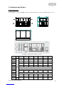
Packing dimensions
The following table, referred to the figure, shows the characteristic dimensions of the series HPH and its accessories.
S = Supply, E = Exhaust, R = Return F = Fresh air
S = Supply, E = Exhaust, R = Return F = Fresh air
HPH 14 20 26 50 92 144 205
A
mm
2185 2185 2515 2845 3175 3505 3835
B 1030 1195 1360 1690 2020 2350 2350
C 1190 1190 1190 1520 1850 2180 2510
L 620 785 950 1280 1610 1940 1940
H 475 475 475 640 805 970 1135
L1 150
L2 100
L3 635 635 635 800 965 965 965
L4 535
W1 620 785 950 1280 1610 1940 1940
H1 455 455 455 620 785 950 1115
Weight kg 550 650 800 1000 1200 1550 1850
160 H 40 H 40
40 L 370
C
B
A
R
SE
F

MIUM0014_REV01_ HP_20151009-MIUM-ENG
6
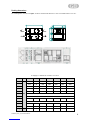
Packing dimensions
The following table, referred to the figure, shows the characteristic dimensions of the series HPR and its accessories.
S = Supply, E = Exhaust, R = Return F = Fresh air
HPR 14 20 26 50 92 144 205
A
mm
2185 2185 2185 2185 2350 2350 2515
B 1030 1195 1360 1690 2020 2350 2350
C 1190 1190 1190 1520 1850 2180 2510
L 620 785 950 1280 1610 1940 1940
H 475 475 475 640 805 970 1135
L1 150
L2 100
L3 635 635 635 800 965 965 965
L4 535
W1 620 785 950 1280 1610 1940 1940
H1 455 455 455 620 785 950 1115
Weight kg 470 560 640 890 1120 1360 1630
R
S
F
E
40 L 370
40H40H160
C
BA

MIUM0014_REV01_ HP_20151009-MIUM-ENG
7
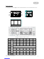
Packing dimensions
The following table, referred to the figure, shows the characteristic dimensions of the series HPS and its accessories.
S = Supply, E = Exhaust, R = Return F = Fresh air
S = Supply, E = Exhaust, R = Return F = Fresh air
HPS 14 20 26 50 92 144 205
A
mm
2185 2185 2515 2845 3175 3505 3835
B 1030 1195 1360 1690 2020 2350 2350
C 1190 1190 1190 1520 1850 2180 2510
L 620 785 950 1280 1610 1940 1940
H 475 475 475 640 805 970 1135
L1 150
L2 100
L3 635 635 635 800 965 965 965
L4 535
W1 620 785 950 1280 1610 1940 1940
H1 455 455 455 620 785 950 1115
Weight kg 470 560 640 890 1120 1360 1630
R
SE
F
160 H 40 H 40
40 L 370
C
B
A

MIUM0014_REV01_ HP_20151009-MIUM-ENG
8
3
–
T
RANSPORTATION
,
H
ANDLING AND
S
TORAGE
Packaging
Each unit is put on bench and protected with cellophane film; the protection must remain intact until the moment of
installation.
The materials that are not mounted for technical motives are supplied in fitted packing fixed externally or internally to the
unit.
Recycle and dispose of packing material in conformity with local regulations, be extremely careful not to damage the unit.
Handling
Comply with the current safety regulations concerning the equipment to use when handling the unit or the required ways
of operating. Use single protection devices as goggles, gloves, helmets when handling the unit to avoid risk of injuries.
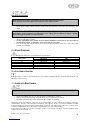
For the lifting and transportation of the unit, use adequate equipment, according to the 89/391/CEE regulations and
further modifications. For lifting, use round bars crossing the baseframe in the prearranged holes and robust ropes as
shown on the below figure.
Each individual unit weight is listed in this manual.
While moving, try to avoid rotation without control.
Check the weight of the unit before proceeding with the moving and handling operations. Make sure that the appliance is
handled with care and without jolting as rough treatment could damage the functional parts
of the machine. To safeguard persons and property, read the information on the packing that covers the unit before
handling.
Also make sure to:
• Handle the machine with care
• Do not stack other objects on top of the unit

MIUM0014_REV01_ HP_20151009-MIUM-ENG
9
Before positioning please consider the overall dimensions and the technical space requirements of the system and the
unit, electric and hydraulic connections and any air pipes/ducts or free passages.
Neglecting these aspects may decrease performance and operational life of the unit and therefore increase the operating
costs and maintenance.
Units are designed to be installed INSIDE or PARTIALLY OUTSIDE (roof cover needed) and in fixed positions.
Before placing the unit be sure that:
• the location is in a safe accessible place
• the framework or the floor or ceiling is adequate to support the weight of the unit, please refer to weight paragraph
• support points are leveled and aligned
• the place can not be subject to flooding
• the maximum level of the snow does not obstruct the airflow to the unit
To ensure the best air circulation to the unit and thus ensure a smooth operation it is recommended to:
• avoid obstructions to air flow near or above the unit
• protect the unit from high winds that can favor or not the airflow
• protect the unit from heat sources or pollutants (chimneys, extractors…)
• protect the unit from air stratification or recirculation (avoid bad ducting of the fans, containment structure, high walls or
corners next to the unit)
These advises if not respected can lead to a lower efficiency of the unit and possible failures.
Checklist
Upon reception of the unit, we suggest that a complete control is carried out, to verify that the unit is intact and complete,
and no damage has been sustained during transport. Any eventual damage revealed must be communicated to the
carrier, demonstrating the reserve clause within the transport documents, specifying the type of damage.
Storage
The units must be stored in a dry place, sheltered from the sun, rain, sand and wind.
Comply with the storage conditions given below:
• Do not stack the units
• Maximum temperature = 60°C
• Minimum temperature = -20°C
The Manufacturer declines any responsibility for any damage as a result of negligence or lack of protection from
atmospheric agents.

MIUM0014_REV01_ HP_20151009-MIUM-ENG
10
4
–
I
NSTALLATION
&
C
ONNECTIONS
Definitions
CUSTOMER – The Customer is the person, activity or the society, that has bought or hired the unit, and intends to utilize
the machinery for its intended use.
USER / OPERATOR – The User or Operator is the actual person that has been authorized by the Customer to utilize the
unit.
QUALIFIED PERSONNEL - Defined as the person who has followed a relevant specific course of study, and so is able
to understand the dangers derived from the use of the machinery, and in turn, due to this, are capable of solving major
dilemmas.
Safety regulations
• Qualified personnel must carry out the installation.
• During the installation operation, use protective clothing, for example: glasses, gloves, etc. as indicated by
686/89/CEE and successive regulations.
• During the installation operate in absolute security, pollution free air and in an area free of obstructions.
• Respect the regulations in force in the country in which the apparatus is being installed. Specifically relative to
its use, and to the disposal of packing and products used for the cleaning and maintenance of the unit. Respect
the recommendations given by the producers of such products.
• Before placing in function the unit, check the perfect connection of the various components and the internal
parts of the system.
• Avoid at all costs human contact with moving parts and contact with the parts themselves.
• Do not commence with servicing or cleaning of the unit, before the unit has been disconnected from the
main supply.
• The maintenance and the substitution of damaged or consumed parts must be carried out only by specialized
personnel, following the indications found within this manual.
• Spare parts must correspond to the requirements specified by Manufacturer.
• In case of dismantling of the unit, respect the anti-pollution regulations in force.
N.B. The installer and the user of the apparatus must take into account, and solve problems, connected with any other
type of risk that may occur to the unit. For example, risks derived from the entrance of foreign bodies, or risks due to the
presence of flammable or toxic gas.
The Manufacturer declines any responsibility for failure to respect the Safety Regulations and the prevention
as described below.
Furthermore, the Manufacturer declines any responsibility for damage caused by the improper use of the
unit and/or modifications carried out without proper authorisation.

MIUM0014_REV01_ HP_20151009-MIUM-ENG
11
Preliminary operations
• Check the perfect condition of the various components of the unit.
• Control that contained within the packing, there are the installation accessories, and documentation.
• Transport the packed section as close as is possible to the intended place of installation.
• Do not place tools or weight on top of the packed unit.
Choosing place of installation
• Position the unit on a solid structure, capable supporting the weight of the machine; on each support point install
vibration damper device in order to reduce vibration transmission.
• Position the unit in a point where the condensation discharge may occur easily; tilt the machine towards the
water discharge connection (3° min)
• Do not position the unit in an area in which flammable gases, acidic or corrosive substances are present. They
may damage various components in an irreparable manner.
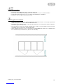
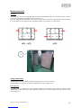
• Allow a minimum amount of free space as indicated in the following figure. This permits ease of installation and
both scheduled and special maintenance (where B is the unit width).

MIUM0014_REV01_ HP_20151009-MIUM-ENG
12
Air duct connections
• The ducts must be correctly sized, in order to match unit external static pressure at duty airflow rate.
• To prevent the water condensation and cut down the sound level it is suggested to install insulated air ducts or
provide a duct insulation.
• Between unit and air ducts always install suitable flexible joints; anyway, the electrical continuity must be
ensured between air ducts (if metal type) and unit by a ground cable.
Water connections
The installation and connecting of the piping is an operation that must be done correctly, otherwise it may compromise
the performance of the system. At worst it may cause irreversible damage to the machine. These operations are to be
effectuated by qualified personnel.
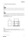
Condensation outlet connection
• Condensation outlet connections are on the opposite side to that of compressor and electric box.
• The system of drainage must provide, for each outlet, an adequate trap able to allow the condensation run off
on underpressure conditions.
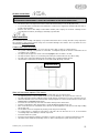
• The trap must be designed as shown on the following figure, where H shall be > 50 mm
• The trap must have a tap for correct cleaning of the lower part, and must allow an easy disassembly.
• The path of the condensation drainage tube must always have a gradient toward external.
• Insure that the condensation run-off tube does not interfere with discharge of the unit.
Liv e llo c ond en s a
Co nde ns a te le v el
Water coil connection (optional CCS section)
• The water heating or cooling coil (CCS) is supplied with GAS “male” threaded headers.
• The tightening must be carried out with extreme care to avoid damage to the copper collectors of the coil.
• The path of the tubes must be studied in a way to avoid obstacles should it be necessary to extract the unit coil.
• Inlet and outlet water must consent the thermal exchange against the current. Follow instructions found on the
WATER INLET and WATER OUTLET plate.
• Provide an air valve at the top of the unit, and a water discharge valve at the bottom.
• Reinforce sufficiently the units external tubes to avoid offloading the weight onto the coil.
• Once connection has been effectuated, fix the external seal flush against the control panel, in this way avoiding
the passing of air.
• The insulation must not rest against the paneling, as this may provoke burning.
• For control purposes, organize the interception of the tube side coil when the fan is off, to avoid internal
overheating and possible damage to internal components.
• Provide an anti-freeze system.
• Provide a cut out switch to isolate the coil from the rest of the circuit in case of extensive maintenance needs.
• Should the unit be installed in particularly cold areas, drain completely before plant shut-off long periods.
IMPORTANT: IT IS IMPORTANT NOT TO PLACE IN OPERATION THE UNIT IF THE FAN OUTLETS ARE
NOT
DUCTED OR NOT PROTECTED BY A SAFETY NET ACCORDING TO THE ACTUAL REGULATION.

MIUM0014_REV01_ HP_20151009-MIUM-ENG
13
Electrical connections
Qualified personnel according to the supplied schemes must carry out the electrical connections at the control panel.
• Insure that the voltage and the frequency shown on the technical plate correspond to the connecting power
supply.
• For the main power supply of the unit and its possible accessories, the use of adapters, multiple plugs and
extension leads shall be avoided.
• It is the responsibility of the installer to insure that the installation of the unit is as close as possible to
the main power supply, or sufficiently close to protect the electrical parts.
• Connect the unit to an efficient power point, by using the glands near the electric box panel; power supply
terminals are screw type.
5
–
W
IRING
D
IAGRAMS
Follow wiring diagram attached to every unit inside the electrical board.
Unit model
Series / Document code
HPH & HPS
HPR
14-20-26 AMF0007823 AMF0007818-AMF0008055-AMF0008055
50 AMF0007473 AMF0007819
92 AMF0007824 AMF0007820
144 AMF0007825 AMF0007821
205 AMF0007826 AMF0007822
6
–
E
LECTRONIC
C
ONTROL
Follow instructions on HP user manual attached to every unit and contained inside the electrical board (document code
MC00005, valid for all sizes).
7
–
S
CHEDULED
M
AINTENANCE
• It is the responsibility of the User to carry out all types of maintenance operations.
• Only personnel previously trained and qualified may carry out maintenance operations.
• Should the unit require disassembly, hand and body protections are required
Maintenance keeps unit efficiency, reduce the speed of deterioration over time and collect information and data to
understand the efficiency of the unit and prevent failures. We suggest to prepare a booklet of installation according
European legislation. Provide a machine book that allows you to track of the actions taken on the unit, so it will be easier
to cadence adequately the various interventions and will facilitate a possible troubleshooting.
Please take note of: date, type of action, description of action, measurements performed, anomalies identified, alarms
registered in the alarm history, etc.
Before starting any operation, insure that the general power supply has been isolated.
All the electrical connections must be protected at the source by the installer.
Follow the connectio
n of the unit and its accessories using adequate cabling for the power used, and
respecting the country regulations. The dimensions of the cabling must be sufficient to support a voltage
drop in start up phase inferior to 3% of the nominal.
BEFORE SERVICING THE UNIT, SWITCH OFF THE MAIN POWER SUPPLY.

MIUM0014_REV01_ HP_20151009-MIUM-ENG
14
Monthly maintenance
Air filters
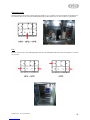
Each filter section can be entered through hinged side panel, provided with handle; once entered, filter can be removed
by side after removing the vertical filter frame by an Allen key (1).
This unit is equipped with soft bag filters; since they are not cleanable, check them monthly and replace them when dirty.
For an automatic pressure drop limit control, installation of filter pressure switches is recommended.
Yearly maintenance
Check that all the electrical equipment, in particular the fixing of the electrical connections.
Check the tightness of all nuts, bolts, flanges and hydraulic connections; tighten if loose.
Heat recovery
It generally requires no maintenance; just for checking cleaning of heat exchange surface and by-pass device for HPH
and HPS units or wheel driver (motor, pulley and belt) for HPR units, unscrew the fixing panels on the opposite side of
that of compressor.
1

MIUM0014_REV01_ HP_20151009-MIUM-ENG
15
Refrigerant circuit
Check the whole circuit in order to find possible gas leakage. In case of leakage, previously empty the circuit and recover
the refrigerant. Remove the lower panel with built-in handles, fixed by panel locks, to enter compressor compartment.
Fans
Each fan section can be entered through hinged side panel, provided with handle. Check that each impeller is clean and
free to rotate.

MIUM0014_REV01_ HP_20151009-MIUM-ENG
16
Water coil (optional CCS section)
By unscrewing and removing the panel on the opposite side to that of water connection, check that the heat exchange
surface is clean and fins are in perfect condition.
8
–
T
ROUBLESHOOTING
Failure searching and problem solving schedule
The following table is for possible failures of air plant system; for errors and alarms displayed by the control panel, see
control user manual.
Founded failure
Probable cause
Possible solution
Fans are not running
• Power supply is switched off
• Wrong or loose electrical
connections
• Motors on thermal protection mode
• Fan signal missing
• Switch on the power supply
• Restore the right connections
• Check motor current
• Check signal connections
Compressor is not running • Thermal protection on
• Too high or too low freon pressure
• Check compressor working
conditions
Air performance decreasing • Air filter dirty
• Air duct blocked
• Clean or replace filter
• Check air system (are dampers
open ?)
Insufficient heating or cooling
performance
• Temperature setpoint not correct
• Refrigerant filling not correct
• Refrigerant leakage
• Required performance not met by
compressor capacity
• Unit on defrost mode
• Compressor cooling capacity
reduced because of too high
condensing pressure
• Adjust the right temperature
setpoint, compatibly with outdoor
and indoor condition and
compressor capacity limit
• Check possible leakage points
• Refill refrigerant
Too high defrost cycle frequency • Too cold outdoor air and/or indoor air
• Too low return airflow
• Preheat air
• Start the unit after room is
preheated
• Check return air filter and
return/exhaust air circuit
Condensate water stays inside the
unit
• Condensate drainage blocked
• Missing or not adequate trap
• Clean or free the drainage
• Install a right trap
9
–
M
ATERIAL
D
ISPOSAL
At the end of unit’s lifetime, its components must be dismantled and disposed of respecting the operational regulations
present in its country of installation.
The materials that the unit is constructed of are:
- Precoated galvanized steel sheet metal
- Galvanized steel sheet metal
- Aluminum
- Copper
- Polyester
- Polyethylene
- Glass wool
- Plastic
During disconnection of the unit, avoid gas leakage or liquid spillage on environment, especially if the water has additives
like glycol. For dismissing and disposal, deliver the units to specialized centers according to your national laws.
-
 1
1
-
 2
2
-
 3
3
-
 4
4
-
 5
5
-
 6
6
-
 7
7
-
 8
8
-
 9
9
-
 10
10
-
 11
11
-
 12
12
-
 13
13
-
 14
14
-
 15
15
-
 16
16


LMF Clima HPS 26 Installation, Operation and Maintenance Manual
- Category
- Split-system air conditioners
- Type
- Installation, Operation and Maintenance Manual
- This manual is also suitable for
Ask a question and I''ll find the answer in the document
Finding information in a document is now easier with AI