WaterWorks LDXT40 Installation guide
- Category
- Sanitary ware
- Type
- Installation guide
This manual is also suitable for

PRODUCT SUPPORT | 800.927.2120 | WATERWORKS.COM PAGE 1 OF 3 | UPDATED ON 9.07.2022
INSTALLATION GUIDELINES
EXPOSED TUB FILLER
IMPORTANT:
¾To ensure this product is installed properly, you must read and follow these
guidelines.
¾The owner/user of this product must keep this information for future reference.
¾This product must be installed by a professional licensed contractor and must
be on-site prior to rough-in. This allows the installer to visualize the installation
and verify the 8” [203mm] on-center inlet supply spread. The inlet supply spread
on this product is NOT adjustable.
¾Check TUB measurements to ensure the SPOUT project far enough into the TUB.
¾Run 3/4” supply lines for MAXIMUM flow and install ACCESSIBLE hot and cold
service stop valves to facilitate servicing.
¾Be sure your installation conforms to federal, state, and local codes.
●Anti-scaled protection is the responsibility of the installer and according to
applicable codes.
●A water temperature limiting device is the responsibility of the installer and
must be in accordance with ASSE 1070.
●In the State of Massachusetts, all installations must comply with the rules
and regulations set forth within 248 CMR.
¾Inspect this product to ensure you have all the parts required for proper
installation.
¾Product is sold partially assembled but shown fully disassembled for illustrative
and service purposes only.
¾Use only a strap wrench or protected/smooth-jaw wrench on any finished surface.
¾The use of certain plumber’s putty may stain stone or tile surfaces.
¾If further assistance is required, please contact Product Support at 1-800-927-
2120 Monday through Friday, 8am – 6pm EST.
¾Refer to the separate Service Parts Documents for available replacement parts.
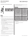
TECHNICAL DETAILS:
DETAIL SPECIFICATION
DIAMETER OF HANDSHOWER HEAD 2-1/8” [54mm]
DECK THICKNESS MAXIMUM 1-1/2” [38mm]
FITTINGS HOLE DIAMETER 1 1/4” [32 mm]
HANDLE TURN ANGLE QUARTER TURN
HOSE LENGTH 59” [1.5m]
INLET CONNECTION 3/4” MALE NPT †
INLET SUPPLY SPREAD 8” [203mm]
[NOT ADJUSTABLE]
INTEGRATED DIVERTER YES
SPOUT REACH 8 9/16" [217mm]
WATER PRESSURE MAXIMUM 85psi [6.0 bar]
WATER PRESSURE MINIMUM 20psi [1.5 bar]
WATER PRESSURE RECOMMENDED 45psi [3.0 bar]
† Style No. LD40XT and LD50XT are provided with 2 BSPP ADAPTERS. ADAPTERS
are packaged separately and assembly is required. Replacement ADAPTERS can
be ordered separately:
●Universal 3/4” NPT Female x 3/4” Male BSPP Adapter
Style No. UNUK05
STYLES
LDXT40 [SHOWN] LD40XT LDXT50
LD50XT
LUDLOW EXPOSED TUB FILLER WITH HANDSHOWER AND HANDLES

PRODUCT SUPPORT | 800.927.2120 | WATERWORKS.COM PAGE 2 OF 3 | UPDATED ON 9.07.2022
INSTALLATION GUIDELINES
EXPOSED TUB FILLER
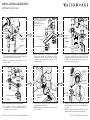
ESUTCHEON
[WITH
WASHER]
SHANK
SPOUT
SET SCREW
[2.5mm HEX]
SPOUT FACING
TOWARDS
TUB
O-RING]
MOUNTING
SURFACE
NUT
RUBBER WASHER
SHANK
ESCUTCHEON†
A WASHER for the ESCUTCHEONS
is provided. If desired, a bead of
caulk or clear silicone may be
applied where the
ESCUTCHEON contact the
mounting surface.
†
SHANK
3/4" NPT X
SWEAT
ADAPTER
3/4"
SUPPLY
LINE
[PRE-SWEAT
JOINT]
[NOT
SUPPLIED]
SHANK
3/4" BSPP ADAPTER
[INTERNATIONAL
USE ONLY]
HOSE
[CONICAL
END]
HANDSHOWER
FLOW
REGULATING
CHECK
VALVE
RETAINING
CLIP
[15mm BORE]
HOOK
SUPPLY ELBOW
[1/2" MALE
THREAD]
HOSE
[HEX END]
1. Align the SPOUT properly and securely tighten the
SET SCREW at the base of the SPOUT then slide
the ESCUTCHEONS onto the SHANKS.
NOTE: Do NOT remove the O-RING on the
ESCUTCHEONS.
2. Insert the SHANKS into the holes on the mounting
surface then attach the RUBBER and METAL
WASHERS and NUTS onto the SHANKS. Securely
tighten the NUTS against the underside of the
mounting surface.
3. Pre-sweat 3/4” female NPT x sweat adapters to
3/4” supply lines and let cool. Apply a thin coat
of pipe thread sealant to the male threads on the
SHANKS then thread and securely tighten the
ADAPTERS onto the SHANKS.
FOR INTERNATIONAL INSTALLATIONS ONLY
4. 3/4” female NPT x 3/4” male BSPP ADAPTERS
are provided. Thread and securely tighten the
ADAPTERS onto the SHANKS.
5. Thread the HEX END of the HOSE to the SUPPLY
ELBOW on the VALVE BODY.
NOTE: A CHECK VALVE is located inside the outlet
of the ELBOW.
6. Thread the conical end of the HOSE to the
HANDSHOWER then rest the HANDSHOWER on
the HOOK.
NOTE: A FLOW REGULATING CHECK VALVE is
located inside the inlet of the HANDSHOWER.

PRODUCT SUPPORT | 800.927.2120 | WATERWORKS.COM PAGE 3 OF 3 | UPDATED ON 9.07.2022
INSTALLATION GUIDELINES
EXPOSED TUB FILLER
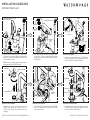
SERVICING THE VALVE BODY
1. If the entire BODY needs to be replaced, unthread
BOTTOM CAPS and slide them down the legs to
access the UNION CONNECTIONS.
SERVICING THE DIVERTER
1. Pull the DIVERTER KNOB to expose the DIVERTER
NUT then unthread and remove the DIVERTER
using a 19mm wrench.
7. Remove the AERATOR using the TOOL provided
then turn on the water supply and operate the
HANDLES to flush out the supply lines and check
all connections for leaks.
NOTE: Ensure the supply lines have been flushed
before operating the DIVERTER KNOB.
8. With water running, operate the DIVERTER KNOB
to ensure it and the HANDSHOWER function
properly then turn off the water, and then Re-install
the AERATOR.
SERVICING THE SPOUT
1. Loosen, but do NOT remove, the SET SCREW at
the base of the SPOUT then remove the SPOUT to
expose the POST and external O-RINGS
SERVICING THE CARTRIDGE
1. Unthread the GLAND COVER to remove the
HANDLE then remove the CARTRIDGE using a
21/32” [17mm] shower valve socket wrench (not
supplied).
POST
SPOUT
O-RINGS
POST
SET SCREW
[2.5mm HEX]
CARTRDIGE
GLAND COVER
HANDLE
DIVERTER
KNOB
DIVERTER NUT
BOTTOM CAP
UNION NUT
DIVERTER
DIVERTER KNOB
CARTRDIGE
HANDLE
TURN ON WATER SUPPLY AND
CHECK FOR LEAKS!
*
AERATOR
AERATOR
TOOL
HANDSHOWER
DIVERTER
KNOB
[PULL]
AERATOR
AERATOR
TOOL
-
 1
1
-
 2
2
-
 3
3


WaterWorks LDXT40 Installation guide
- Category
- Sanitary ware
- Type
- Installation guide
- This manual is also suitable for
Ask a question and I''ll find the answer in the document
Finding information in a document is now easier with AI
Related papers
-
WaterWorks CXT201 Installation guide
-
-
-
-
-
-
-
-
-
Other documents
-
American Standard 7420.901.224 Installation guide
-
-
-
-
aquabrass 86013 Installation guide
-
-
Speakman SM-5070 Installation guide
-
-
-