Page is loading ...

INSTALLATION, OPERATION & MAINTENANCE MANUAL
ENERGY RECOVERY VENTILATOR
HE1XRTC
HE2XRTC
HE3XRTC
HE4XRTC
RENEWAIRE.COM
MODEL: HE1XRTC
MODEL: HE2XRTC
MODEL: HE3XRTC

ERV RTC
RENEWAIRE.COM INSTALLATION, OPERATION AND MAINTENANCE MANUAL 1.800.627.44992
RTC info ............................. 2-12
Installation ....................... 12-23
Start-up & Operation .........24-29
Maintenance .....................30-35
TABLE OF CONTENTS
RTC INFO
RTC CONFIGURATION CHART
MODEL NUMBER
1 2 3 4 5 6 7 8 9 10 11 12 13 14 15 16 17 18 19 20 21 22 23 24 25
J - - -
DIGIT NUMBER
Wall Type
Digit 11:
"S" = Single
"D" = Double
Phase
Digit 12:
"1" = Single Phase
"3" = Three Phase
Digit 13:
"1" = 115V
"4" = 460V
"5" = 208-230V
"8" = 575V
"9" = 277V
FA Horsepower (see Restriction 5 and 6)
Digit 14:
"H" = 0.75 HP Standard Direct-Drive (HE-1X only)
"E" = EC Direct Drive Motors ( HE-1X only)
"V" = 2HP (HE-2X only)
"W" = 3HP (HE-3X only)
"X" = 5HP (HE-4X only)
*NOTES:
Digit 6 "J" = G5 Core Type Digits 10, 16, 17 and 18 are not used in these models.
Restrictions:
1: Voltage Codes "1" and "9" only available with Phase Code "1" (Single-Phase).
2: Voltage Codes "4" & "8" only available with Phase Code "3" (Three-Phase).
3: Voltage Code "9" only available with FA/EA Horsepower Codes "H" and "E".
4: Voltage Code "1" only available with FA/EA Horsepower Codes "V", "H" and "E".
5: FA/EA Horsepower Codes "E" only available in Phase Code "1".
6: FA/EA Horsepower Codes "X" only available in Phase Code "3".
7: Unit Control Code "G" only available with FA/EA Horsepower Codes "E".
8: Some units with Customization Code "X" are not safety listed.
9: Unit Control Codes "V", "E" & "F" not available with Voltage Code "1".
10: Unit Control Code "V", "E" & "F" not available with FA/EA Horsepower Code "E".
Digit 19:
"A" = Standard Unit Control Wiring
"V" = Onboard VFD Both Airstreams
"F" = Onboard VFD FA Airstream
"E" = Onboard VFD EA Airstream
"G" = Terminal Strip for EC Motors
Disconnect
Digit 20:
"N" = Non-Fused (Standard)
"F" = Fused
Unit Control Enhancements
Digit 21:
"T" = Transformer with Isolation Relay (Standard)
"1" = Enhanced Controls
"2" = Premium Controls
"3" = Enhanced Controls with BACNET License
"4" = Premium Controls with BACNET License
Filter Options
Digit 22:
"-" = None
"F" = Filter Monitor Both Airstreams
Other Options
Digit 23:
"-" = None (Reserved)
Paint and Customization
Digit 24:
"-" = None
"W" = White Paint
"C" = Custom Paint
"X" = Custom Unit
Digit 25:
"L" = Listed
"N" = Non-Listed
-RT
"HE-1X", "HE-2X", "HE-3X", "HE-4X"
Model
Digits 1-5:
Unit Control (see Restrictions 7, 9 & 10)
Safety Listing (see Restriction 8)
Voltage (see Restrictions 1, 2, 3 & 4)
C
EA Horsepower (see Restriction 5 and 6)
Digit 15:
"H" = 0.75 HP Standard Direct-Drive (HE-1X only)
"E" = EC Direct Drive Motors ( HE-1X only)
"V" = 2HP (HE-2X only)
"W" = 3HP (HE-3X only)
"X" = 5HP (HE-4X only)
-
RTC MODEL
PRODUCT CODE CHART
NOTE: RenewAire reserves the right to make changes in the design or specifications of products at any time without notice. Unless otherwise
specified, dimensions are rounded to the nearest eighth of an inch.

ERVRTC
3 1.800.627.4499 INSTALLATION, OPERATION AND MAINTENANCE MANUAL RENEWAIRE.COM
Specifications may be subject to change without notice.
1. Before servicing or cleaning the unit, switch
power off at disconnect switch or service panel
and lock-out/tag-out to prevent power from
being switched on accidentally. More than
one disconnect switch may be required to de-
energize the equipment for servicing.
2. This installation manual shows the suggested
installation method. Additional measures may
be required by local codes and standards.
3. Installation work and electrical wiring must be
done by qualified professional(s) in accordance
with all applicable codes, standards and
licensing requirements.
4. Any structural alterations necessary
for installation must comply with all
applicable building, health, and safety code
requirements.
5. This unit must be grounded.
6. Danger of severe injury to bystanders and
damage to unit or property if high winds move
this unit. Secure this unit to the building!
7. Sufficient air is needed for proper combustion
and exhausting of gases through the flue
(chimney) of fuel burning equipment that
might be installed in the area affected by this
equipment. If this unit is exhausting air from a
space in which chimney-vented fuel burning
equipment is located, take steps to assure that
combustion air supply is not affected. Follow the
heating equipment manufacturer’s requirements
and the combustion air supply requirements of
applicable codes and standards.
8. Use the unit only in the manner intended by the
manufacturer. If you have questions, contact
the manufacturer.
9. This unit is intended for general ventilating only. Do
not use to exhaust hazardous or explosive materials
and vapors. Do not connect this unit to range hoods,
fume hoods or collection systems for toxics.
10. When cutting or drilling into wall or ceiling,
do not damage electrical wiring and other
hidden utilities.
RISK OF FIRE, ELECTRIC SHOCK, OR INJURY. OBSERVE ALL CODES AND THE FOLLOWING:
WARNING
Danger of Electrical Shock when servicing an installed unit.
ALWAYS DISCONNECT POWER SOURCE BEFORE SERVICING! More than one disconnect switch may be
required.
Proper Wiring Size Selection and Wiring Installation are the Responsibility of the Electrical Contractor.
WARNING
DANGER OF INJURY
OR DAMAGE.
The relay must be set for correct
FLA rating depending on the
motor horsepower. See Unit
Rating Label on motor for HP and
FLA specifications.
WARNING
DANGER OF INJURY OR DAMAGE.
The motors in this unit must not be run at an amperage that exceeds the motor’s rated full load amps and
overload relays on the motor starters must be set at or below motor full load amps. For safest operation, the
overload relays should also be used in hand reset mode with trip test capability.
It is the installer’s responsibility to measure the operating amperage of each motor. If the full load amp
rating is exceeded, the amp draw must be reduced by substituting a smaller motor pulley or by adjusting
the variable sheave. Continue these adjustments until the actual amperage is no more than the motor’s
faceplate full load amps.
Failure to make this adjustment may result in unsafe motor winding temperatures or tripping of the supplied
motor starter’s overload relay motor protection devices set at full load amps.
WARNING

RENEWAIRE.COM INSTALLATION, OPERATION AND MAINTENANCE MANUAL 1.800.627.44994
RENEWAIRE.COM 1.800.627.4499
30
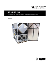
SPECIFICATIONS & DIMENSIONS
Specifications may be subject to change without notice.
ROOFTOP UNIT
Direct Connect
SPECIFICATIONS
Ventilation Type:
Static plate, heat and humidity transfer
Typical Airflow Range: 500-900 CFM
AHRI 1060 Certified Core: One L125-G5
Standard Features:
Non-fused disconnect
24 VAC transformer/relay package
Filters:
Total qty. 2, MERV 8: 20" x 20" x 2"
Unit Dimensions & Weight:
73 1/4" L x 40 1/4" W x 50" H
269-356 lbs., varies by option(s)
Max. Shipping Dimensions & Weight (on pallet):
96" L x 47" W x 50" H
450 lbs.
Motor(s):
Qty. 2, 0.75 HP ea., Direct drive blower/standard
motor packages
Options:
Qty. 2, EC Motor (see HE1XRTC EC Motor submittal) -
0.5 HP 120V/1Ph/60HZ,
0.5 HP 208-230V/1Ph/60HZ
Integrated programmable controls
Fused disconnect
Double wall construction
Qty. 2, Factory mounted filter alarms
Independent blower control
Exterior paint - white, custom colors
Rooftop RTC transition paint - white, custom colors
Accessories:
Filters - MERV 13, 2" (shipped loose)
RTC transition kit - for vertical RTU, for horizontal RTU
Digital time clock - wall mount (TC7D-W),
in exterior enclosure (TC7D-E)
Motion occupancy control - ceiling mount (MC-C),
wall mount (MC-W)
Carbon dioxide control - wall mount (CO2-W),
duct mount (CO2-D)
HP Volts HZ Phase
FLA
per
motor
Min.
Cir.
Amps
Max.
Overcurrent
Protection
Device
0.75 120 60 Single 9.0 20.3 25
0.75 208-230 60 Single 4.5 10.1 15
0.75 277 60 Single 3.9 8.8 15
0.75 208-230 60 Three 1.7-2.3 5.2 15
0.75 460 60 Three 1.15 2.6 15
ELECTRICAL DATA
ThermalPerformanceRatingsG52015.2.xlsx HE1X(IOM)
30%
50%
70%
90%
200 400 600 800 1000
Effectiveness (%)
Airflow (CFM)
CORE PERFORMANCE
At AHRI 1060 standard conditions. See all AHRI certified ratings at www.ahrinet.org.
Damper
Position
Total Watts
Tie-In Directly to Rooftop A/C Unit Unit Ducted Independently
Static Pressure in Adjacent Air Handler
(Inches Water Column)
External Static Pressure
(Inches Water Column)
1 Phase 3 Phase -0.75 -0.5 -0.25 0.0 +0.25 +0.5 +0.75
EA FA EA FA EA FA EA FA EA FA EA FA EA FA
100% Open 1,295 1,135 735 1035 865 990 920 945 975 890 920 845 865 790 735 605
65% Open 1,285 1,088 715 995 825 950 880 905 935 855 880 805 825 760 715 605
55% Open 1,275 1,074 715 980 815 935 870 890 925 845 870 795 815 755 715 615
45% Open 1,265 1,030 680 940 790 895 840 850 895 810 840 760 790 720 680 570
35% Open 1,265 951 630 865 745 825 795 785 850 745 795 700 745 665 630 515
25% Open 1,265 866 570 795 700 755 750 715 800 680 750 640 700 605 570 440
15% Open 1,260 774 510 725 655 685 705 645 750 615 705 580 655 545 510 365
AIRFLOW PERFORMANCE
Note: Watts is for the entire unit (2 motors).
Refer to IOM for more details.
Note: Airflow performance includes effect
of clean, standard filter supplied with unit.
Installation Details - Applicable to all RTC units
www.renewaire.com (800) 627- 4499 [email protected]
Note: Electric Duct Heater and Indirect Gas-Fired Duct Furnace are not available on RTC units.
1XRTCHE Energy Recovery Ventilator
Standard
Download specification at:
renewaire.com/specifications
Specifications may be subject to change without notice.

5 1.800.627.4499 INSTALLATION, OPERATION AND MAINTENANCE MANUAL RENEWAIRE.COM
FOR THE MOST COMPLETE AND CURRENT INFORMATION VISIT RENEWAIRE.COM
HE-SERIES
31
33 3/4" Minimum
Service Area
51" Minimum
Service Area
45 3/4"
Lifting Lugs
73 1/4" Overall
Control Wiring
Inlet
7/8"
Power Wiring
Inlet
7/8"
FRONT VIEW
Disconnect
Switch
Pressure
Ports (4) Typ.
EA Outlet
at Back
EA
RA
OA
FA
41 1/4" Case
49 7/8" Overall
2" Typ.
20 1/8"
Lifting Lugs
16"
2"
8 3/8"
14 1/2" to 17 1/2"
Height
Adjustment
11"
Typ.
3 1/2"
40 1/4" Overall
22 1/2" Case
51" Case
TOP VIEW
LEFT VIEW
RIGHT VIEW
Door
Swing
Door
Swing
33 3/4" Minimum
Service Area
51" Minimum
Service Area
Model: HE1XRTC
Drawing Type: Unit Dimension
Version: MAY18
ABBREVIATIONS
EA: Exhaust Air to outside
OA: Outside Air intake
RA: Room Air to be exhausted
FA: Fresh Air to inside
INSTALLATION ORIENTATION
Unit must be installed in orientation
shown.
NOTE
1. UNLESS OTHERWISE SPECIFIED,
DIMENSIONS ARE ROUNDED TO THE
NEAREST EIGHTH OF AN INCH.
2. SPECIFICATIONS MAY BE SUBJECT
TO CHANGE WITHOUT NOTICE.
HE1XRTC
Energy Recovery Ventilator
Standard or EC Motor Option
AIRFLOW CONFIGURATION
Available as shown in dimension drawing.
UNIT MOUNTING & APPLICATION
Must be mounted as shown. Airstreams can not
be switched.

RENEWAIRE.COM INSTALLATION, OPERATION AND MAINTENANCE MANUAL 1.800.627.44996
RENEWAIRE.COM 1.800.627.4499
60
SPECIFICATIONS & DIMENSIONS
Specifications may be subject to change without notice.
ROOFTOP UNIT
Direct Connect
SPECIFICATIONS
Ventilation Type:
Static plate, heat and humidity transfer
Typical Airflow Range: 500-1,700 CFM
AHRI 1060 Certified Core: Two L125-G5
Standard Features:
TEFC Premium efficiency motors
Motor starters
Non-fused disconnect
24 VAC transformer/relay package
Filters:
Total qty. 4, MERV 8: (2) 20" x 20" x 2" and
(2) 14" x 20" x 2"
Unit Dimensions & Weight:
77 1/4" L x 61" W x 50" H
566-711 lbs., varies by option(s)
Max. Shipping Dimensions & Weight (on pallet):
80" L x 90" W x 50" H
850 lbs.
Motor(s):
Qty. 2, 2.0 HP ea., Belt drive blower/standard motor
packages with adjustable sheaves (see table below)
Options:
Integrated programmable controls
Fused disconnect
Double wall construction
Factory supplied and mounted variable frequency
drives (VFDs) - one or both airstreams
Shaft grounding ring on motors with VFDs
Qty. 2, Factory mounted filter alarms
Exterior paint - white, custom colors
Rooftop RTC transition paint - white, custom colors
Accessories:
Filters - MERV 13, 2" (shipped loose)
RTC transition kit - for vertical RTU, for horizontal RTU
Digital time clock - wall mount (TC7D-W),
in exterior enclosure (TC7D-E)
Motion occupancy control - ceiling mount (MC-C),
wall mount (MC-W)
Carbon dioxide control - wall mount (CO2-W),
duct mount (CO2-D)
ELECTRICAL DATA
Standard Electrical Specifications Optional Factory Installed
VFD Electrical Specifications
HP Volts HZ Phase FLA
per motor
Min. Cir.
Amps
Max.
Overcurrent
Protection
Device
FLA
per motor
Min. Cir.
Amps
Max.
Overcurrent
Protection
Device
2.0
208-230
208-230
460
575
60
60
60
60
Single
Three
Three
Three
10.8-10.0
6.6-5.8
2.9
2.4
24.3
14.9
6.5
5.4
35
20
15
15
6.6-5.8
6.6-5.8
2.9
2.4
28.3
16.3
7.2
5.9
30
20
15
15
ThermalPerformanceRatingsG52015.2.xlsx 2Cores(IOM)
30%
50%
70%
90%
500 1000 1500 2000
Effectiveness
(%)
Airflow(CFM)
CORE PERFORMANCE
At AHRI 1060 standard conditions.
See all AHRI certified ratings at www.ahrinet.org.
AIRFLOW PERFORMANCE
Blower RPM
Nominal
Sheave Adj.
Turns Open
Tie-In Directly to Rooftop A/C Unit* Unit Ducted Independently*
Static Pressure in Adjacent Air Handler
(Inches Water Column) External Static Pressure (Inches Water Column)
-0.75 -0.5 -0.25 0.0 +0.25 +0.5 +0.75
CFM BHP CFM BHP CFM BHP CFM BHP CFM BHP CFM BHP CFM BHP
Exhaust Air
1450 0 1664 1.6 1785 1.9 1785 1.9 1664 1.6
1370 1 1400 1.4 1570 1.6 1740 1.8 1900 1.9 1740 1.8 1570 1.6 1400 1.4
1290 2 1125 1.3 1350 1.4 1575 1.5 1727 1.6 1575 1.5 1350 1.4 1125 1.3
1210 3 945 1.0 1165 1.1 1385 1.3 1560 1.4 1385 1.3 1165 1.1 945 1.0
1130 4 721 0.7 978 0.9 1235 1.1 1365 1.1 1235 1.1 978 0.9 721 0.7
1050 5 560 0.7 810 0.8 1060 0.9 1200 1.0 1060 0.9 810 0.8 560 0.7
945 6 635 0.6 765 0.6 895 0.6 1025 0.7 895 0.6 765 0.6 635 0.6
Fresh Air
1705 0 1600 2.0 1480 1.9 1360 1.7
1610 1 1635 2.0 1555 1.9 1490 1.8 1375 1.7 1260 1.5
1515 2 1742 2.0 1631 1.9 1520 1.7 1430 1.6 1355 1.6 1230 1.4 1105 1.3
1420 3 1620 1.7 1515 1.6 1410 1.5 1300 1.4 1230 1.4 1115 1.2 1000 1.1
1325 4 1465 1.5 1370 1.4 1275 1.3 1190 1.3 1120 1.2 995 1.1 870 0.9
1230 5 1325 1.3 1245 1.2 1165 1.1 1080 1.0 985 0.9 850 0.8 715 0.6
1090 6 1170 1.0 1085 0.9 1000 0.8 905 0.8 824 0.7 743 0.6 662 0.6
Note: Brake Horse Power (BHP) is for one blower motor package only. Operation in this zone will likely exceed FLA limits.
Note: Airflow performance includes effect of clean, standard filter supplied with unit.
* See page 30 for installation details.
Note: Electric Duct Heater and Indirect Gas-Fired Duct Furnace are not available on RTC units.
2XRTCHE Energy Recovery Ventilator
Standard
HE
Download specification at:
renewaire.com/specifications
Specifications may be subject to change without notice.

7 1.800.627.4499 INSTALLATION, OPERATION AND MAINTENANCE MANUAL RENEWAIRE.COM
FOR THE MOST COMPLETE AND CURRENT INFORMATION VISIT RENEWAIRE.COM
HE-SERIES
61
77 1/8" Overall
54 7/8"
Lifting Lugs
C
L
2 5/8" Control In
C
L
5 3/4" Power In
FA
RA
EA
Disconnect
Switch
Pressure
Ports (4) Typ.
(2)
7/8" Holes
for Wiring in
Bottom of E-Box
E-Box
57 3/4" Case
1 7/8"
33 7/8"
Minimum
Service Area
67 5/8" Minimum
Service Area
Door
Swing
Door
Swing
C
L
5 1/2"
Wiring
3 5/8" Wiring
39 1/2"
Lifting Lugs
41"
Case
49 7/8" Overall
61" Overall
OA
8 7/8"
11 1/8" Typ.
29"
Typ.
4" Typ.
41 3/4" Case
14 7/8" - 17 5/8"
Height Adjustment
17 7/8"
23 3/8"
1 1/8"
Typ.
2 1/8"
Typ.
RIGHT VIEW
FRONT VIEW
LEFT VIEW
TOP VIEW
Model: HE2XRTC
Drawing Type: Unit Dimension
Version: MAY18
ABBREVIATION
EA: Exhaust Air to outside
OA: Outside Air intake
RA: Room Air to be exhausted
FA: Fresh Air to inside
INSTALLATION ORIENTATION
Unit must be installed in orientation
shown.
NOTE:
1. UNLESS OTHERWISE SPECIFIED,
DIMENSIONS ARE ROUNDED TO THE
NEAREST EIGHTH OF AN INCH.
2. SPECIFICATIONS MAY BE SUBJECT
TO CHANGE WITHOUT NOTICE.
HE2XRTC Energy Recovery Ventilator
Standard
AIRFLOW CONFIGURATION
Available as shown in dimension drawing.
UNIT MOUNTING & APPLICATION
Must be mounted as shown. Airstreams can not
be switched.

RENEWAIRE.COM INSTALLATION, OPERATION AND MAINTENANCE MANUAL 1.800.627.44998
RENEWAIRE.COM 1.800.627.4499
72
SPECIFICATIONS & DIMENSIONS
Specifications may be subject to change without notice.
SPECIFICATIONS & DIMENSIONS
ROOFTOP UNIT
Direct Connect
Ventilation Type:
Static plate, heat and humidity transfer
Typical Airflow Range: 1,100-2,400 CFM
AHRI 1060 Certified Core: Three L125-G5
Standard Features:
TEFC Premium efficiency motors
Motor starters
Non-fused disconnect
24 VAC transformer/relay package
Filters:
Total qty. 5, MERV 8: (3) 20" x 20" x 2" and
(2) 16" x 25" x 2"
Unit Dimensions & Weight:
81 1/4" L x 63 1/2" W x 48 1/4" H
713-1,084 lbs., varies by option(s)
Max. Shipping Dimensions & Weight (on pallet):
80" L x 90" W x 80" H
1,225 lbs.
CORE PERFORMANCE
ThermalPerformanceRatingsG52015.2.xlsx 3Cores(IOM)
30%
50%
70%
90%
500 1000 1500 2000 2500 3000 3500
Effectiveness
(%)
Airflow(CFM)
ELECTRICAL DATA
Standard Electrical Specifications Optional Factory Installed
VFD Electrical Specifications
HP Volts HZ Phase FLA
per motor
Min. Cir.
Amps
Max.
Overcurrent
Protection
Device
FLA
per motor
Min. Cir.
Amps
Max.
Overcurrent
Protection
Device
3.0
208-230
208-230
460
575
60
60
60
60
Single
Three
Three
Three
14.7-14
9.4-8.5
4.2
3.3
33.1
21.1
9.5
7.4
40
25
15
15
9.4-8.5
9.4-8.5
4.24
3.3
40.2
23.2
10.5
8.2
45
25
15
15
SPECIFICATIONS
At AHRI 1060 standard conditions.
Motor(s):
Qty. 2, 3.0 HP ea., Belt drive blower/standard motor
packages with adjustable sheaves
Options:
Integrated programmable controls
Fused disconnect
Double wall construction
Factory supplied and mounted variable frequency
drives (VFDs) - one or both airstreams
Shaft grounding ring on motors with VFDs
Qty. 2, Factory mounted filter alarms
Exterior paint - white, custom colors
Rooftop RTC transition paint - white, custom colors
Accessories:
Filters - MERV 13, 2" (shipped loose)
RTC transition kit - for vertical RTU, for horizontal RTU
Digital time clock - wall mount (TC7D-W),
in exterior enclosure (TC7D-E)
Motion occupancy control - ceiling mount (MC-C),
wall mount (MC-W)
Carbon dioxide control - wall mount (CO2-W),
duct mount (CO2-D)
AIRFLOW PERFORMANCE
Blower RPM
Nominal
Sheave Adj.
Turns Open
Tie-In Directly to Rooftop A/C Unit* Unit Ducted Indendently*
Static Pressure in Adjacent Air Handler
(Inches Water Column) External Static Pressure (Inches Water Column)
-0.75 -0.5 -0.25 0.0 +0.25 +0.5 +0.75
CFM BHP CFM BHP CFM BHP CFM BHP CFM BHP CFM BHP CFM BHP
Exhaust Air
1510 0 2010 2.7 2010 2.7
1465 1 1920 2.3 2130 2.9 2130 2.9 1920 2.3
1420 2 1830 1.9 2035 2.5 2240 3.0 2240 3.0 2035 2.5 1830 1.9
1375 3 1750 1.1 1945 1.9 2140 2.6 2400 2.7 2140 2.6 1945 1.9 1750 1.1
1330 4 1690 1.0 1860 1.5 2030 1.9 2330 2.6 2030 1.9 1860 1.5 1690 1.0
1285 5 1510 0.9 1725 1.0 1940 1.1 2250 2.1 1940 1.1 1725 1.0 1510 0.9
1240 6 1320 0.8 1590 0.5 1860 0.3 2165 1.5 1860 0.3 1590 0.5 1320 0.8
Fresh Air
1825 0 2250 2.9 2100 2.5 1865 2.3 1630 2.1
1770 1 2525 3.0 2338 2.7 2195 2.6 2025 2.3 1785 2.1 1545 1.8
1715 2 2605 2.7 2430 2.6 2255 2.4 2120 2.3 1960 2.0 1700 1.2 1440 1.4
1660 3 2515 2.4 2345 2.2 2175 1.9 2050 1.8 1900 1.6 1620 0.6 1340 1.0
1605 4 2430 2.2 2270 1.8 2110 1.3 1980 1.3 1830 1.3 1560 0.4 1290 0.5
1550 5 2355 1.2 2185 1.1 2015 1.0 1900 0.6 1765 0.4 1540 0.3 1200 0.4
1495 6 2230 0.8 2090 0.7 1950 0.5 1840 0.4 1730 0.3 1500 0.2 1100 0.2
Note: Brake Horse Power (BHP) is for one blower motor package only. Operation in this zone will likely exceed FLA limits.
Note: Airflow performance includes effect of clean, standard filter supplied with unit.
* See page 30 for installation details.
Note: Electric Duct Heater and Indirect Gas-Fired Duct Furnace are not available on RTC units.
3XRTCHE Energy Recovery Ventilator
Standard
HE
Download specification at:
renewaire.com/specifications
See all AHRI certified ratings at www.ahrinet.org.
Specifications may be subject to change without notice.

9 1.800.627.4499 INSTALLATION, OPERATION AND MAINTENANCE MANUAL RENEWAIRE.COM
FOR THE MOST COMPLETE AND CURRENT INFORMATION VISIT RENEWAIRE.COM
HE-SERIES
73
57 1/8" Case
81 1/4" Overall
54 1/2"
Lifting Lugs
C
L
1 1/4" Control In
C
L
5 5/8" Power In
EA
RA
OA
FA
Pressure Ports
(4) Typ.
(2)
7/8" Holes for
Wiring in Bottom
of E-Box
FRONT VIEW
Disconnect
Switch
E-Box
59 3/8"
Lifting Lugs
C
L
5 3/4" Wiring
5" Wiring
OA
EA
LEFT VIEW
6 5/8"
25 5/8"
11 1/4" Typ.
4 3/8" Typ.
29" Typ.
60 1/4" Case
63 1/2" Overall
45 1/4" Case
48 1/8" Overall
RIGHT VIEW
33 7/8" Minimum
Service Area
67 5/8" Minimum
Service Area
TOP VIEW
Door
Swing
Door
Swing
1 1/8"
Typ.
2 1/8"
Typ.
Model: HE3XRTC
Drawing Type: Unit Dimension
Version: MAY18
ABBREVIATIONS
EA: Exhaust Air to outside
OA: Outside Air intake
RA: Room Air to be exhausted
FA: Fresh Air to inside
INSTALLATION ORIENTATION
Unit must be installed in orientation
shown.
NOTE:
1. UNLESS OTHERWISE SPECIFIED,
DIMENSIONS ARE ROUNDED TO THE
NEAREST EIGHTH OF AN INCH.
2. SPECIFICATIONS MAY BE SUBJECT
TO CHANGE WITHOUT NOTICE.
HE3XRTC Energy Recovery Ventilator
Standard
AIRFLOW CONFIGURATION
Available as shown in dimension drawing.
UNIT MOUNTING & APPLICATION
Must be mounted as shown. Airstreams can not
be switched.

RENEWAIRE.COM INSTALLATION, OPERATION AND MAINTENANCE MANUAL 1.800.627.449910
RENEWAIRE.COM 1.800.627.4499
84
SPECIFICATIONS & DIMENSIONS
Specifications may be subject to change without notice.
ROOFTOP UNIT
Direct Connect
Ventilation Type:
Static plate, heat and humidity transfer
Typical Airflow Range: 2,500-3,900 CFM
AHRI 1060 Certified Core: Four L125-G5
Standard Features:
TEFC Premium efficiency motors
Motor starters
Non-fused disconnect
24 VAC transformer/relay package
Filters:
Total qty. 8, MERV 8: (4) 20" x 20" x 2" and
(4) 16" x 20" x 2"
Unit Dimensions & Weight:
81 1/4" L x 83 1/4" W x 48 1/4" H
887-1,169 lbs., varies by option(s)
Max. Shipping Dimensions & Weight (on pallet):
80" L x 90" W x 80" H
1,300 lbs.
ELECTRICAL DATA
Standard Electrical Specifications Optional Factory Installed
VFD Electrical Specifications
HP Volts HZ Phase FLA
per motor
Min. Cir.
Amps
Max.
Overcurrent
Protection
Device
FLA
per motor
Min. Cir.
Amps
Max.
Overcurrent
Protection
Device
5.0
208-230
460
575
60
60
60
Three
Three
Three
14.5-13.4
6.7
5.3
32.6
15.1
11.9
45
20
15
14.5-13.4
6.7
5.3
35.9
16.6
13.1
45
20
15
SPECIFICATIONS
Motor(s):
Qty. 2, 5.0 HP ea., Belt drive blower/standard motor
packages with adjustable sheaves
Options:
Integrated programmable controls
Fused disconnect
Double wall construction
Factory supplied and mounted variable frequency
drives (VFDs) - one or both airstreams
Shaft grounding ring on motors with VFDs
Qty. 2, Factory mounted filter alarms
Exterior paint - white, custom colors
Rooftop RTC transition paint - white, custom colors
Accessories:
Filters - MERV 13, 2" (shipped loose)
RTC transition kit - for vertical RTU, for horizontal RTU
Digital time clock - wall mount (TC7D-W),
in exterior enclosure (TC7D-E)
Motion occupancy control - ceiling mount (MC-C),
wall mount (MC-W)
Carbon dioxide control - wall mount (CO2-W),
duct mount (CO2-D)
AIRFLOW PERFORMANCE
Blower RPM
Nominal
Sheave Adj.
Turns Open
Tie-In Directly to Rooftop A/C Unit* Unit Ducted Independently*
Static Pressure in Adjacent Air Handler
(Inches Water Column) External Static Pressure (Inches Water Column)
-0.75 -0.5 -0.25 0.0 +0.25 +0.5 +0.75
CFM BHP CFM BHP CFM BHP CFM BHP CFM BHP CFM BHP CFM BHP
Exhaust Air
1510 0 3400 3.1 3700 3.3 4000 3.6 4250 4.1 4000 3.6 3700 3.3 3400 3.1
1465 1 3275 3.0 3600 3.2 3925 3.4 4225 3.8 3925 3.4 3600 3.2 3275 3.0
1420 2 3125 2.8 3450 2.9 3775 3.0 4156 3.6 3775 3.0 3450 2.9 3125 2.8
1375 3 2935 2.3 3300 2.5 3665 2.8 4067 3.4 3665 2.8 3300 2.5 2935 2.3
1330 4 2780 2.0 3150 2.3 3520 2.5 3900 3.1 3520 2.5 3150 2.3 2780 2.0
1285 5 2685 1.6 3050 2.0 3415 2.4 3760 2.8 3415 2.4 3050 2.0 2685 1.6
1240 6 2620 1.4 2950 1.7 3280 2.0 3600 2.4 3280 2.0 2950 1.7 2620 1.4
Fresh Air
1825 0 3245 5.0
1770 1 3225 4.9 3125 4.6
1715 2 3450 4.8 3275 4.6 3140 4.5 3005 4.3
1660 3 3920 5.0 3760 5.0 3600 5.0 3360 4.5 3180 4.1 3060 4.0 2940 3.9
1605 4 3790 4.6 3670 4.6 3550 4.7 3270 4.1 3090 3.7 2970 3.7 2850 3.7
1550 5 3724 4.2 3582 4.3 3440 4.5 3190 3.6 3010 3.4 2890 3.3 2770 3.3
1495 6 3680 4.2 3500 4.1 3320 3.9 3100 3.5 2910 2.9 2790 2.8 2670 2.8
Note: Brake Horse Power (BHP) is for one blower motor package only. Operation in this zone will likely exceed FLA limits.
Note: Airflow performance includes effect of clean, standard filter supplied with unit.
* See page 30 for installation details.
CORE PERFORMANCE
ThermalPerformanceRatingsG52015.2.xlsx 4Cores(IOM)
30%
50%
70%
90%
1000 2000 3000 4000
Effectiveness(%)
Airflow(CFM)
At AHRI 1060 standard conditions.
See all AHRI certified ratings at www.ahrinet.org.
Note: Electric Duct Heater and Indirect Gas-Fired Duct Furnace are not available on RTC units.
4XRTCHE Energy Recovery Ventilator
Standard
HE
Download specification at:
renewaire.com/specifications
Specifications may be subject to change without notice.

11 1.800.627.4499 INSTALLATION, OPERATION AND MAINTENANCE MANUAL RENEWAIRE.COM
FOR THE MOST COMPLETE AND CURRENT INFORMATION VISIT RENEWAIRE.COM
HE-SERIES
85
54 1/2"
Lifting Lugs
C
L
2 5/8" Control In
C
L
5 3/4" Power In
81 1/4" Overall
E-Box
Disconnect
Switch
FRONT VIEW
Pressure Ports
(4) Typ.
EA
(2)
7/8" Holes
for Wiring in
Bottom of E-Box
FA
RA
81 1/4" Case
83 1/4" Overall
39 7/8" Typ.
37" Typ.
6 5/8"
25 5/8"
11 1/4" Typ.
RIGHT VIEW
C
L
8 3/4"
Wiring
5 1/2" Wiring
79 1/8"
Lifting Lugs
45 1/4" Case
48 1/4" Overall
EA Outlet
LEFT VIEW
OA
OA Inlet
57 3/8" Case
17 1/2"
23 5/8"
33 7/8" Minimum
Service Area
67 5/8" Minimum
Service Area
10 1/8"
Door
Swing
Door
Swing
TOP VIEW
1 1/8"
Typ.
2 1/8"
Typ.
Model: HE4XRTC
Drawing Type: Unit Dimension
Version: MAY18
ABBREVIATIONS
EA: Exhaust Air to outside
OA: Outside Air intake
RA: Room Air to be exhausted
FA: Fresh Air to inside
INSTALLATION ORIENTATION
Unit must be installed in orientation
shown.
NOTE:
1. UNLESS OTHERWISE SPECIFIED,
DIMENSIONS ARE ROUNDED TO THE
NEAREST EIGHTH OF AN INCH.
2. SPECIFICATIONS MAY BE SUBJECT
TO CHANGE WITHOUT NOTICE.
HE4XRTC
Energy Recovery Ventilator
Standard
AIRFLOW CONFIGURATION
Available as shown in dimension drawing.
UNIT MOUNTING & APPLICATION
Must be mounted as shown. Airstreams can not
be switched.

ERV RTC
RENEWAIRE.COM INSTALLATION, OPERATION AND MAINTENANCE MANUAL 1.800.627.449912 RENEWAIRE.COM INSTALLATION, OPERATION AND MAINTENANCE MANUAL 1.800.627.449912
FEATURES
RenewAire’s RTC units bring the convenience of
single-end connection to rooftop Energy Recovery
Ventilators (ERVs). Now you can more easily connect
an ERV to an existing Rooftop Air conditioning Unit
(RTU), without additional roof penetrations.
The RTC units also offer airflow measurement and
balancing features. Simply by using a manometer
or a magnehelic, you can measure the amount of
fresh air supplied by the RTC and the amount of
stale air being exhausted. Then you can adjust these
amounts using the supplied dampers (HE1XRTC
only) or variable sheaves (all other sizes).
Once the correct RTC unit has been selected for the
installation, the installer will need to:
1. Prepare the RTU for connection of the RTC;
2. Prepare a location on the roof for the RTC unit;
3. Connect the RTC to the RTU (or an exposed
Return Air Duct) with a Transition Piece (either
built on site, or a factory-built accessory kit);
4. Provide operating power and control
connections to the RTC;
5. Measure and balance the airflows.
USE WITH ECONOMIZERS
In most applications, the RTC unit itself provides
far greater savings and ROI than any economizer,
and codes often recognize this and allow for use
of an ERV as an alternative to an economizer. With
many RTUs, the RTC unit is connected to the RTU
in the same place an economizer might have been
installed. In these cases, an economizer cannot be
installed.
There are some RTUs that will allow for installation
of both an RTC unit and an economizer. For these
installations, the Independent Blower Control
option must be ordered and installed for
the HE1XRTC only. This optional feature
allows for separate control of the exhaust and the
supply blowers, for optimized operation with the
economizer.
Another alternative, if use of an economizer is
required, is to use our standard RTV models,
connecting into the system ductwork below the
roofline.
RTC INFO
TIE-IN DIRECTLY TO ROOFTOP A/C UNIT
The RTC can be connected to the Return Air Compartment of most rooftop packaged air handling units
(RTUs).
Typical connection points:
• a hole cut in a side panel of the RTU by the installer;
• the economizer port (if no economizer is installed); or
• the panel for connection of a horizontal return duct (in convertible RTUs);
A Transition Piece is usually required. The Transition Piece includes a Scoop that diverts return air from the
RTU into the RTC; a Fresh Air Duct; and Sealing Flanges to make weather-tight connections between the
RTU and the RTC.
A variety of Transition Pieces are available from RenewAire to fit various combinations of RTC models and
popular RTUs. It is also possible to fabricate the Transition Piece on site, or to request the factory design and
build one for you.
INSTALLATION
PLANNING YOUR
INSTALLATION

ERVRTC
13 1.800.627.4499 INSTALLATION, OPERATION AND MAINTENANCE MANUAL RENEWAIRE.COM
ERVRTC
13 1.800.627.4499 INSTALLATION, OPERATION AND MAINTENANCE MANUAL RENEWAIRE.COM
INSTALLATION
PLANNING YOUR
INSTALLATION
TIE-IN TO RETURN AIR DUCT ON ROOF
Use this approach when you have access on the roof to Return Air (RA) ductwork going to the air-handler.
A Horizontal Duct Transition Piece is available from RenewAire for each RTC model.
The horizontal baffle in the Transition Piece separates that section of duct into an upper and a lower section.
Returning Room Air is taken from the lower section. Fresh Air from the RTC enters the upper section. The
horizontal baffle prevents recapture of fresh air by the RTC unit.
Alternatively, a site-fabricated transition assembly of similar design may be used.
GENERAL PRACTICES
Take these simple steps to attenuate noise from the unit.
Outside the building:
The exhaust hood is the primary source of noise
outside the building. When practical, orient the exhaust
air hood to point away from houses or public areas.
At the Curb:
Cut the holes in the roof deck to fit closely around
the duct(s) passing through the roof deck. Seal all
gaps around the duct(s) at the roof deck.
Ducts:
Make sure the ductwork at the unit outlets is stiff
enough to resist the flexure and resulting booming
associated with system start-up and shut-off, as well
as the turbulent flow conditions at the blower outlets.
In general, provide smooth transitions from the ERV’s
outlets to the duct. The ducts connecting to the
outlets should be straight for a sufficient distance,
with gradual transitions to the final duct size.
These guidelines are consistent with SMACNA
recommended duct layout practices for efficient
and quiet air movement. Follow SMACNA guidelines.
RADIATED NOISE
The RTC units are insulated with high-density
fiberglass. This provides significant attenuation of
radiated sound from the unit itself.
The outlet ducts can be significant sources of radiated
sound as well. The FA duct should be insulated for
sound control. This insulation should start at the unit.
At a minimum the first ten feet of duct should be
insulated. All parts of the FA and RA ducts located in
a mechanical space with noise-generating equipment
also should be insulated for sound control, both to
minimize sound radiation out of the FA duct, and also
to control sound radiation into both ducts.
AERODYNAMIC (VELOCITY) NOISE
When sound attenuation is a design concern, the
primary consideration is velocity noise at the unit’s
Exhaust Air blower outlet. The average velocity at
the Exhaust Hood outlest is shown below.
CFM Velocities
HE1XRTC 750 2482
HE2XRTC 1500 2072
HE3XRTC 2250 2093
HE4XRTC 3000 1203
SOUND
ATTENUATION

ERV RTC
RENEWAIRE.COM INSTALLATION, OPERATION AND MAINTENANCE MANUAL 1.800.627.449914
RIGGING
INFORMATION
INSTALLATION
There are pairs of rigging holes at each upper corner of the unit. Use slings or shackles at all four corners.
Spreader bars are recommended in order to avoid damage to the unit.
F1
VIEWED FROM TOP OF UNIT
INDICATES LOCATIONS AT WHICH
WEIGHTS ARE CALCULATED: AT CORNERS
OF BASE.
HE1XRTC UNIT AND CORNER WEIGHTS (LBS)
RFRRLRLFUNITPHASE
6470931003263-PHASE
1-PHASE 319 97 90 69 63
HE1X-RTC Corner Weights
HE1XRTC_CORNER_WEIGHTS_APR18.dwg
Scale: 1" = 24"
Do not scale drawing
RenewAire LLC
SPECIFICATIONS SUBJECT
TO CHANGE WITHOUT NOTICE.
4/26/18 KMC
RRLR
RF
LF
UNIT COG
SINGLE-WALL
WEIGHTS INCLUDE LEVELING LEGS
50.50"
20.38"
HE1XRTC UNIT CORNER WEIGHTS (LBS.)
SINGLE-WALL
HP & PHASE UNIT LF LR RR RF
(2) .75HP, 1-PHASE 319 97 90 69 63
(2) .75HP, 3-PHASE 326 100 93 70 64
±INDICATES LOCATIONS AT WHICH CORNER WEIGHTS ARE
CALCULATED AT HOLES PROVIDED IN LEVELING LEGS.
F2
4/26/18
SPECIFICATIONS SUBJECT
TO CHANGE WITHOUT NOTICE.
RenewAire LLC
Scale: 1" = 24"
Do not scale drawing
HE2XRTC_CORNER_WEIGHTS_APR18.dwg
HE2XRTC Corner Weights
Top View
1091081741745661-PHASE
PHASE UNIT LF LR RR RF
HE2XRTC UNIT AND CORNER WEIGHTS (LBS)
INDICATES LOCATIONS AT WHICH CORNER
WEIGHTS ARE CALCULATED: AT HOLES
PROVIDED IN LEVELING LEGS.
59.0"
LF
LR
RF
RR
30.5"
UNIT COG
5.0"
3-PHASE 573 177 177 109 110
HE2XRTC UNIT CORNER WEIGHTS (LBS.)
SINGLE-WALL
HP & PHASE UNIT LF LR RR RF
(2) 2HP, 1-PHASE 566 174 174 108 109
(2) 3HP, 3-PHASE 573 177 177 109 110
±INDICATES LOCATIONS AT WHICH CORNER WEIGHTS ARE
CALCULATED AT HOLES PROVIDED IN LEVELING LEGS.

ERVRTC
15 1.800.627.4499 INSTALLATION, OPERATION AND MAINTENANCE MANUAL RENEWAIRE.COM
INSTALLATION
RIGGING
INFORMATION
To avoid motor bearing damage
and noisy and/or unbalanced
impellers, keep drywall spray,
construction dust, etc., out of unit.
CAUTION
Do not remove or disable the
wiring interconnection between
the Overload Relays and the
Contactors. Without this inter-
connection the motor(s) will not
be protected against overload.
CAUTION
F3
4/26/18 KMC
SPECIFICATIONS SUBJECT
TO CHANGE WITHOUT NOTICE.
RenewAire LLC
Scale: 1" = 24"
Do not scale drawing
HE3XRTC_CORNER_WEIGHTS_APR18.dwg
HE3XRTC Corner Weights
Top View
52.250"
54.750"
RF
LR RR
LF
1641662212197693-PHASE
PHASE UNIT LF LR RR RF
HE3XRTC UNIT AND CORNER WEIGHTS (LBS)
INDICATES LOCATIONS AT WHICH CORNER
WEIGHTS ARE CALCULATED: ALONG
CENTERS OF CURB RAILS.
UNIT COG
1-PHASE 762 216 218 165 163
HE3XRTC UNIT CORNER WEIGHTS (LBS.)
SINGLE-WALL
HP & PHASE UNIT LF LR RR RF
(2) 3HP, 1-PHASE 762 216 218 165 163
(2) 3HP, 3-PHASE 769 219 221 166 164
±INDICATES LOCATIONS AT WHICH CORNER WEIGHTS ARE
CALCULATED ALONG CENTERS OF CURB RAILS.
F4
4/26/18 KMC
SPECIFICATIONS SUBJECT
TO CHANGE WITHOUT NOTICE.
RenewAire LLC
Scale: 1" = 24"
Do not scale drawing
HE4XRTC_CORNER_WEIGHTS_APR18.dwg
HE4XRTC Corner Weights
Top View
52.250"
74.500"
RF
LR RR
LF
2112092922941005
UNIT LF LR RR RF
HE4XRTC UNIT AND CORNER WEIGHTS (LBS)
INDICATES LOCATIONS AT WHICH CORNER
WEIGHTS ARE CALCULATED: ALONG
CENTERS OF CURB RAILS.
UNIT COG
3-PHASE
HE4XRTC UNIT CORNER WEIGHTS (LBS.)
SINGLE-WALL
HP & PHASE UNIT LF LR RR RF
(2) 5HP, 3-PHASE 1005 294 292 209 211
±INDICATES LOCATIONS AT WHICH CORNER WEIGHTS ARE
CALCULATED ALONG CENTERS OF CURB RAILS.

ERV RTC
RENEWAIRE.COM INSTALLATION, OPERATION AND MAINTENANCE MANUAL 1.800.627.449916
INSTALLATION
PLANNING
YOUR INSTALLATION
PREPARING A SPACE FOR THE UNIT
You’ll need to:
• decide which side of the Rooftop Air Conditioning unit (RTU) you will connect the RTC to;
• lay out the location of the RTC unit;
• prepare the roof surface to support the RTC unit; and
• make provisions to position the RTC unit at the right height.
Which Side of the RTU?
The Transition Piece and the RTC unit will always be attached where Return Air enters the RTU. This might
be an end or side panel of the RTU. Some Transition Pieces are designed to replace a panel provided in the
RTU, perhaps for an economizer or a horizontal duct connection. In all cases, the Transition Piece should be
positioned so the Scoop catches some of the Return Air as it enters the RTU. The Scoop will divert a portion
of the Return Air to the RTC unit.
How Big A Space?
The standard length of Transition Pieces is 16”. Therefore, the end of the RTC unit will be 16” away from
the side of the RTU.
Check the latest Specification Sheet for your RTC model, or measure the unit itself, to determine the footprint
of the unit.
Prepare the Roof Surface
In most installations, simple equipment rails or pads will be sufficient to support the RTC unit and prevent
damage to the roofing system.
When preparing the Roof, you must:
• ensure there is structural support for the weight of the RTC unit;
• protect the roof system from the base of the RTC unit;
• provide a surface for the RTC unit to be tied down;
• elevate the RTC unit so the Transition Piece will align with the opening in the RTU.
How High?
The RTC must be installed at the right height for the transition to connect to the opening in the RTU (or
horizontal Return Air Duct).
The fresh air inlet should be at
least 10' away from chimneys,
furnace and water heater
exhausts, and other sources
of carbon monoxide, humidity
or other contamination. Do not
locate the fresh air inlet where
vehicles may be serviced or left
idling. Never locate the fresh air
inlet inside a structure.
WARNING
If installed indoors, this unit
must be properly ducted to the
outdoors.
CAUTION

ERVRTC
17 1.800.627.4499 INSTALLATION, OPERATION AND MAINTENANCE MANUAL RENEWAIRE.COM
INSTALLATION
PLANNING YOUR
INSTALLATION
F5
F6
HE1XRTC and HE2XRTC
The HE1XRTC and HE2XRTC models include leveling leg systems that provide for some height adjustment.
Use the Leveling Legs to raise or lower the RTC unit to align to bottoms of the RA openings in the RTC and
the RTU. If additional height is required for the RTC, place appropriately sized roof pads under base of legs.
HE3XRTC & HE4XRTC
The HE3XRTC and HE4XRTC require equipment rails to support the unit. Position the equipment rails so you
have some room to adjust the RTC unit back and forth. Be prepared with shims so you can adjust the vertical
alignment of the RTC unit as you connect the Transition Piece.
Another alternative for supporting the HE3XRTC and HE4XRTC units is to use a standard Roof Curb. Use the
same curbs as for our standard HE3XRT and HE4XRT models.
However, if you use a standard Roof Curb, you must locate it very accurately so the Transition Piece fits
properly.

ERV RTC
RENEWAIRE.COM INSTALLATION, OPERATION AND MAINTENANCE MANUAL 1.800.627.449918
INSTALLATION
PLANNING
YOUR INSTALLATION
INSTALLING THE TRANSITION PIECE
After the roof and the Rooftop Air-conditioning Unit (RTU) have been prepared, you need to attach the
Transition Piece to the RTU. Then you will be able to install the RTC.
Direct tie-in Method
1. You have already decided where you will connect the Transition Piece to the RTU. Double check,
considering the height of the RTC. Check for anything inside the RTU (for example, filter racks) that
would interfere with the Transition Piece’s airflow or its Scoop.
2. Cut a hole in the RTU (or remove a panel, in some cases) to accommodate the transition piece.
3. Insert the transition scoop into the opening. Adjust its location and screw and caulk its flanges to the
panel of the air handler.
4. Set the RTC unit against the Transition Piece. Check that the RA and FA openings are properly aligned
with the corresponding pieces in the Transition Piece.
5. Screw and caulk the flanges of the Transition Piece to the RTC unit.
Horizontal Duct Transition
1. Cut a hole in the Return Air duct to accommodate the transition piece. Consider the height of the RTC
unit.
2. Insert the transition. The horizontal baffle has a sliding section. Push it back against the far side of the
duct and screw it in place.
3. Screw and caulk the transition’s flanges to the duct.
4. Set the RTC unit against the Transition Piece. Check that the RA and FA openings are properly aligned
with the corresponding pieces in the Transition Piece.
5. Screw and caulk the flanges of the Transition Piece to the RTC unit.
Securing the RTC Unit
Although the RTC unit is attached to the RTU via the Transition Piece, we recommend that the RTC unit be
secured to the building structure as appropriate to withstand winds or earthquakes.
Follow local codes and standards. The Leveling Legs of the HE1XRTC and HE2XRTC can be bolted
to equipment rails. Brackets can be attached to the base of the HE3XRTC and HE4XRTC for bolting to
equipment rails.

ERVRTC
19 1.800.627.4499 INSTALLATION, OPERATION AND MAINTENANCE MANUAL RENEWAIRE.COM
INSTALLATION
WIRING
SCHEMATICS
NOTE: Schematics
shown are representative
of standard units. See
Unit Schematic label for
detailed information.
HE1XRTC P1 AND P3 IBC SINGLE AND THREE PHASE UNIT WITH INDEPENDENT BLOWER CONTROL
HE1XRTC P1 AND P3 SINGLE AND THREE PHASE UNIT WITH STANDARD WIRING

ERV RTC
RENEWAIRE.COM INSTALLATION, OPERATION AND MAINTENANCE MANUAL 1.800.627.449920
HE2XRTC, HE3XRTC AND HE4XRTC THREE PHASE UNIT WITH INDEPENDENT BLOWER CONTROL
HE2XRTC AND HE3XRTC P1 IBC SINGLE PHASE UNIT WITH INDEPENDENT BLOWER CONTROL
INSTALLATION
WIRING SCHEMATICS
TRANSFORMER
with Circuit Breaker
TRANSFORMER
with Circuit Breaker
24VAC 24VAC
1L1 2T1
3L2 4T2
5L3 6T3
96 95
C
A2
A1
MOTOR STARTER (EA)
24VAC
1L1 2T1
3L2 4T2
5L3 6T3
96 95
C
A2
A1
MOTOR STARTER (FA)
T1
L2 T2
L3 T3
L1
FUSES (opt.)
UNIT DISCONNECT
14
35
C
RELAY (FA)
14
35
C
RELAY (EA)
"UNIT CONTROL USING CLASS II 24VACPOWER PROVIDED BY THIS UNIT"
24VAC POWER AVAILABLE AT TERMINALS 1 & 2
INSTALL PROVIDED JUMPER BETWEEN TERMINALS 2 & 3
FACTORY SETTINGS:
Overload Relay Trip Settings = Motor Nameplate FLA
Overload Relay Mode Settings:"Manual" position
KEY:
"FA" = Fresh Outside Air Blower
"EA" = Exhaust Air Blower
FACTORY WIRING HIGH-VOLTAGE
FACTORY WIRING 24VAC
FIELD WIRING HIGH-VOLTAGE
FIELD WIRING 24VAC
GND
POWER SUPPLY
1-PHASE 60 Hz
SEE UNIT RATING
LABEL FOR PHASE,
VOLTAGE, MCA AND
MOPD
MOTOR
FA
MOTOR
EA
1
2
3
4
5
Call for FA Blower Operation.
Call for EA Blower Operation.
Call for FA Blower Operation.
Call for EA Blower Operation.
24VAC OUT
Class II
24VAC
JUMPER
"UNIT CONTROL USING CLASS II 24VAC POWER FROM ANOTHER POWER SOURCE"
24VAC POWER AVAILABLE AT TERMINALS 1 & 2
DO NOT INSTALL JUMPER BETWEEN TERMINALS 2 & 3
1
2
3
4
5
TRANSFORMER
with Circuit Breaker
TRANSFORMER
with Circuit Breaker
24VAC 24VAC
1L1 2T1
3L2 4T2
5L3 6T3
96 95
C
A2
A1
MOTOR STARTER (EA)
24VAC
1L1 2T1
3L2 4T2
5L3 6T3
96 95
C
A2
A1
MOTOR STARTER (FA)
MOTOR
FA
MOTOR
EA
T1
L2 T2
L3 T3
L1
FUSES (opt.)
UNIT DISCONNECT
14
35
C
RELAY (FA)
14
35
C
RELAY (EA)
"UNIT CONTROL USING CLASS II 24VACPOWER PROVIDED BY THIS UNIT"
24VAC POWER AVAILABLE AT TERMINALS 1 & 2
INSTALL PROVIDED JUMPER BETWEEN TERMINALS 2 & 3
FACTORY SETTINGS:
Overload Relay Trip Settings = Motor Nameplate FLA
Overload Relay Mode Settings:"Manual" position
KEY:
"FA" = Fresh Outside Air Blower
"EA" = Exhaust Air Blower
FACTORY WIRING HIGH-VOLTAGE
FACTORY WIRING 24VAC
FIELD WIRING HIGH-VOLTAGE
FIELD WIRING 24VAC
POWER SUPPLY
3-PHASE 60 Hz
SEE UNIT RATING
LABEL FOR PHASE,
VOLTAGE, MCA AND
MOPD
GND
Call for FA Blower Operation.
Call for EA Blower Operation.
Call for FA Blower Operation.
Call for EA Blower Operation.
24VAC OUT
Class II
24VAC
JUMPER
"UNIT CONTROL USING CLASS II 24VAC POWER FROM ANOTHER POWER SOURCE"
24VAC POWER AVAILABLE AT TERMINALS 1 & 2
DO NOT INSTALL JUMPER BETWEEN TERMINALS 2 & 3
1
2
3
4
5
1
2
3
4
5
NOTE: Schematics
shown are representative
of standard units. See
Unit Schematic label for
detailed information.
/