Page is loading ...

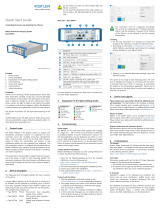
Connections/Indicators on the front panel
Connections/Indicators on the back panel
Description
1Status LED – Power
2Status LED – Ready
3Status LED – Measuring
4Status LED – Warning/Fault
5 Fiber sensor connectors - FC/APC 2.5 mm
6 CAN – D-Sub, 9Pin, male
7 Power supply – LEMO B
8 Interface to cockpit, Ethernet – RJ45
For other optional accessories see data sheet or directly
contact your Kistler salesperson.
If not in use, always seal the fiber sensor connectors
with the protective covers provided.
3. Explanation of the light emitting diodes
4. Commissioning
Power supply
For test bed applications and laboratory use, there is a 24 V
mains power supply provided with this device. Mains power
fluctuations of up to 10% of voltage input are permitted.
Ensure that you always use an adequately rated mains cable
with the included mains power supply. Although the FSI
interrogator is designed to be used with the provided power
supply, it can be used with appropriate power supplies with
voltages in a range of 9 to 30 VDC, such as those provided
in-vehicle by the vehicle power network.
Cockpit software installation
Please install cockpit on your PC running Windows 10 or
higher by performing the following steps:
1 Open the file FSIInstallation.zip from the included USB
stick or from the following link:
https://kibox-update.kistler.com/api/Deployment/
downloadFsiLatestVersion
2 The install wizard leads you through the installation process.
3 Choose your path for the installation.
4 Next update will be delivered via
Cockpit -> Notifications -> System update section.
Connect to the FSI interrogator
1 Start the Application by double clicking on the
Kistler.Cockpit.Shell.exe in your chosen FSI directory.
2 The system informs users when a new software release is
available under Notifications. Download the update first
and execute it afterwards.
3 Click on “+ Add FSI interrogator” to setup a connection.
4 In the Connection Manager you can directly select one
of the detected devices or manually configure a
connection by entering an IP address.
Quick Start Installation
Connecting the device and activating the software
FSI temperature monitoring system
Type 2549A
2549A_012-053e-10.23
Content
1. General notes
2. Device description
3. Explanation of the light emitting diodes
4. Commissioning
5. Service and support
6. Conformity
7. Safety instructions
Foreword
Thank you for choosing a Kistler quality product. Please read
these instructions carefully, so that you can take advantage
of the features of this product. The information in this
document is subject to change at any time without prior
notice. Kistler reserves the right to improve and modify the
product in accordance with technical progress without the
obligation to inform persons and organizations based on
these changes.
The present instructions are for rapid commissioning of the
device.
© 2023 Kistler Group. All rights reserved. Products of the
Kistler Group are protected by various intellectual property
rights. For more information, visit: www.kistler.com.
1. General notes
The Kistler FSI temperature monitoring system is a high-
speed optical system to map and examine thermal behavior
of powertrain components based on Fiber Segment
Interferometry (FSI). It supports multiple optical fiber sensors
for precision measurement of temperature. Each sensor fiber
can contain numerous individual measuring elements. The
data acquisition system is configured and operated with an
intuitive user interface called cockpit.
These instructions are provided to support rapid
commissioning of the device, in order to install the software,
get access to the online help, and start measuring quickly.
This document compliments the main software help and
user manual that explains all technical and functional details
in more depth.
2. Device description
The following short description explains the basic functions
of the device:
The FSI interrogator is an optoelectronic unit that illuminates
the fiber network and records the optical reflection returned
from each measuring element. To control the interrogator, a
Windows PC and an Ethernet/LAN connection is required.
A single interrogator can manage up to 4 sensor fibers, each
with up to a maximum of 22 measurement segments. Up
to 4 interrogators can be cascaded and controlled by the
cockpit software.
The FSI sensor fibers are customized to match the specific
application and calibrated individually. The sophisticated
structure of the fiber in combination with the protective
sleeve, transforms local thermal effects segment-wise,
resulting in a high-precision and quasi-distributed
thermometer.
1122334455
66
77
88
The connection must be configured accordingly. This
is done by comparing the IP addresses between FSI
interrogator and the PC. If required, the IP address of
the interrogator can be changed to suit the network
requirements.
Licensing
1 For the first connection, it is necessary to connect cockpit
to the Internet to activate the software license.
2 By clicking on the button “Activate/renew Licenses” a
Kistler website automatically synchronizes the available
License package for your FSI device.
3 Clicking on an unlocked application package opens the
default template.
The system is now ready to start measurement tasks.
Thesoftware is installed, the hardware is connected, and
thelicense is activated. Next, it is necessary to parametrize
thesystem for the measurement application. Please refer to
theuser manual in the Help Menu for advice and support on
how this can be done.
5. Service and support
Please contact your sales partner directly for additional
product information. The help function in the cockpit
software is context sensitive and is activated with the “F1”
key.
Repairs at Kistler
Repairs at the Kistler factory can be arranged via the local
sales company. Information can be found at www.kistler.com.
Please contact your sales partner directly for additional product
information.
Disposal instructions for electronic devices
Old electronics devices may not be disposed of with
household refuse/residual waste. Please return obsolete
devices to the nearest electronics disposal center for disposal
or contact your Kistler Sales Representative.
6. Conformity
CE (Europe)
The full text of the EU declaration of conformity is available
at the following Internet address:
https://www.kistler.com/de/produkt/type-2549A/
7. Safety instructions
As an environmentally aware company, Kistler does not send
out operating instructions in paper form. For this reason,
please refer to the following information regarding the
installation and operation of Kistler products:
• The safety and warning information set out below
• The specifically applicable instruction manual for
thepurchased product
Instruction manuals for each product are available on the
Kistler website and can be accessed via the type number at
www.kistler.com or with the QR code.
Paper instruction manuals can also be requested from
Kistler’s customer service or the responsible Kistler sales
department.
Instruction manuals are subject to change at any
time without advance notification, in particular
regarding equipment modifications (conversions,
retrofits etc.). Instruction manuals must be
accessed regularly on the internet for this reason.
Safety and warning information
7.1 General
Kistler offers a wide range of products in the dynamic
measurement technology sector for recording pressure,
force, torque and acceleration, designed exclusively for use
in industry and research with an emphasis on automotive
development, industrial automation and further applications
engaged in pushing back the frontiers of physical science.
These products are high-precision devices that acquire and
process data that can be transmitted electronically to other
systems.

Kistler Group
Eulachstraße 22
8408 Winterthur, Switzerland
Tel. +41 52 224 11 11
info@kistler.com www.kistler.com
2549A_012-053e-10.23 © 2023 Kistler Group
At the time of purchase, each Kistler product is compliant
with the necessary and applicable safety regulations and
all other relevant requirements. Every product is in perfect
condition with respect to safety requirements when it leaves
Kistler’s factory.
7.2 Setting up and using your product
Only qualified individuals with the necessary technical know-
how are allowed to install and operate Kistler products.
These qualified individuals must adhere to all requirements
contained in this safety and warning information and in the
applicable instruction manual for the respective product.
They must also comply with the applicable national safety
provisions for installation and operation in each case.
If a product is not installed, used or maintained in the proper
manner, this could result in serious injuries or fatal accidents
and damage to the product and its surroundings.
Please check for any damage to the packaging before
unpacking the product. Any damage found must be
reported to the shipping company and the Kistler Sales
Center or its distributor.
The delivery scope must be checked before starting to set up
the product. If a part is missing, the responsible Kistler Sales
Center or its distributor must be notified.
If the product has visible signs of damage, no longer works,
is stored for lengthy periods in unfavorable conditions
and/or was exposed to major stresses during shipping,
safe operation is no longer guaranteed and the product
must immediately be returned for repair to Kistler or the
responsible distributor.
The product may not be disassembled, opened, repaired or
otherwise modified because this may impair its operation
and, in particular, can result in electric shocks. Any attempt
to open or modify the product or to damage or remove
labels will automatically result in the voiding of all warranty
claims.
The product must not be used in potentially explosive
environments unless it is specifically designated for such use.
7.3 Product use
During storage and operation, the specifications on ambient
temperature stated in the technical data must also be
observed. The product may be permanently damaged if the
permissible ambient temperature is exceeded to a significant
extent.
The product may only be used under the specified operating
conditions; in particular, high relative air humidity and
temperature fluctuations that might result in condensation
should be avoided.
Under no circumstances must the protective ground
conductor be interrupted or rendered ineffective. Its purpose
is to provide protection against electric shocks and it must
therefore be connected to the relevant equipment.
Defective fuses must only be replaced by appropriate
substitute types with the specified current rating. “Repaired”
fuses must not be used, and fuse holders must not be short-
circuited.
Do not perform tuning, maintenance or repair work on live,
open devices.
7.4 Electromagnetic compatibility
To ensure that electromagnetic compatibility (EMC) is
maintained for the entire measuring chain, particular
attention must be paid to connection of the inputs and
outputs of the cable screen, and to the cable installation:
• Cables must not be run parallel to wiring that causes
interference.
• Only the supplied or optionally available cables must be
used.
• Please ensure a reliable connection between shielding,
connector boxes and device enclosures.
• Machinery and hardware must also comply with the EMC
standards.
7.5 Software upgrades and updates
The most recent software and firmware available on the
Kistler website must always be used.
Kistler accepts no liability whatsoever for direct or
consequential damage caused by products with outdated
firmware.
7.6 Disposal information for electrical equipment
The product must not be disposed of as
domestic waste. It must be taken instead
to a suitable collection point for the
recycling of disposable or rechargeable
batteries, electrical and electronic
equipment. Sorting, collecting and
recycling helps to preserve natural
resources and prevents impairment of human health and the
environment by hazardous substances that may be released
through the incorrect disposal of disposable or rechargeable
batteries, electrical and electronic equipment.
Please contact your Kistler Sales Center if you have any
questions about disposal.
Contact addresses and further information are available at
this internet address: www.kistler.com
7.7 Laser safety
The FSI interrogator is a Class 1 laser product
according to EN/IEC 60825-1:2014. Avoid
long-term viewing of the output, especially
using optical viewing instruments. Do not
attempt to operate the device in a disassembled
state or otherwise access the laser directly, as
this may result in hazardous radiation exposure.
/
