Teach Logic IRP-1120/CS4 Owner's manual

Category
Musical Equipment
Type
Owner's manual
Amplier
Audio Mixer
Infrared Microphone Receiver
IMA-120 MatrixTM
CLASSROOM AUDIO SYSTEM
INSTALLER AND OPERATIONS MANUAL
rev20200324
P/N UMM-120
notes
Date of Purchase:
Model Number:
Serial Number:
Notes:
2
contact
If you should encounter some
unresolved issue, please
contact TeachLogic customer
service department for further
assistance.
welcome
Congratulations on the purchase of your new TeachLogic system.
You can be assured that this fullls all specications and was
produced to very high quality control standards. TeachLogic
incorporates the latest state of the art technology, employs the
most advanced manufacturing methodology and uses only
premium quality components to assure many years of reliable
performance. We appreciate your condence by your selection
of our product. It is TeachLogic’s intent to uphold that condence
by providing factory assistance and dealer support.
We hope you will take the time to review this manual to familiarize
yourself with the product operation and features. This manual
will help you learn to use and gain the maximum benet of the
system.
TeachLogic LLC
Longmont, Colorado, USA
teachlogic.com
1-760-631-7800
support@teachlogic.com
www.teachlogic.com
3
THANK YOU
safety instructions
Read Instructions
All safety and operation instructions should be read before
operating this TeachLogic product.
Retain Instructions
Safety and operating instructions should be kept for future
reference.
Water & Moisture
This product should not be operated near water.
Heat Environment
Do not subject this product to excessive heat conditions.
Power Source
This product must be connected to an AC power source per
the voltage input specied and marked on the power supply.
Power Cord Caution
Power cable should be routed clear of foot trac and
supported clear of kinking or abrasion.
Object Protection
Locate the operating unit so it will not be subjected to falling
objects or water entry.
Internal Service
User should not attempt to service this product. All internal
service must be accomplished by a qualied technician.
Electric Shock
Do not adapt or modify the AC power plug thus lifting the
earth ground connection.
Recycle—Do not dispose rechar-
geable batteries in trash. Actually
it is unlawful to do so in CA, NY &
ME.
Contact: Earth911.com
1-800-CLEANUP
Save our resources and don’t
contaminate.
Go Green
caution
certications
TeachLogic systems are
manufactured using lead-
free processes and are free
of materials harmful to the
environment. They conform
to the most stringent new
European guidelines for
consumer products (RoHS).
4
Caution: To reduce the risk of electric
shock DO NOT remove cover or back.
No user serviceable parts inside
Refer servicing to qualied personnel
5
table of contents
About Infrared
System Overview
Wiring Diagram
Infrared Microphones
Components: Drop-in Charger BRC-60/Ceiling Sensor ICS-55
Installation of Ceiling Sensor
Installation of Ceiling Speakers
Installation of Wall Mount Speakers
Final Connection of Speakers
Page Mute/Pass Through
CPS-120/CPR-125 Remote Control Panel
RS-232 Features / RS-232 Codes
Bluetooth
Security Alert Feature
System Operation
Troubleshooting
Five Year Limited Warranty
6
7
8
9-10
11
12
13-14
15
16
17
18-19
20
21
22
23
24
25
6
a brief word about infrared
Infrared is a light ray that is below the visible spectrum, just like sound extends beyond your hearing
ability. An example of infrared transmission is the remote control for your TV set. When a button is
pressed, a beam of infrared light is emitted by a Light Emitting Diode (LED) from the remote control. It is
detected by a receiving diode in your TV set.
When you press a certain command on your control, the internal electronics cause the infrared light to
icker in a programmed sequential pattern (called modulating the light beam). The modulated infrared
beam is detected by the receiving diode and is electronically decoded. The decoded signal activates the
circuitry to perform the command function on your TV set.
So how does this apply to the infrared communication system you are about to start using? The
microphone/transmitter has several Light Emitting Diodes (LED) that emit infrared light beams to the
sensor located in the corner of the room.
When you talk into the microphone, the microphone element modulates the light beam, causing it to
icker in sync with your speech. The sensor detects the sequential signal and the electronic circuitry in
the amplier converts that sequential signal into a line level analog audio signal. Now that audio signal
can be fed into an amplier. The amplier magnies the electronic signal and sends it to the speakers.
This causes the speaker cone to move in sync with your voice. The speaker replicates your voice and
disperses your voice evenly throughout the room.
IR transmission
The IR transmitter
transmits directly to the
sensor. However; due
to the strength of the IR
transmitter, the infrared
signal will bounce o the
walls, ceiling and oor for
reception thus providing
continuous connectivity
throughout the room.
Benet: total freedom
of movement within the
room with no restriction
of orientation.
Infrared will not
penetrate a solid surface
thus preventing any
transmission from
going out of the room.
What’s said in the
room, stays in the
room”.
7
system overview
The Matrix is an amplier, audio mixer, and infrared wireless microphone receiver in one. It is the hub of
the classroom audio system as various media inputs can be connected to it, so that all classroom audio
can be amplied and distributed clearly through the speakers. The addition of microphones provides
voice reinforcement for the teacher and students alike.
The Matrix system is comprised of a microphone / transmitter, either the Sapphire (IRT-60), or Handheld
(IRH-35) for voice transmission to a ceiling sensor (ICS-55) that sends the signal to the receiver /
amplier (IMA-120). The receiver/amplier processes the signal and produces an analog signal of your
voice for output to the sound eld speaker system.
1. Power on/o Indicator
2. Page sensitivity control
3. Bass/Treble equalizer ±12 dB
4. CH 1 Mic Volume Control
5. CH 2 Mic Volume Control
6. Line 1 Volume Control
7. Line 2 Volume Control
8. Line Out Volume Control
9. Line 1 Input (3.5mm)
10. Line 2 Input (3.5mm)
11. Line Output (3.5mm)
12 3 4 5 6 7 8 9 10 11
12 13 14 15 16 17 18 19 20
17. Security Alert - Com | N.O.| N.C.
18. Impedence selector 25V, 70V, 100V
19. Page Mute Input - 2-pin Phoenix
20. Speaker Output - Two Channel, 4-pin
Phoenix connector
12. Power Input: 19 VDC 3.4A
13. RJ-45 Control Panel Jack
14. RS-232 Switch (O/On)
15. UPGRADE input Micro USB
16. Two Sensor Inputs (RCA)
8
CEILING/WALL MOUNT SPEAKERS
CEILING SENSOR(S)
From page system
CPS-120/CPR-125
REMOTE
CONTROL PANEL
UP TO 2 MEDIA DEVICES
LESSON CAPTURE
RECORDER
Wall mounted
call button
THIRD PARTY
INTERCOM/PAGING
SPEAKER
3RD PARTY INTERCOM/
PAGING SYSTEM WALL
PANEL
Emergency
Normal Output to front oce
intercom panel via
existing intercom cabling
TeachLogic Matrix™ Wiring Diagram
ASSISTIVE LISTENING
DEVICE (3.5 mm
analog output)
wiring diagram
9
infrared microphones
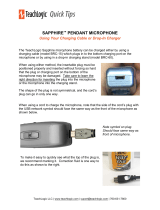
The infrared microphone/transmitter is comprised of a microphone input, signal processing circuits
and several emitting diodes that transmit the vocal signal to the sensor.
The microphone/transmitter can be the Sapphire or Handheld. The rechargeable batteries will provide
6–8 hours of service per charge. Place the microphone/transmitter in the charger for overnight charge
and it will be ready for another day’s use.
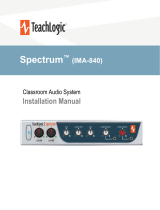
The drop-in battery chargers are specically designed to recharge lithium & NiMH batteries at an
optimum rate for Matrixum operating capacity and extended service life. Charger will automatically
start charging the batteries upon insertion and will shift to a maintenance charge when batteries are
fully charged.
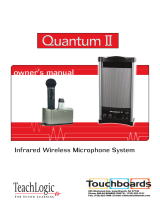
The Sapphire’s vocal clarity is unsurpassed. Its high
level output is achieved by the unidirectional (Cardioid)
microphone and a unique free air suspension system. With
a built-in breath lter, the Sapphire can function as a pass
around hand mic.
The strategic alignment of the emitting diodes assures
reliable connectivity throughout the room without static or
drop out.
With a tap on the power button, the microphone is muted
for private conversation—tap again to restore to normal
operation. The auxiliary input allows wireless playback of
your personal music device through the Sapphire. A three
position slide switch provides selection of normal, medium
(-3 dB), or low (-6 dB) microphone sensitivity.
features
Elegant design
Only 1.4 oz. including battery
Long life Lithium Ion battery
Rechargeable via USB cable
Battery level indicator – Back
light under power switch
Momentary mute button,
backlight blinks in mute mode
Push “on/o” power
Channel “A” or “B” selectable
Three level microphone vol-
ume switch
3 voice sensitivity settings
(Normal, -3dB, -6dB)
Auxiliary input (3.5mm) for
headset or music device
Wear with a lanyard or slide
directly on neckline collar
(IRT-60) sapphire transmitter
10
IRH-35 handheld transmitter
The Handheld Microphone Transmitter (IRH-35) is most
applicable for student use or direct presentation. It has an “on/
o” switch and a battery level indicator LED; Green=useable
charge, Red=low battery. The transmitter has 10 emitting
diodes: 8 around the bottom of the handle, and 2 toward the
top of the handle. The metal housing provides low handling
noise and insures durable longevity.
features
Condenser microphone
element
Power “on/o” switch
Battery level indicator—LED
Channel “A” or “B” selectable
10 high-power emitting diodes
Diodes at top and bottom of
handle for increased
Coverage (2 Top aimed out, 6
Bottom 360°, 2
Bottom aimed down)
360º IR radiation for assured
connectivity
Two “AA”, Duracell,
rechargeable NiMH batteries
IRT-60 remote control features
1. Moving the priority switch Up/Down will control the volume of
the line inputs.
2. A momentary tap of the priority switch will duck down the line
inputs 15dB. The receiver front panel power switch changes to
a blinking PURPLE. A second tap will restore line input back to
normal.
3. Hold in priority switch for 4 seconds closes the contact
closure on the Security Alert output. The receivers front panel
power switch changes to blinking GREEN. Holding the button
down for another 4 sec. returns the contact to normal.
infrared microphones
11
BRC-60 drop-in battery charger
This stylish desktop drop-in charging station makes it convenient
and easy to recharge both Sapphire Pendant and Handheld
Microphones. Charge one IRH-35 handheld transmitter and up
to two IRT-60 Sapphire transmitters simultaneously. Charging
indicator lights illuminate Red when charging, and Green when
fully charged. The power LED illuminates Blue when plugged in.
ICS-55 ceiling sensor
sensor cable
The ceiling sensor is the preferred infrared sensor for optimum
performance. This is the unit that needs to be installed on the
ceiling. It comes with a mounting/support bracket and 50 feet of
plenum rated cable with RCA connector on each end. The ideal
location for the dome sensor would be in the center of the ceiling.
This will provide a clear signal path for the IR transmission from
the transmitter to the dome sensor without obstruction. In addition,
you will have 360° coverage and will minimize the transmission
distance for more reliable performance. It collects the infrared
transmission signal via 6 large detecting diodes.
A cable connects the sensor to the receiver. The cable is dual-
shielded with a male RCA connector on each end and is plenum
rated.
Green light indicates that
the sensor is receiving
power from the receiver.
power “on” LED
components
12
The ideal location for the ceiling sensor is in the center of the ceiling. This will provide a clear signal path
for the IR transmission from the transmitter to the dome sensor without obstruction. In addition, you will
have 360º coverage and will minimize the transmission distance for more reliable performance.
Installation 1 - Attach to T-bar Rail
Installation 2 - Attach to wood surface Installation 3 - Attach to drywall or concrete
surface
ceiling sensor installation
13
speaker installation
installing planning
Front of Room
Receiver
Amplifier
Ceiling Sensor
Wall Speakers
Front of Room
Receiver
Amplifier
Ceiling Sensor
r
r
Wall Speakers
Front of Room
Ceiling Sensor
Listening Area
List
A
rea
Ceiling Speakers
Front of Room
Ceiling Sensor
Listening Area
Ceiling Speakers
Amplier/Receiver: Choose location the based on accessibility requirements and wiring
constraints for power, speakers, and audio devices.
Ceiling Sensor: Locate in the center of the ceiling; maintain line of sight; keep away from direct
light and electrical interference.
Speakers: Mark location for wall mount vs. ceiling mount, and conrm wiring run to the amplier.
Ensure speakers evenly cover the listening area.
Integrations/Connections: Conrm location of other systems you plan to connect to the amplier
such as audio devices, intercom connections, re alarm, noting how the wiring needs to run.
Microphones/Charger: Conrm microphone charging location for daily use/charging.
ceiling speaker installation
1. Determine the listening area based on where students are seated.
2. Divide listening area into quadrants.
3. Locate and identify the center most tile in each quadrant to ensure even distribution of sound.
4. Lay ceiling tile face down on clean at surface.
5. Lay tile bridge on ceiling tile and center it.
6. Trace and cut the large hole using a keyhole or drywall saw.
The IMA-120 has two channels of amplied audio, rated for a minimum 4-ohm speaker load (two
8-ohm speakers each). There is one blue phoenix style speaker connector on the back panel, provid-
ing one pair of speaker terminals. When using 4 speakers they must be wired in parallel.
Figure 2: Cutting the Tile
Tile Bridge
Back Side of
Ceiling Tile
Cut Out Area
SP-628
14
7. Strip the speaker cable ends, approx. ½".
8. Route speaker wire from speaker opening to amplier.
9. Reinstall ceiling tile with tile bridge in place above the hole.
10. Pull speaker cable back down through speaker hole.
11. With a pointed tool or paper clip, lift up and remove speaker grill and set aside to avoid damage
12. Set speaker on top of ladder and connect speaker wire.
13. Observe speaker polarity, connect Red wire to (+) terminal and black wire to the (C) terminal.
14. For locations where earthquake or a safety restraint is required, make the attachment to the
speaker and ensure it’s secure.
15. With the mounting clamps folded back, position speaker into speaker hole.
16. With a #2 Phillips screwdriver, tighten the quick clamps.
speaker installation
16. Reinstall speaker grille and remove any soil or ngerprints.
17. Repeat steps 7-16 for other speakers.
18. See “nal connection” section to nish installation.
Mounting Screws
1. Lay ceiling tile face down on clean at surface.
2. Lay the SP-628L on the tile with at end (the opposite end of the integrated T-bar) ush with
the end of the tile.
3. Mark opposite end where you will make the cut. Mark the two opposite ends of the tile.
4. Take care to mark where the SP-628L integrated T-bar connects to the assebly.
5. Connect the marks with a level or at object to ensure you draw a straing line across the tile.
6. Cut the tile using a drywall saw.
7. Set speaker on top of ladder and connect speaker wire.
8. Place speaker in the ceiling ensuring it’s secure.
9. For locations where earthquake or a safety restraint is required, make the attachment to the
speaker and ensure it’s secure.
10. Replace ceiling tile.
11. See “nal connection” section to nish installation.
SP-628L
9. Strip speaker cable ends ½” and connect to speaker.
10. Observe speaker polarity: Connect (+) wire (with printed writing) to (+) terminal and (-) wire
(unprinted & textured) to the (-) terminal.
11. Route speaker cable to the receiver/amplier in a safe, least visible, tidy manner.
12. See “nal connection” section to nish installation. 15
speaker installation
installing SP-2000 wall mount speakers
4. Install the mounting brackets on wall in the vertical (up/down) orientation.
5. Mount brackets using the appropriate hardware
6. Insert speaker with the tweeter in upper position.
7. Secure speaker in bracket with the hand fasteners.
8. Orient each speaker toward the center of that half of the listening area and tighten fasteners.
20˚
33˚
45˚
1. First observe the shape of the room: ceiling height, door locations, windows, mounting
surface, and seating area.
2. Ordinary installation would be to locate the speakers on each side wall approximately
even with the front row of listeners.
3. It is recommended to mount the speakers a minimum of 6 feet above the oor.
Note: In a room with 10’ ceilings, a mounting height of 9.5’ is ideal.
Front of Room
Receiver
Amplifier
Ceiling Sensor
Wall Speakers
Front of Room
Receiver
Amplifier
Ceiling Sensor
r
r
Wall Speakers
Front of Room
Ceiling Sensor
Listening Area
List
A
rea
Ceiling Speakers
Front of Room
Ceiling Sensor
Listening Area
Ceiling Speakers
nal connection of the system
With receiver/amplier located, speaker and sensor cables neatly routed, we are ready to complete the
installation.
1. Cut the speaker wire to the appropriate length
2. Strip about 3/8” o the end of each speaker wire.
3. Twist the wire and if you have a soldering iron, tin the wire ends
4. Unplug the phoenix connector from amplier. Reference amplier insert diagram on amplier
(Figure H) (+) wire (with printed writing) into either outside (+) terminal.
5. Plug the other (-) wire into center (-).
speaker installation
5. Tighten set screws.
6. Repeat for other pair and insert plug rmly into speaker output receptacle.
7. Plug amplier power supply into AC outlet.
8. Connect audio sources and set output to desired levels.
Figure H
Speaker Output Phoenix Connector
16
17
page mute/pass through
The Page Mute feature allows you to connect the TeachLogic amplier to the school paging/intercom
system for muting purposes. A simple connection between the in-classroom paging speaker (typically
25v, 70v or 100v) and the TeachLogic page input will mute all the inputs and pass the page to the
speakers connected to the TeachLogic amplier. System resumes audio (slowly ramping up volume)
6 seconds after no additional page signal is detected.
KEY SPECS (based on 25 V paging systems)
Page signal required to activate mute function: 6.0 V
The impedance of the IMA-120 is 160 Kohms in the 25V switch position, and 180 Kohms in the 75
and 100V switch positions.
Power draw = 0.004 Watts or less (power = voltage*voltage/impedance, or 25*25/160,000).
CONNECTION
1. Tap/Splice page speaker’s wire and connect to our amp via 2-pin Phoenix connector.
2. Determine the signal level of the paging system (25v, 70v, or 100v) and set the slide switch to the
appropriate speaker level setting.
PASS-THRU FUNCTION
The amplier will pass the paging audio through the classroom audio speaker(s) connected to it.
Note that you may use the classroom audio system speakers in addition to or in lieu of dedicated
paging speaker.*
* IMA-120 Matrix only passes page audio through speakers when the amplier is powered.
Figure I: impedence selector /
page input Phoenix Connector
Figure J: page sensitivity
control
3. With the TeachLogic amplier turned ON, send a page signal through the page input.
4. Adjust the page input SENSITIVITY control, located on front panel, so that an incoming page/
intercom signal will override any audio (mics, line, etc) plugged into the TeachLogic amplier.
18
CPS-120/CPR-125 controller
Audio levels very often need to be
adjusted when switching from computer
audio to DVD players and other audio
sources.
Such operations as level UP, DOWN
and MUTE are easily accomplished via
the eight button controller and touch
rotary dial, as shown here. This allows
the receiver/amplier to be placed in an
area or compartment that is not easily
assessed by the user.
No set up is required for these
touch panels to operate. They are
preprogrammed right out of the box.
remote control of audio inputs
CPR-125
The CPR-125 has an additional RJ-45 connection to connect to an intercom system. This colocates the
audio controls with the wall-mounted paging buttons into one convenient panel.
IMPORTANT
When any
remote panel
is connected,
RS-232 switch
must be in "ON"
position.
When panel is
not connected,
RS-232 switch
must be in "OFF"
position for
amplier controls
to function.
19
remote control of audio inputs
1. Connect cable between amplier RJ-45 and remote touch panel RJ-45. Please note that the
the CAT5 cable between Matrix and controller should be no more than 50 ft (15 m).
2. Place RS-232 switch in the "ON" position to activate touch panel.
3. When wall plate power is on, the LCD screen will illuminate the logo.
4. The LCD screen will illuminate in two brightness levels, DIM (power save mode) and ON (full
brightness).
5. To activate the screen press any button to turn the screen ON.
6. When the LCD screen light is ON, you can press any of the eight available input
source buttons to adjust the volume.
CPS-120/CPR-125 panel operation
EXAMPLE:
Aux input volume adjust:
**Please note that you can only adjust the
volumes when the screen light is ON**
1. Depress AUX button on touch control
panel. The AUX and level indicator will
appear in the LCD window.
2. Touch the rotary control in a clock wise
direction to increase volume.
Volume Up
3. Touch the rotary control in a counter
clock wise direction to decrease volume.
Volume Down
4. MUTE control: Press the "MUTE" button
- The screen indicates "AUX MUTE" and
starts to blink.
Press the "MUTE" button again to return
to the present volume.
volume control
AUX
20
remote control of audio inputs: RS-232
RS-232
The IMA-120 Matrix can accomodate 3rd party remote control panels that connect via RJ-45. Follow
the pin out digram and Hex code chart to ensure your control panel is wired and programmed properly.
IMPORTANT
When any
remote panel
is connected,
RS-232 switch
must be in "ON"
position.
When panel is
not connected,
RS-232 switch
must be in "OFF"
position for
amplier controls
to function.
RS-232 codes
Baud Rate : 9600
Parity Bit : NONE
Data Bit : 8
Stop Bit : 1
Function HEX
Power:TOGGLE 4c 69 6e 6b 78 3a 50 6f 77 65 72 3a 54 4F 47 47 4C 45 0D
Gain ACH UP 4c 69 6e 6b 78 3a 47 61 69 6e 3a 41 43 48 3a 55 50 0D
Gain ACH DOWN 4c 69 6e 6b 78 3a 47 61 69 6e 3a 41 43 48 3a 44 4f 57 4e 0D
Gain ACH MUTE 4c 69 6e 6b 78 3a 47 61 69 6e 3a 41 43 48 3a 4d 55 54 45 0D
Gain BCH UP 4c 69 6e 6b 78 3a 47 61 69 6e 3a 42 43 48 3a 55 50 0D
Gain BCH DOWN 4c 69 6e 6b 78 3a 47 61 69 6e 3a 42 43 48 3a 44 4f 57 4e 0D
Gain BCH MUTE 4c 69 6e 6b 78 3a 47 61 69 6e 3a 42 43 48 3a 4d 55 54 45 0D
Gain LINE IN1 UP 4c 69 6e 6b 78 3a 47 61 69 6e 3a 4c 49 31 3a 55 50 0D
Gain LINE IN1 DOWN 4c 69 6e 6b 78 3a 47 61 69 6e 3a 4c 49 31 3a 44 4f 57 4e 0D
Gain LINE IN1 MUTE 4c 69 6e 6b 78 3a 47 61 69 6e 3a 4c 49 31 3a 4d 55 54 45 0D
Gain LINE IN2 UP 4c 69 6e 6b 78 3a 47 61 69 6e 3a 4c 49 32 3a 55 50 0D
Gain LINE IN2 DOWN 4c 69 6e 6b 78 3a 47 61 69 6e 3a 4c 49 32 3a 44 4f 57 4e 0D
Gain LINE IN2 MUTE 4c 69 6e 6b 78 3a 47 61 69 6e 3a 4c 49 32 3a 4d 55 54 45 0D
Gain LINE OUT UP 4c 69 6e 6b 78 3a 47 61 69 6e 3a 4c 45 4f 3a 55 50 0D
Gain LINE OUT DOWN 4c 69 6e 6b 78 3a 47 61 69 6e 3a 4c 45 4f 3a 44 4f 57 4e 0D
Gain LINE OUT MUTE 4c 69 6e 6b 78 3a 47 61 69 6e 3a 4c 45 4f 3a 4d 55 54 45 0D
  • Page 1 1
  • Page 2 2
  • Page 3 3
  • Page 4 4
  • Page 5 5
  • Page 6 6
  • Page 7 7
  • Page 8 8
  • Page 9 9
  • Page 10 10
  • Page 11 11
  • Page 12 12
  • Page 13 13
  • Page 14 14
  • Page 15 15
  • Page 16 16
  • Page 17 17
  • Page 18 18
  • Page 19 19
  • Page 20 20
  • Page 21 21
  • Page 22 22
  • Page 23 23
  • Page 24 24
  • Page 25 25
  • Page 26 26

Teach Logic IRP-1120/CS4 Owner's manual

Category
Musical Equipment
Type
Owner's manual

Ask a question and I''ll find the answer in the document

Finding information in a document is now easier with AI