Page is loading ...

1998-99 ENGINES
4.6L V8 - VIN W & 6
ENGINE IDENTIFICATION
Engine is identified by eighth character of Vehicle Identification Number (VIN). See
ENGINE
IDENTIFICATION CODES
table. VIN is located on top of instrument panel, near lower left corner of
windshield. VIN is also stamped on Vehicle Certification (VC) label mounted on left door pillar.
Engine code labels are located in engine compartment, in front of radiator and on right valve cover. Label
contains engine calibration number, engine build date, engine plant code and engine code.
Emission calibration number label is located on upper radiator shield. This label identifies engine calibration
number, engine code number and revision level. Numbers from labels are required when ordering replacement
p
arts.
ENGINE IDENTIFICATION CODES
Windsor and Romeo engine plants are producing the 4.6L engine. There are several differences between these
engines and many parts are not interchangeable.
The best way to determine manufacturer is by the VIN number. VIN W is a Romeo engine. VIN 6 is Windsor
engine. There are a couple external differences. The right valve cover on Windsor engine has 14 bolts, Romeo
engine has 11 bolts. Also on Windsor engine there is a W stamped on each valve cover in area of camshaft
sprocket.
ADJUSTMENTS
VALVE CLEARANCE ADJUSTMENT
Hydraulic valve lash adjusters are used. No valve adjustment is required.
TROUBLE SHOOTING
REMOVAL & INSTALLATION
Engine Type Fuel System Engine Plant VIN Code
4.6L SOHC SFI Romeo W
4.6L SOHC SFI Windsor 6
NOTE: To trouble shoot mechanical engine components, see ENGINE MECHANICAL in
BASIC TROUBLE SHOOTING article in GENERAL INFORMATION.
CAUTION: When battery is disconnected, vehicle computer and memory systems
1999 Ford Pickup F350 Super Duty
1998-99 ENGINES 4.6L V8 - VIN W & 6
1999 Ford Pickup F350 Super Duty
1998-99 ENGINES 4.6L V8 - VIN W & 6
Helpmelearn Repair Manuals
Friday, November 24, 2006 4:21:22 PM Page 1 © 2004 Mitchell Repair Information Company, LLC.
Helpmelearn Repair Manuals
Friday, November 24, 2006 4:21:31 PM Page 1 © 2004 Mitchell Repair Information Company, LLC.

FUEL PRESSURE RELEASE & FUEL LINE CONNECTIONS
1. Remove fuel cap to release fuel tank pressure. Connect EFI Pressure Gauge (T80L-9974-B) to relief
valve on right rear corner of fuel rail. Release pressure using valve on pressure gauge.
2. Before disconnecting fuel lines, disconnect negative battery cable. To disconnect fuel lines, remove
retaining clip from outside of fuel line coupling.
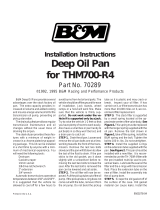
3. Install Spring Lock Coupling Remover (D87L-9280-A) for 3/8" line or (D87L-9280-B) for 1/2" line on
fuel line coupling so it enters cage opening. See
Fig. 1
.
4. Push spring lock coupling remover into cage opening to release female fitting from garter spring. Pull
couplings apart. Remove spring lock coupling remover.
5. When installing fuel lines, fit NEW fuel resistant "O" rings (Brown) on fuel lines. Before installing,
lightly coat "O" rings with clean engine oil. Clean fittings, and replace garter spring (if necessary).
6. Install female fitting to male fitting and push until garter spring snaps over flared end of female fitting.
Ensure lines lock together and garter spring is over female fitting flared end.
7. Install retaining clip. Install Black retaining clip on fuel supply line and Gray clip on fuel return line.
Ensure horseshoe
p
ortion of cli
p
is over cou
p
lin
g
. DO NOT install retainin
g
cli
p
over rubber fuel line.
may lose memory data. Driveability problems may exist until computer
systems have completed a relearn cycle. See COMPUTER RELEARN
PROCEDURES article in GENERAL INFORMATION before disconnecting
battery.
NOTE: For reassembly reference, label all electrical connectors, vacuum hoses and
fuel lines before removal. Place mating marks on engine hood and other major
assemblies before removal.
WARNING: Fuel system is under pressure. Release pressure before servicing fuel
system components.
1999 Ford Pickup F350 Super Duty
1998-99 ENGINES 4.6L V8 - VIN W & 6
Helpmelearn Repair Manuals
Friday, November 24, 2006 4:21:22 PM Page 2 © 2004 Mitchell Repair Information Company, LLC.

Fig. 1: Disconnecting Fuel Lines
Courtesy of FORD MOTOR CO.
ENGINE
Removal (Expedition, Navigator & F150/250 Pickup)
1. Disconnect negative battery cable. Remove hood. Drain cooling system. Remove radiator. Discharge A/C
system using approved refrigerant recovery/recycling equipment. Release fuel pressure and disconnect
fuel lines. See
FUEL PRESSURE RELEASE & FUEL LINE CONNECTIONS
.
2. On Expedition and Navigator, remove air conditioning condenser and EGR manifold tube. Unclip mega
fuse holders from junction block bracket. Disconnect starter relay cables.
3. On all models, remove upper intake manifold. See
INTAKE MANIFOLD
. Remove bulkhead connector
cover. Disconnect necessary grounds and harness connectors. Disconnect necessary water and vacuum
connections. Unbolt power steering bracket, and position reservoir and bracket assembly aside. Remove
ignition coils and brackets.
4. Raise and su
pp
ort vehicle. Remove starter. Remove A/C com
p
ressor. Remove transmission cooler line
WARNING: Ensure air suspension system is shut off prior to hoisting, jacking or
towing an air suspension vehicle. Air suspension switch is located
behind right kick panel. Failure to do so can result in inflation or deflation
of air springs, which may cause vehicle to shift during servicing.
1999 Ford Pickup F350 Super Duty
1998-99 ENGINES 4.6L V8 - VIN W & 6
Helpmelearn Repair Manuals
Friday, November 24, 2006 4:21:23 PM Page 3 © 2004 Mitchell Repair Information Company, LLC.

from block mounted clip. Remove transmission inspection cover, torque converter bolts and
transmission-to engine bolts. Remove power steering retaining bolts and position power steering pump
aside.
5. Disconnect dual-converter "Y" pipe from exhaust manifolds, and position aside. Remove right and left
engine mount bolts. Lower vehicle and support transmission. Remove engine from vehicle.
Removal (E150)
1. Disconnect negative battery cable(s). Discharge A/C system using approved refrigerant
recovery/recycling equipment. Release fuel pressure and disconnect fuel lines. See
FUEL PRESSURE
RELEASE & FUEL LINE CONNECTIONS
.
2. Disconnect necessary harness and ground connections. Remove intake manifold. See
INTAKE
MANIFOLD
. Remove air deflector, radiator grille, radiator grille open panel and upper and lower core
supports. Remove radiator, fan shroud and cooling fan.
3. Remove headlight and side marker assemblies. Remove A/C condenser. Remove accessory drive belt.
Drain power steering fluid by disconnecting reservoir hose at power steering pump. Disconnect high
pressure hose at power steering pump. Remove lower radiator hose. Disconnect suction hose at receiver-
drier.
4. Raise and support vehicle. Disconnect dual-converter "Y" pipe at exhaust manifold. Drain engine oil and
remove oil filter. Remove oil cooler. Remove starter. Remove transmission-to-engine bolts.
5. Remove and discard torque converter nuts. Remove engine mount-to-subframe nuts. Lower vehicle.
Remove transmission oil filler tube. Support transmission. Remove engine from vehicle.
Installation (All Models)
1. To install, reverse removal procedure. Tighten all bolts to specification. See
TORQUE
SPECIFICATIONS
.
2. When installing fuel lines, fit NEW fuel resistant "O" rings (Brown) on fuel lines. Lightly coat "O" rings
with clean engine oil before installing. Clean fittings, and replace garter spring (if necessary).
3. Adjust all control cables and fluid levels. Refill cooling system. Evacuate and recharge A/C system.
INTAKE MANIFOLD
Removal (Upper & Lower)
1. Disconnect negative battery cable(s). Remove engine cover. Release fuel pressure and disconnect fuel
lines. See
FUEL PRESSURE RELEASE & FUEL LINE CONNECTIONS
. Drain cooling system.
Disconnect upper radiator hose from thermostat housing. Remove air cleaner and outlet tube assembly.
Remove throttle body. Remove EGR manifold tube.
2. Disconnect necessary vacuum and water connections. Disconnect necessary wiring connections. Remove
spark plug wires. Remove accessory drive belt. Remove alternator. Remove upper intake manifold-to-
head retaining bolts in reverse order of tightening sequence. See
Fig. 3
.
3. Lift upper and lower intake manifold assembly. Disconnect electrical connector at manifold tuning valve,
and remove intake manifold assembly from vehicle. Remove upper intake manifold-to-lower intake
manifold mountin
g
bolts. Remove
p
ush
p
in retainer from front of manifold insulator. Se
p
arate manifold
1999 Ford Pickup F350 Super Duty
1998-99 ENGINES 4.6L V8 - VIN W & 6
Helpmelearn Repair Manuals
Friday, November 24, 2006 4:21:23 PM Page 4 © 2004 Mitchell Repair Information Company, LLC.

insulator from lower intake manifold. See
Fig. 2
. Separate upper and lower intake manifolds.
Installation
1. To install, reverse removal procedure. Use NEW gaskets and "O" rings. Lubricate fuel injector "O" rings
with Light Grade Oil (ESE-M2C39-F) before installing.
2.
Ensure alignment tabs on intake manifold gaskets align with holes in cylinder head. Tighten upper intake
manifold to lower intake manifold bolts to specification in sequence. See
Fig. 3
. Tighten upper intake
manifold-to-head bolts to specification in sequence. See
Fig. 4
. See
TORQUE SPECIFICATIONS
.
3. When installing fuel lines, fit NEW fuel resistant "O" rings (Brown) on fuel lines. Lightly coat "O" rings
with clean engine oil before installing. Clean fittings, and replace garter spring (if necessary).
4. To install remaining components, reverse removal procedure. Adjust all control cables and fluid levels.
Refill cooling system. When installing spark plug wires, ensure wires are in correct position on coils. See
a
pp
ro
p
riate SERVICE & ADJUSTMENT SPECIFICATIONS article in ENGINE PERFORMANCE.
CAUTION: Intake manifold bolts must be retightened to specification after
engine has reached normal operating temperature.
1999 Ford Pickup F350 Super Duty
1998-99 ENGINES 4.6L V8 - VIN W & 6
Helpmelearn Repair Manuals
Friday, November 24, 2006 4:21:23 PM Page 5 © 2004 Mitchell Repair Information Company, LLC.

Fig. 2: Exploded View Of Upper & Lower Intake Manifold
Courtes
y
of FORD MOTOR CO.
1999 Ford Pickup F350 Super Duty
1998-99 ENGINES 4.6L V8 - VIN W & 6
Helpmelearn Repair Manuals
Friday, November 24, 2006 4:21:23 PM Page 6 © 2004 Mitchell Repair Information Company, LLC.

Fig. 3: Upper Intake Manifold-To-Lower Intake Manifold Bolt Tightening Sequence
Courtes
y
of FORD MOTOR CO.
1999 Ford Pickup F350 Super Duty
1998-99 ENGINES 4.6L V8 - VIN W & 6
Helpmelearn Repair Manuals
Friday, November 24, 2006 4:21:23 PM Page 7 © 2004 Mitchell Repair Information Company, LLC.

Fig. 4: Upper Intake Manifold-To-Head Bolt Tightening Sequence
Courtesy of FORD MOTOR CO.
EXHAUST MANIFOLD
Removal (All Models)
Raise and support vehicle. Remove front fender splash shield. If removing left side, remove EGR manifold tube
and brake vacuum booster hose bracket. On either side, disconnect exhaust manifold flange. Remove exhaust
manifold retainin
g
nuts in reverse order of ti
g
htenin
g
se
q
uence. See
Fi
g
. 5
. Remove exhaust manifold and
WARNING: Ensure air suspension system is shut off prior to hoisting, jacking or
towing an air suspension vehicle. Air suspension switch is located
behind right kick panel. Failure to do so can result in inflation or deflation
of air springs, which may cause vehicle to shift during servicing.
1999 Ford Pickup F350 Super Duty
1998-99 ENGINES 4.6L V8 - VIN W & 6
Helpmelearn Repair Manuals
Friday, November 24, 2006 4:21:23 PM Page 8 © 2004 Mitchell Repair Information Company, LLC.

gasket.
Installation
To install, reverse removal procedure. Tighten exhaust manifold nuts to specification in sequence. See
Fig. 5
.
See
TORQUE SPECIFICATIONS
.
Fig. 5: Exhaust Manifold Bolt Tightening Sequence
Courtesy of FORD MOTOR CO.
CYLINDER HEAD
Removal
1. On 1998 models, disconnect negative battery cable(s). Remove intake manifold. See
INTAKE
MANIFOLD
. On 1999 models, remove engine. See
ENGINE
. On all models, remove exhaust
manifold. See
EXHAUST MANIFOLD
.
2. Remove timing chains. See
TIMING CHAINS
. On 1998 models, disconnect heater hoses. On 1998
Expedition, F150, F250 and Navigator, remove heater pipe-to-engine mounting studs. Remove heater
pipe and discard "O" ring. On all models, remove cylinder head bolts in sequence. See
Fig. 6
or
Fig. 7
.
Remove cylinder head and gasket.
Inspection
Check cylinder head for warpage, cracks and damage. Maximum warpage information is not available from
manufacturer.
Installation
CAUTION: If cylinder head-to-block surface refinishing is necessary, DO NOT remove
more than .010" (.25 mm) from cylinder head surface.
1999 Ford Pickup F350 Super Duty
1998-99 ENGINES 4.6L V8 - VIN W & 6
Helpmelearn Repair Manuals
Friday, November 24, 2006 4:21:23 PM Page 9 © 2004 Mitchell Repair Information Company, LLC.

1. Ensure proper gaskets are installed. Right and left cylinder head gaskets are not interchangeable. Rotate
crankshaft 90 degrees counterclockwise from vertical position. See STEP 1 in illustration. See
Fig. 9
.
Ensure no piston is at TDC.
2.
Coat bolt head-to-cylinder head surfaces with engine oil. DO NOT oil threads of cylinder head bolts.
Ensure rear cylinder head bolts are installed in cylinder head and secured by rubber bands before
installing cylinder head, if necessary. See
Fig. 8
. Install cylinder heads.
3. Tighten cylinder head bolts to specification and in sequence. See
Fig. 6
or
Fig. 7
. See
TORQUE
SPECIFICATIONS
. On 1998 Expedition, F150, F250 and Navigator, install a new "O" ring on heater
pipe. Lubricate "O" ring with clean coolant and install heater pipe. Tighten heater pipe-to-engine
mounting studs to specification. If camshaft positioner was not used during cylinder head installation,
rotate camshafts using flats matched at center of camshaft until both cams are in time. Install Camshaft
Positioner (T91P-6256-A) on flats of camshaft. This will prevent camshafts from rotating.
4. Rotate crankshaft 45 degrees clockwise. See STEP 2 in illustration. See
Fig. 9
. This will position
crankshaft so cylinder No. 1 is at TDC. DO NOT rotate crankshaft past TDC position. Timing chains can
now be installed. See
TIMING CHAINS
. To install remainin
g
com
p
onents, reverse removal
p
rocedure.
CAUTION: Position camshaft so valves DO NOT extend below cylinder head
surface, or ensure Camshaft Positioner (T93P-6256-A) is installed
before installing cylinder head. See Fig. 10 . Install NEW cylinder
head bolts. DO NOT reuse bolts.
1999 Ford Pickup F350 Super Duty
1998-99 ENGINES 4.6L V8 - VIN W & 6
Helpmelearn Repair Manuals
Friday, November 24, 2006 4:21:23 PM Page 10 © 2004 Mitchell Repair Information Company, LLC.

1999 Ford Pickup F350 Super Duty
1998-99 ENGINES 4.6L V8 - VIN W & 6
Helpmelearn Repair Manuals
Friday, November 24, 2006 4:21:23 PM Page 11 © 2004 Mitchell Repair Information Company, LLC.

Fig. 6: Cylinder Head Bolt Removal & Installation Sequence (Romeo Engine)
Courtes
y
of FORD MOTOR CO.
1999 Ford Pickup F350 Super Duty
1998-99 ENGINES 4.6L V8 - VIN W & 6
Helpmelearn Repair Manuals
Friday, November 24, 2006 4:21:23 PM Page 12 © 2004 Mitchell Repair Information Company, LLC.

1999 Ford Pickup F350 Super Duty
1998-99 ENGINES 4.6L V8 - VIN W & 6
Helpmelearn Repair Manuals
Friday, November 24, 2006 4:21:23 PM Page 13 © 2004 Mitchell Repair Information Company, LLC.

Fig. 7: Cylinder Head Bolt Removal & Installation Sequence (Windsor Engine)
Courtesy of FORD MOTOR CO.
Fig. 8: Securing Cylinder Head Bolts
Courtes
y
of FORD MOTOR CO.
1999 Ford Pickup F350 Super Duty
1998-99 ENGINES 4.6L V8 - VIN W & 6
Helpmelearn Repair Manuals
Friday, November 24, 2006 4:21:23 PM Page 14 © 2004 Mitchell Repair Information Company, LLC.

Fig. 9: Positioning Crankshaft
Courtes
y
of FORD MOTOR CO.
1999 Ford Pickup F350 Super Duty
1998-99 ENGINES 4.6L V8 - VIN W & 6
Helpmelearn Repair Manuals
Friday, November 24, 2006 4:21:23 PM Page 15 © 2004 Mitchell Repair Information Company, LLC.

Fig. 10: Installing Camshaft Positioner
Courtesy of FORD MOTOR CO.
VALVE COVERS
Removal (Left)
Disconnect negative battery cable(s). Remove air cleaner. On Expedition, Navigator and F150, unbolt power
steering reservoir bracket and position reservoir, and bracket assembly aside. On all models, disconnect PCV
hose from valve cover. Remove EGR manifold tube. Disconnect fuel injection electrical connections. Loosen
valve cover retaining bolts. Retaining bolts are part of valve cover and should not be removed. Remove valve
cover and gasket.
Removal (Right)
On E150, remove air cleaner, oil filler tube and engine cover. On all models, disconnect PCV valve hose from
valve cover. Disconnect electrical connections as necessar
y
. Disconnect heater water hose. Loosen valve cover
1999 Ford Pickup F350 Super Duty
1998-99 ENGINES 4.6L V8 - VIN W & 6
Helpmelearn Repair Manuals
Friday, November 24, 2006 4:21:23 PM Page 16 © 2004 Mitchell Repair Information Company, LLC.

retaining bolts. Retaining bolts are part of valve cover and should not be removed. Remove valve cover and
gasket.
Installation (All Models Left & Right)
1. Clean sealing surfaces on valve cover and cylinder head. Using gasket adhesive, glue valve cover gasket
into valve cover. Apply a bead of silicone gasket adhesive to seam where cylinder head and front cover
meet.
2. Install valve cover and valve cover mounting bolts. To complete installation, reverse removal procedure.
Tighten bolts to specification. See
Fig. 11
. See
TORQUE SPECIFICATIONS
.
3. When installing fuel lines, fit NEW fuel resistant "O" rings (Brown) on fuel lines. Lightly coat "O" rings
with clean en
g
ine oil before installin
g
. Clean fittin
g
s, and re
p
lace
g
arter s
p
rin
g
(
if necessar
y)
.
1999 Ford Pickup F350 Super Duty
1998-99 ENGINES 4.6L V8 - VIN W & 6
Helpmelearn Repair Manuals
Friday, November 24, 2006 4:21:23 PM Page 17 © 2004 Mitchell Repair Information Company, LLC.

Fig. 11: Valve Cover Bolt Tightening Sequence
Courtesy of FORD MOTOR CO.
FRONT COVER OIL SEAL
1999 Ford Pickup F350 Super Duty
1998-99 ENGINES 4.6L V8 - VIN W & 6
Helpmelearn Repair Manuals
Friday, November 24, 2006 4:21:23 PM Page 18 © 2004 Mitchell Repair Information Company, LLC.

Removal
1. Disconnect negative battery cable. Release belt tensioner, and remove accessory drive belt. Remove
cooling fan and fan shroud. On E150, remove air cleaner assembly.
2. Raise and support vehicle. Remove crankshaft damper retaining bolt and washer. Using Puller (T58P-
6316-D), remove crankshaft damper. Using Seal Remover (T74P-6700-A), remove oil seal from front
cover.
Installation
To install, reverse removal procedure. Lubricate oil seal bore and seal lip with engine oil before installing. Use
Seal Installer (T88T-6701-A1 and A2) to install oil seal. Apply silicone sealant to keyway of crankshaft damper
before installing. Tighten bolts to specification. See
TORQUE SPECIFICATIONS
.
FRONT COVER
Removal
1. Disconnect negative battery cable. Remove cooling fan and shroud. Remove radiator. Remove accessory
drive belt. Remove water pump pulley. Raise and support vehicle. Remove power steering pump, and
secure aside.
2. Drain engine oil. Remove oil pan-to-front cover bolts. Remove crankshaft damper retaining bolt and
washer. Using Puller (T58P-6316-D), remove crankshaft damper. Lower vehicle. Remove A/C refrigerant
line retainer from right coil bracket, if necessary.
3. Remove both valve covers. See
VALVE COVERS
. Disconnect ignition coils, radio interference
capacitor and camshaft position sensor harness connectors. Remove coil brackets and lay coil brackets
with spark plug wires on top of engine.
4. Remove idler belt pulley. Disconnect crankshaft position sensor and remove sensor. Remove front cover
retaining bolts/studs in reverse order of tightening sequence. See
Fig. 12
. Remove front cover and
gasket.
Installation
To install, reverse removal procedure. Apply Sealant (E3AZ-19562-A) at front cover-to-oil pan, cylinder block
and valve cover areas. Apply silicone sealant to keyway of crankshaft damper before installing. Tighten bolts to
s
p
ecification. See
Fi
g
. 12
. See
TORQUE SPECIFICATIONS
.
WARNING: Ensure air suspension system is shut off prior to hoisting, jacking or
towing an air suspension vehicle. Air suspension switch is located
behind right kick panel. Failure to do so can result in inflation or deflation
of air springs, which may cause vehicle to shift during servicing.
WARNING: Ensure air suspension system is shut off prior to hoisting, jacking or
towing an air suspension vehicle. Air suspension switch is located
behind right kick panel. Failure to do so can result in inflation or deflation
of air springs, which may cause vehicle to shift during servicing.
1999 Ford Pickup F350 Super Duty
1998-99 ENGINES 4.6L V8 - VIN W & 6
Helpmelearn Repair Manuals
Friday, November 24, 2006 4:21:23 PM Page 19 © 2004 Mitchell Repair Information Company, LLC.

Fig. 12: Front Cover Tightening Sequence
Courtesy of FORD MOTOR CO.
TIMING CHAINS
Removal
1. Remove valve covers. See
VALVE COVERS
. Remove front cover. See
FRONT COVER
. Remove
crankshaft position sensor pulse wheel from crankshaft.
2.
CAUTION: DO NOT rotate engine with timing chain removed. Damage to
valve/piston may result.
1999 Ford Pickup F350 Super Duty
1998-99 ENGINES 4.6L V8 - VIN W & 6
Helpmelearn Repair Manuals
Friday, November 24, 2006 4:21:23 PM Page 20 © 2004 Mitchell Repair Information Company, LLC.
/