
Printed in Canada 45866A
02-11-2017
FLOOR PROTECTION KIT
AC02711
INSTALLATION INSTRUCTIONS
Fabricant de poêles international Inc.
250, rue de Copenhague
Saint-Augustin-de-Desmaures Québec, Canada G3A 2H3

Page 2
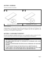
SECTION 1 - MATERIAL
This floor protection kit includes:
2X
1X
Panels with clips* (18″X 46 ¾″)
Middle panel* (18″ X 46 ¾″)
Table 1 : Box contents
*Insulated with ½″ of Micore 300. Micore 300 is rated with a 1.03 R factor at ½″ thickness. The
R factor of the floor protection must be equal or greater than the one required by the
manufacturer of the appliance being installed.
SECTION 2 - FLOOR AREA TO PROTECT
All solid fuel appliances should be placed on a non combustible surface to protect the floor
from hot embers that could fall from the appliance during loading and maintenance.
ATTENTION
• THE FLOOR PROTECTION MUST NOT BE CUT OR TRIMMED.
• THE FLOOR PROTECTION MUST BE INSTALLED IN ACCORDANCE WITH LOCAL
BUILDING CODE
• THE FLOOR PROTECTION MUST BE INSTALLED ON A CONTINUOUS, FLAT AND LEVEL
SURFACE.
• THE FLOOR PROTECTION MAY NOT BE INSTALLED ON A CARPETED SURFACE.
• ALWAYS REFER TO THE CERTIFICATION PLATE ON THE APPLIANCE FOR THE FLOOR
AREA TO PROTECT. USE THE FOLLOWING TABLE AS AN INDICATION ONLY.

Page 3
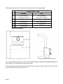
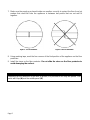
The floor protection must cover the area mentioned in the following table:
FLOOR PROTECTION
CANADA
USA
A
18" (457 mm)
From door opening
16" (406 mm)
From door opening
B
8" (203 mm)
N/A (Canada only)
C
8" (203 mm)*
N/A (Canada only)
D
N/A (USA only)
8" (203 mm)
E
8" (203 mm)
**
Table 2: Floor Protection
Figure 1: Top View - Floor Protection
Figure 2 : Side View - Floor Protection
*The floor protection at the back of the stove (C) is limited to the stove’s required clearance if
such clearance is smaller than 8 inches (203 mm).
**Only required under the horizontal section of the connector. Must exceed each side of the
connector by at least 2 inches (51 mm).

Page 4
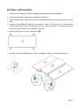
SECTION 3 - INSTALLATION
1. Determine the appliance position following manufacturer’s recommendations.
2. Determine necessary dimensions for the floor protection.
3. Using masking tape, mark the four corners of the final position of the floor protection on the
floor.
4. Align one panel (A), matching the rear marks of step 3. Note that one of these panels
contains two small holes on the thickness of one of the long sides. For aesthetic reasons,
place this panel so that it is as invisible as possible.
5. Remove the spacers on the middle panel (B).
Figure 3 : Spacers position
6. Insert the middle panel (B) and the other panel (A), as shown on the following figure.
Figure 4 : Floor Protection

Page 5
7. Make sure the panels are placed inside one another correctly to protect the floor from hot
embers that could fall from the appliance in between two panels that are not well fit
together.
Figure 5 : Correct installation
Figure 6 : Incorrect installation
8. Using masking tape, mark the four corners of the final position of the appliance on the floor
protection.
9. Install the stove on the floor protector. Do not slide the stove on the floor protector to
avoid damaging the surface.
NOTE
Depending on the dimension of the floor to protect, it is possible to use only two panels. One
panel with clips (A) and the middle panel (B).
-
 1
1
-
 2
2
-
 3
3
-
 4
4
-
 5
5


Drolet AUSTRAL III WOOD STOVE Assembly Instructions
- Type
- Assembly Instructions
- This manual is also suitable for
Ask a question and I''ll find the answer in the document
Finding information in a document is now easier with AI
Related papers
-
 Drolet CAPE TOWN 1800 CAST IRON WOOD STOVE Owner's manual
-
 Drolet ESCAPE 1400-I WOOD INSERT TRIO User manual
-
 Drolet ESCAPE 1500-I WOOD INSERT TRIO Owner's manual
-
 Drolet Escape 1800 Insert Owner's manual
-
Drolet DB03125 Owner's manual
-
-
Drolet ECO-55 PELLET STOVE Assembly Instructions


Other documents
-
 Century Heating CW2500 Owner's manual
-
BuckMaster 81 User manual
-
 Lennox Hearth CI2000HT User manual
-
Quadra-Fire 32198A User manual
-
Lennox Spectra CI2000HT User manual
-
 Ventis HE275CF Wood Fireplace VB00017 User manual
-
Century CW2500-I WOOD INSERT Owner's manual
-
Heatiator C40 User manual
-
-
Hearth and Home Technologies NorthStar-GT User manual


