
User´s Guide
VEXG (Gigabit Ethernet) / VEXU (USB 3.0)
Document Version: v1.5
Release: 25.10.2018
Document Number: 11165414

2

3
Table of Contents
1. General Information ................................................................................................. 6
2. General safety instructions ..................................................................................... 8
3. General Description ................................................................................................. 9
3.1 VEXG .....................................................................................................................11
3.2 VEXU .....................................................................................................................11
4. Camera Models ....................................................................................................... 12
4.1 VEXG .................................................................................................................... 12
4.2 VEXU .................................................................................................................... 13
5. Installation .............................................................................................................. 14
5.1 Environmental Requirements ................................................................................ 14
5.2 Heat Transmission ................................................................................................ 14
5.3 Lens mounting ...................................................................................................... 15
5.4 Filter replacement ................................................................................................. 16
5.5 Cleaning ................................................................................................................ 16
5.6 Transport / Storage ............................................................................................... 17
5.7 Mechanical Tests ................................................................................................... 18
6. Pin-Assignment / LED-Signaling .......................................................................... 19
6.1 VEXG .................................................................................................................... 19
6.1.1 Ethernet Interface ........................................................................................... 19
6.1.2 Power Supply and Digital-IOs ........................................................................ 20
6.1.3 Digital-IO......................................................................................................... 20
6.1.4 LED Signaling ................................................................................................. 20
6.2 VEXU .................................................................................................................... 21
6.2.1 USB 3.0 Interface ........................................................................................... 21
6.2.2 Digital-IOs ....................................................................................................... 21
6.2.3 Digital-IO......................................................................................................... 21
6.2.4 LED Signaling ................................................................................................. 22
7. ProductSpecications .......................................................................................... 23
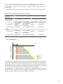
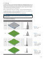
7.1 Sensor Specications ........................................................................................... 23
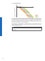
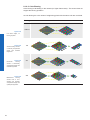
7.1.1 Spectral Sensitivity ......................................................................................... 23
7.1.2 Sensor Shutter Mode (only cameras with Rolling Shutter sensors) ............... 25
7.2 Field of View Position ............................................................................................ 27
7.2.1 VEXG.............................................................................................................. 27
7.2.2 VEXU .............................................................................................................. 27
7.3 Acquisition Modes and Timings ............................................................................. 28
7.3.1 Continuous Mode (Free Running Mode) ........................................................ 28
7.3.2 Single Frame Mode ........................................................................................ 29
7.3.3 Multi Frame Mode........................................................................................... 29
7.3.4 Acquisition Frame Rate (except cameras with Rolling Shutter sensors) ........ 29
7.3.5 Trigger Mode .................................................................................................. 30

4
7.4 Software ................................................................................................................ 35
7.4.1 Baumer GAPI ................................................................................................. 35
7.4.2 3
rd
Party Software ........................................................................................... 35
8. Camera Functionalities .......................................................................................... 36
8.1 Image Acquisition .................................................................................................. 36
8.1.1 Image Format ................................................................................................. 36
8.1.2 Pixel Format ................................................................................................... 37
8.1.3 Exposure Time................................................................................................ 40
8.1.4 Fixed Pattern Noise Correction (FPNC) ......................................................... 41
8.1.5 Region of Interest ........................................................................................... 42
8.1.6 Binning............................................................................................................ 43
8.1.7 Brightness Correction ..................................................................................... 45
8.2 Analog Controls ..................................................................................................... 46
8.2.1 Offset / Black Level ......................................................................................... 46
8.2.2 Gain ................................................................................................................ 47
8.3 Pixel Correction ..................................................................................................... 48
8.3.1 General information ........................................................................................ 48
8.3.2 Correction Algorithm ....................................................................................... 49
8.3.3 Add Defect Pixel to Defect pixel list ................................................................ 49
8.4 Process Interface .................................................................................................. 51
8.4.1 Digital-IOs ....................................................................................................... 51
8.4.2 IO Circuits VEXG ............................................................................................ 52
8.4.3 IO Circuits VEXU ............................................................................................ 52
8.4.4 Trigger ............................................................................................................ 53
8.4.5 Trigger Source ................................................................................................ 53
8.4.6 Debouncer ...................................................................................................... 54
8.4.7 ExposureActive (Flash Signal) ....................................................................... 55
8.4.8 Frame Counter ............................................................................................... 56
8.5 Device Reset ......................................................................................................... 56
8.6 User Sets .............................................................................................................. 56
8.6.1 VEXG.............................................................................................................. 56
8.6.2 VEXU .............................................................................................................. 57
8.7 Factory Settings .................................................................................................... 57
8.8 Timestamp ............................................................................................................ 57
8.9 Start-Stop-Behaviour ............................................................................................ 58
8.9.1 Start / Stop / Abort Acquisition (Camera) ........................................................ 58
8.9.2 Start / Stop Interface ...................................................................................... 58
9. VEXG – Interface Functionalities .......................................................................... 59
9.1 Device Information ................................................................................................ 59
9.2 Packet Size and Maximum Transmission Unit (MTU) ........................................... 59
9.3 Inter Packet Gap (IPG) ......................................................................................... 59
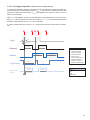
9.3.1 Example 1: Multi Camera Operation – Minimal IPG ....................................... 60
9.3.2 Example 2: Multi Camera Operation – Optimal IPG ....................................... 60
9.4 Multicast ................................................................................................................ 61
9.5 IP Conguration .................................................................................................... 62
9.5.1 Persistent IP ................................................................................................... 62
9.5.2 DHCP (Dynamic Host Conguration Protocol) ............................................... 62
9.5.3 LLA ................................................................................................................. 63
9.5.4 Force IP .......................................................................................................... 63

5
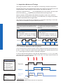
9.6 Packet Resend ...................................................................................................... 64
9.6.1 Normal Case................................................................................................... 64
9.6.2 Fault 1: Lost Packet within Data Stream ........................................................ 64
9.6.3 Fault 2: Lost Packet at the End of the Data Stream ....................................... 65
9.6.4 Termination Conditions ................................................................................... 65
10. VEXU – Interface Functionalities .......................................................................... 66
10.1 Device Information .............................................................................................. 66

6
1. General Information
Thanks for purchasing a camera of the Baumer family. This User´s Guide describes how
to connect, set up and use the camera.
Read this manual carefully and observe the notes and safety instructions!
Support
In the case of any questions please contact our Technical & Application Support Center.
Worlwide: Baumer Optronic GmbH
Badstrasse 30
DE-01454 Radeberg, Germany
Tel: +49 (0)3528 4386 845
Website: www.baumer.com
E-mail: support.cameras@baumer.com
Target group for this User´s Guide
This User's Guide is aimed at experienced users, which want to integrate camera(s) into
a vision system.
Intended Use
The camera is used to capture images that can be transferred over a GigE interface
(VCXG) or a USB 3.0 interface (VCXU) to a PC.
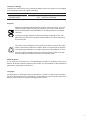
Classicationofthesafetyinstructions
In the User´s Guide, the safety instructions are classied as follows:
Notice
Gives helpful notes on operation or other general recommendations.
Caution
Pictogram
Indicates a possibly dangerous situation. If the situation is not avoided, slight
or minor injury could result or the device may be damaged.

7
Transport / Storage
Transport the camera only in the original packaging. When the camera is not installed,
then storage the camera in original packaging.
Storage Environment
Storage temperature -10 °C ... +70 °C ( +14 °F ... +158 °F)
Storage Humidy 10% ... 90% non condensing
Disposal
Dispose of outdated products with electrical or electronic circuits, not in the
normal domestic waste, but rather according to your national law and the
directives 2002/96/EC and 2006/66/EC for recycling within the competent
collectors.
Through the proper disposal of obsolete equipment will help to save valu-
able resources and prevent possible adverse effects on human health and
the environment.
The return of the packaging to the material cycle helps conserve raw mate-
rials an reduces the production of waste. When no longer required, dispose
of the packaging materials in accordance with the local regulations in force.
Keep the original packaging during the warranty period in order to be able
to pack the device properly in the event of a warranty claim.
Warranty Notes
If it is obvious that the device is / was dismantled, reworked or repaired by other than
Baumer technicians, Baumer Optronic will not take any responsibility for the subsequent
performance and quality of the device!
Copyright
Any duplication or reprinting of this documentation, in whole or in part, and the reproduc-
tion of the illustrations even in modied form is permitted only with the written approval of
Baumer. This document is subject to change without notice.

8
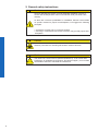
2. General safety instructions
Caution
Heat can damage the camera. Provide adequate dissipation of heat, to
ensure that the temperature does not exceed the value (see Heat Trans-
mission).
As there are numerous possibilities for installation, Baumer recommends
no specic method for proper heat dissipation, but suggest the following
principles:
▪ operate the cameras only in mounted condition
▪ mounting in combination with forced convection may provide proper heat
dissipation
Caution
Observe precautions for handling electrostatic sensitive devices!
Caution
Class A
The camera is a class A device (DIN EN 55022:2011). It can cause radio
interference in residential environments. Should this happen, you must take
reasonable measures to eliminate the interference.

9
3. General Description
All Baumer cameras of these families are characterized by:
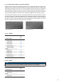
Best image quality ▪ Low noise and structure-free image information
▪ High quality mode with minimum noise
Flexible image acquisition ▪ Industrially-compliant process interface with parameter
setting capability
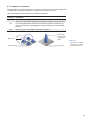
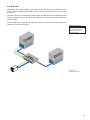
Fast image transfer VEXG ▪ Reliable transmission up to 1000 Mbit/sec
according to IEEE802.3
▪ Cable length up to 100 m
▪ Baumer driver for high data volume with low
CPU load
▪ High-speed multi-camera operation
▪ GenICam™ and GigE Vision
®
compliant
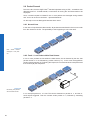
VEXU ▪ Reliable transmission at 5000 Mbit/sec
according to USB 3.0 (v1.0.1) standard
▪ GenICam™ and USB3 Vision
TM
compliant
Perfect integration ▪ Flexible generic programming interface (Baumer GAPI)
for all Baumer cameras
▪ Powerful Software Development Kit (SDK) with sample
codes and help les for simple integration
▪ Baumer viewer for all camera functions
▪ GenICam™ compliant XML le to describe the camera
functions
▪ Supplied with installation program with automatic
camera recognition for simple commissioning
Compact design ▪ Light weight
▪ exible assembly
Reliable operation ▪ State-of-the-art camera electronics and precision
mechanics
▪ Low power consumption and minimal heat generation
Supported standards VEXG ▪ v2.0 (v1.2 backward compatible)
▪ GenICam SFNC 2.1
VEXU ▪ USB3 Vision
TM
1.0.1
▪ GenICam GenCP 1.1
▪ GenICam SFNC 2.1
Conformity CE We declare, under our sole respon-
sibility, that the previously described
Baumer cameras conform with the
directives of the CE.
RoHS All VCX cameras comply with the
recommendation of the European
Union concerning RoHS rules.
KC Several of the described Baumer
VEX cameras conform with the di-
rectives of the Korean Conformity.
(see table on next page)

10
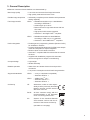
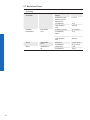
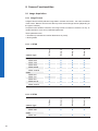
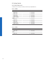
Korean Conformity (Registration of Broadcasting and Communication Equipments)
VEXG
Product Article No. Registration No. Date of Registration
Monochrome
VEXG-52M.R 11185978 R-REI-BkR-VEXG-52MR 2018-07-10
VEXG-100M.R 11185979 R-REI-BkR-VEXG-100MR 2018-07-10
Color
VEXG-52C.R 11185977 R-REI-BkR-VEXG-52MR 2018-07-10
VEXG-100C.R 11185990 R-REI-BkR-VEXG-100MR 2018-07-10

11
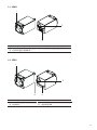
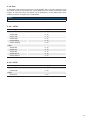
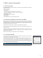
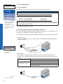
3.1 VEXG
2
3
1
No. Description No. Description
1 Lens mount (CS-Mount) 3 Ethernet Port / Signaling LED´s
2 Power supply / Digital-IO
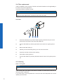
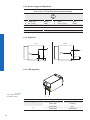
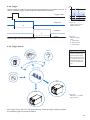
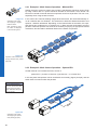
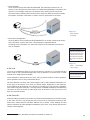
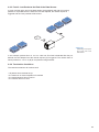
3.2 VEXU
2
43
1
No. Description No. Description
1 Lens mount (CS-Mount) 3 USB 3.0 port
2 Digital-IO 4 Signaling-LED

12
4. Camera Models
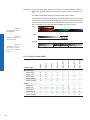
4.1 VEXG
Camera Type
Sensor
Size
Resolution
Full
Frames
[max. fps]
Monochrome
VEXG-02M 1/4" 640 × 480 217
VEXG-13M 1/2" 1280 × 1024 61
VEXG-25M 2/3" 1920 × 1200 41
VEXG-52M.R 1/2.5" 2592 × 1944 14
VEXG-100M.R 1/2.3" 3856 × 2764 7
Color
VEXG-02C 1/4" 640 × 480 217
VEXG-13C 1/2" 1280 × 1024 61
VEXG-25C 2/3" 1920 × 1200 41
VEXG-52C.R 1/2.5" 2592 × 1944 14
VEXG-100C.R 1/2.3" 3856 × 2764 7
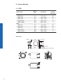
Dimensions
29
29
20
20
4,45
7,2
8,7
20
3
28,7
20
22
40
CS-mount
1,55 ±0,3548,98,9
3
8 x M3 x 4
2 x M3 x 4
ø
1,3±0,35 (VEXG-52 / VEXG-100)

13
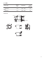
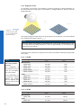
4.2 VEXU
Camera Type
Sensor
Size
Resolution
Full
Frames
[max. fps]
Monochrome
VEXU-24M 1/1.2" 1920 × 1200 38
Color
VEXU-24C 1/1.2" 1920 × 1200 38
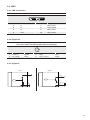
Dimensions
29
29
20
18
6,15
8,2
6
20
3
28,7
20
22
30
CS-mount
1,55 ±0,3537,88,4
3
8 x M3 x 4
2 x M3 x 4
ø

14
5. Installation
5.1 Environmental Requirements
Temperature
Storage temperature -10 °C ... +70 °C ( +14 °F ... +158 °F)
Operating temperature + 5 °C (+14 °F) ... see „Heat Transmission“
Humidity
Storage and Operating Humidity 10% ... 90%
Non-condensing
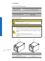
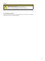
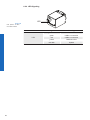
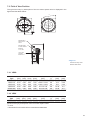
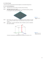
5.2 Heat Transmission
Caution
Device heats up during operation.
Skin irritation possible.
Do not touch the camera during operation.
Caution
Heat can damage the camera. Provide adequate dissipation of heat, to en-
sure that the temperatures does not exceed the values in the table below.
As there are num erous possibilities for installation, Baumer recommends
no specic method for proper heat dissipation, but suggest the following
principles:
▪ operate the cameras only in mounted condition
▪ mounting in combination with forced convection may provide proper heat
dissipation
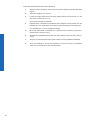
T
T
Measure Point (T) Maximal Temperature
VEXG VEXU
65 °C (149 °F)
VEXG-100 / VEXG-52: 60 °C (140 °F)
65 °C (149 °F)
Figure1►
Temperature measuring
point

15
5.3 Lens mounting
Notice
Avoid contamination of the sensor and the lens by dust and airborne particles when
mounting the lens to the device!
Therefore the following points are very important:
▪ Install the camera in an environment that is as dust free as possible!
▪ Keep the dust cover (bag) on camera as long as possible!
▪ Hold the camera downwards with unprotected sensor.
▪ Avoid contact with any optical surface of the camera!

16
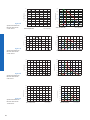
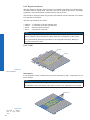
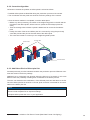
5.4 Filter replacement
A lter is installed in color cameras. This lter can lead to limitations in the applicability of
the sensor for specic applications.
Proceed as follows to replace the lter.
Notice
Avoid contamination of the lter, sensor and the lens by dust and airborne particles!
Perform the lter replacement in a dust-free room with clean tools!
Procedure
1
2
3
4
1. Insert the assembly tool (1) into the sensor opening. Place the two pins at the
front end into the locator holes of the lter holder (2).
2. Turn the lter holder (2) until the guide tabs can be seen in the guide grooves
(4).
3. Remove the lter holder (2).
4. Carefully remove the existing lter (3). Do not touch the sensor!
5. Insert the new lter into the sensor opening.
6. Put the lter holder (2) back in.
7. Turn the lter holder (2) until the guide tabs cannot be seen in the guide grooves
(4).
5.5 Cleaning
Filter / Cover glass
Notice
The sensor is mounted dust-proof. Remove of the cover glass for cleaning is not neces-
sary.
Avoid cleaning the cover glass of the sensor if possible. To prevent dust, follow the in-
structions under "Install lens".
If you must clean it, use compressed air or a soft, lint free cloth dampened with a small
quantity of pure alcohol.

17
Housing
Caution!
volatile
solvents
Volatile solvents for cleaning.
Volatile solvents damage the surface of the camera.
Never use volatile solvents (benzine, thinner) for cleaning!
To clean the surface of the camera housing, use a soft, dry cloth. To remove persistent
stains, use a soft cloth dampened with a small quantity of neutral detergent, then wipe dry.
5.6 Transport / Storage
Transport the camera only in the original packaging. When the camera is not installed,
then storage the camera in original packaging.

18
5.7 Mechanical Tests
Environmen-
tal Testing
Standard Parameter
Vibration,
sinusodial
IEC 60068-2-6 Frequency
Range
10-2000 Hz
Amplitude under-
neath crossover
frequencies
1.5 mm
Acceleration 10 g
Test duration /
Axis
150 min
Vibration,
broad band
IEC 60068-
2-64
Frequency range 20-1000 Hz
Acceleration
RMS
10 g
Test duration /
Axis
300 min
Shock IEC 60068-
2-27
Puls time 11 ms / 6 ms
Acceleration 50 g / 100 g
Bump IEC60068-2-
29
Pulse Time 2 ms
Acceleration 100 g

19
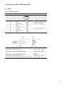
6. Pin-Assignment / LED-Signaling
6.1 VEXG
6.1.1 Ethernet Interface
8P8C Modular Jack (RJ45) with LEDs
1
8
1 green/white MX1+ (negative / positive V
port
)
2 green MX1- (negative / positive V
port
)
3 orange/white MX2+ (positive / negative V
port
)
4 blue MX3+
5 blue/white MX3-
6 orange MX2- (positive / negative V
port
)
7 brown/white MX4+
8 brown MX4-
Dimension - Free Connector (cable) Type090
From overmold to plug stop (A1) 9.0mm (-0.50, +0.00)
From overmold to tip of thumbscrews (B1) 4.25mm (-1.00, +0.25)
Dimension – Fixed Connector (camera) Type090
From contact point to plug stop (A2) 9.0mm (-0.00, +1.00)
From contact point to bottom of thumbscrew thread (B2) 4.5mm (-0.00, +1)

20
6.1.2 Power Supply and Digital-IOs
Power Supply / Digital-IOs (on camera side)
wire colors on connecting cable (ordered separately)
1
2
4
3
1 Power VCC
brown
3 GND
blue
2 IN1 (Line0)
white
4 OUT1 (Line1)
black
Power Supply
Power Supply V
CC
: 12 … 24 VDC ± 20%
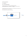
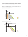
6.1.3 Digital-IO
Input
Output
Pin 2
(IN1)
FPGA
FPGA
Pin 3
(GND)
Pin 1
(Power VCC)
Pin 4
(OUT)
R
L
(+12 ... 24 VDC ± 20 %)
Pin 3
(GND)
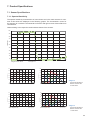
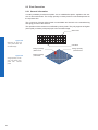
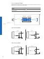
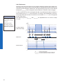
6.1.4 LED Signaling
21
LED Signal Meaning
1
green static link active
green ash receiving
2
yellow static error
yellow ash transmitting
Figure2►
LED positions on Bau-
mer VEXG cameras.
Page is loading ...
Page is loading ...
Page is loading ...
Page is loading ...
Page is loading ...
Page is loading ...
Page is loading ...
Page is loading ...
Page is loading ...
Page is loading ...
Page is loading ...
Page is loading ...
Page is loading ...
Page is loading ...
Page is loading ...
Page is loading ...
Page is loading ...
Page is loading ...
Page is loading ...
Page is loading ...
Page is loading ...
Page is loading ...
Page is loading ...
Page is loading ...
Page is loading ...
Page is loading ...
Page is loading ...
Page is loading ...
Page is loading ...
Page is loading ...
Page is loading ...
Page is loading ...
Page is loading ...
Page is loading ...
Page is loading ...
Page is loading ...
Page is loading ...
Page is loading ...
Page is loading ...
Page is loading ...
Page is loading ...
Page is loading ...
Page is loading ...
Page is loading ...
Page is loading ...
Page is loading ...
Page is loading ...
Page is loading ...
-
 1
1
-
 2
2
-
 3
3
-
 4
4
-
 5
5
-
 6
6
-
 7
7
-
 8
8
-
 9
9
-
 10
10
-
 11
11
-
 12
12
-
 13
13
-
 14
14
-
 15
15
-
 16
16
-
 17
17
-
 18
18
-
 19
19
-
 20
20
-
 21
21
-
 22
22
-
 23
23
-
 24
24
-
 25
25
-
 26
26
-
 27
27
-
 28
28
-
 29
29
-
 30
30
-
 31
31
-
 32
32
-
 33
33
-
 34
34
-
 35
35
-
 36
36
-
 37
37
-
 38
38
-
 39
39
-
 40
40
-
 41
41
-
 42
42
-
 43
43
-
 44
44
-
 45
45
-
 46
46
-
 47
47
-
 48
48
-
 49
49
-
 50
50
-
 51
51
-
 52
52
-
 53
53
-
 54
54
-
 55
55
-
 56
56
-
 57
57
-
 58
58
-
 59
59
-
 60
60
-
 61
61
-
 62
62
-
 63
63
-
 64
64
-
 65
65
-
 66
66
-
 67
67
-
 68
68


Ask a question and I''ll find the answer in the document
Finding information in a document is now easier with AI
Related papers
-
Baumer VEXG-52M.R Quick start guide
-
Baumer VEXU-24C Quick start guide
-
-
Baumer VLG-22C.I User guide
-
Baumer HXC40c Operating instructions
-
Baumer VCXG-13C Quick start guide
-
-
Baumer VCXU-31C Quick start guide
-
Baumer VLG-20M User guide
-
Other documents
-
PYLE Audio UPDBC10 User manual
-
 ISG Allegro LW-AL-CMV12000C-USB3 COLOR Technical Manual
-
JAI SW-2000M-CL-65 User manual
-
Xerox 96 IPS User manual
-
 Mikrotron EOSENS GE CAMERA User manual
-
 Acksys WLg-LINK-OEM Quick start guide
-
Hirschmann OWL-IPG-AMERICAS User manual
-
 Photon Focus MV1-D2080(IE) Series User manual
-
 Hexbug VEX IQ User manual
-
Omron Factory Drive Recorder User guide


