Page is loading ...

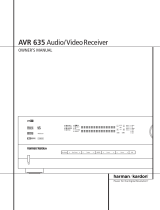
AVR 255/AVR 355 Audio/Video Receiver
OWNER’S MANUAL
Composit
AVR
Info
R
esolution Audio Effects
Video Modes
S
urround Modes
Back/Exit
S
ource List
AB
L
K
OK
ENGLISH

Table of Contents
Typographical Conventions
In order to help you use this manual with the remote control, front-panel controls and rear-panel
connections, certain conventions have been used.
EXAMPLE – (bold type) indicates a specific remote control or front-panel button, or rear-panel
connection jack
EXAMPLE – (OCR type) indicates a message that is visible on the front-panel information display
1 – (number in a square) indicates a specific front-panel control
– (number in a circle) indicates a rear-panel connection
A – (letter in a square) indicates a button or indicator on the remote
A – (letter in an oval) indicates a button on the Zone 2 remote
The appearance of the text or cursor for your receiver’s on-screen menus may vary slightly from the
illustrations in this manual. Whether the text appears in all uppercase or upper- and lowercase
characters, performance and operation remain the same.
2 TABLE OF CONTENTS
3 I
ntroduction
4 S
afety Information
5 Unpacking
6 Front Panel Controls
8 Rear Panel Connections
1
1
Main Remote Control Functions
13 Zone 2 Remote Control Functions
1
5
Installation and Connections
15 Audio Equipment Connections
15 HDMI Input Connections
15 HDMI Output Connections
16 Analog and Digital Input Connections
17 Video Equipment Connections
18 System and Power Connections
18 Main Room Remote Control Extension
18 Zone 2 IR Link
18 Multiroom Audio Connection
18 A
-BUS Installation Connections
19 Speaker Selection
19 S
peaker Placement
20 System Configuration
20 First Turn On
20 Using the On-Screen Display
20 System Setup
20 Source Selection
21 Audio and Video Input Selection
21 Set Up Sources
21 Audio Effects
21 Video Mode
21 Surround Mode
21 Audio Format From Source
21 Video Input From Source
21 Audio Input From Source
21 Resolution To Display
22 Resolution From Source
22 Adjust Lip Sync
22 Change Source Name
22 Zone 2 Audio
22 Speaker Setup, EzSet/EQ
22 Speaker Setup, Manual
28 Operation
28 Surround Mode Chart
30 Basic Operation
30 Mute Function
30 Audio Effects
30 Video Modes
30 Source Selection
30 Video Input Selection
31 Video Troubleshooting Tips
31 Multichannel Disc Players with/without
HDMI
31 6/8-Channel Direct Input
31 Controls and Use of Headphones
31 Surround Mode Selection
32 Digital Audio Signals
33 Surround modes
34 Tape Recording
34 The Bridge
35 Multiroom Operation
35 Multiroom Setup
35 Surround Amplifier Channel Assignment
37 Video Adjustments
37 Video Modes
38 Audio Adjustments
38 Audio Effects
38 Advanced Features
38 System Settings
38 Front Panel Dimmer
38 Volume Units
38 Volume Default and Level
38 Unit of Measure
38 iPod Charging
38 On-Screen Language
38 HDMI Audio to TV
38 Resolution to Display
39 Menu Appearance
39 OSD Transparency
39 Volume Status Messages
39 Menus
39 S
etup and Slide-In Menus
39 S
creen Saver
39 D
efault Surround Mode
40 T
uner Operation
40 To Select the Built-In Tuner
40 RDS Functions
42 Programming the Remote
42 Programming with Codes
42 Direct Code Entry
42 Auto Search Method
42 Code Readout
43 Learning Codes from a Remote
43 Erasing Learned Codes
44 Activity Programming (Macros)
44 Programmed Device Functions
45 Notes on Using the AVR Remote With
Other Devices
45 Punch-Through Programming
45 Resetting the Remote Memory
46 AVR 355 Remote Function List
48 AVR 255 Remote Function List
50 Troubleshooting Guide
50 Processor Reset
51 Technical Specifications
52 Appendix - Settings Worksheet
Declaration of Conformity
We, Harman Consumer Group, Inc.
2, route de Tours
72500 Château-du-Loir,
FRANCE
declare in own responsibility, that the product described in this
owner’s manual is in compliance with technical standards:
EN55013(2001) & + A2(2006)
EN55020(2002) & + A2(2005)
EN60065:2002
EN61000-3-2(2000)+A2(2005)
EN61000-3-3 (1995)+A1(2001)+A2(2005)
EN61000-4-2(1995) & + A1(1998) & + A2(2001)
EN61000-4-3(2002) & + A1(2002)
EN61000-4-4(2004)
Jurjen Amsterdam
Harman Consumer Group, Inc.
03/08

Introduction
Thank you for choosing Harman Kardon!
With the purchase of a Harman Kardon AVR 255/
AVR 355 you are about to begin many years of
listening enjoyment. Designed to provide all the
excitement and detail of movie soundtracks and
every nuance of musical selections, the AVR 255/
AVR 355 are truly multichannel receivers for the
n
ew millennium. In addition to the traditional 5.1
digital decoding modes such as Dolby Digital and
DTS, they offer the latest advancements in sur-
round technology such as Dolby
®
True HD and
DTS
®
-HD Master Audio™ and the latest 7.1
channel versions of Harman's own Logic 7
technology.
The AVR 255/AVR 355 have been engineered so
that it is easy to take advantage of all the
power of their digital technology. Full-color,
high-definition, multi-language on-screen
menus, fully color coded connection jacks and
terminals make installation fast and simple.
However, to obtain the maximum enjoyment
from your new receiver, we urge you to read this
manual. A few minutes spent learning the func-
tions of the various controls will enable you to
take advantage of all the power the AVR is able
to deliver.
If you have any questions about this product, its
installation or its operation, please contact your
retailer or custom installer. They are your best
local sources of information.
Description and Features
The AVR serves as the hub of your home enter-
tainment system, providing a wide range of lis-
tening possibilities for almost any audio or video
program source, whether it is the broadcast of a
movie or sporting event in HDTV or a vintage
mono or stereo recording. When playing digital
audio sources from either the conventional opti-
cal and coaxial inputs, or through the HDMI 1.3a
compliant connections, the AVR decodes Dolby
True HD, Dolby Digital Plus, DTS-HD Master
Audio and DTS-HD data streams. Two-channel
stereo and matrix surround sources benefit from
all current Dolby Pro Logic IIx modes and DTS
Neo:6. The latest version of our proprietary Logic
7
®
process is on-board to create a wider, more
enveloping sound field and more defined sur-
round channel positioning, regardless of the type
of source material.
Dolby Virtual Speaker is available to create
enveloping sound fields from front left and right
speakers, and the latest Dolby Headphone
circuitry creates an amazing sense of openness
with headphones.
The AVR takes the “video” part of its name seri-
ously. Along with three HDMI inputs and three
100MHz analog component video inputs (two
on the AVR 255), the AVR’s video processing
allows you to scale the output signal to 1080p
loop-through to match the requirements of your
specific video display. Thanks to award winning
F
aroudja
®
D
CDi Cinema™ technology, your
video sources never looked better. Tying audio
and video together, the AVR provides A/V sync
delay so that the lip sync errors – commonly
seen when digital video processing is used in a
source, program or video display – are
eliminated.
An important addition to the AVR’s impressive
list of features is EzSet/EQ
™
, which automates
the configuration process to make it quicker, eas-
ier and more precise. Using the special micro-
phone supplied with the unit, EzSet/EQ takes the
guesswork out of entering speaker “size” and
crossover information, delay times for all chan-
nels and output levels. In addition to the config-
uration settings, EzSet/EQ also includes room
equalization so that the signals sent to each
speaker are tailored to provide accurate sonic
quality with your specific combination of speaker
type, room size and other factors that influence
room acoustics. With EzSet/EQ, your system is
custom-configured in a few minutes with accu-
racy that previously required expensive and
hard-to-use test equipment.
In tandem with EzSet/EQ, the AVR includes a full
set of manual configuration settings for those
who wish to custom-trim their system even fur-
ther. A Quadruple Crossover bass management
system makes it possible to enter different
crossover settings for each speaker group.
A Stereo-Direct mode bypasses the digital
processor to preserve all of the subtleties of older
analog, two-channel materials, while bass
management, available in the surround and
Stereo-Digital modes, improves your ability to
tailor the sound to suit your room acoustics or
taste.
For the ultimate in flexibility, the AVR’s feature
connections for four video devices, all with both
composite and S-Video inputs. Two additional
audio inputs are available, and a total of six
digital inputs and two outputs make the AVR
capable of handling all the latest digital audio
sources. For compatibility with the latest HDTV
video sources and progressive scan DVD players,
the AVR also features wide-bandwidth, low-
crosstalk component video switching.
Coax and optical digital outputs are available for
direct connection to digital recorders. A video
recording output and a color-coded eight-chan-
nel input make the AVR virtually future-proof,
with everything needed to accommodate tomor-
row’s new formats right on board.
With one simple connection between the
AVR 355 and the optional Harman Kardon
, you are able to listen to materials
stored on your compatible Apple
®
iPod
®
**.
Your AVR’s system remote control has been
preprogrammed with control codes that enable
you to select tracks for playback and navigate
m
any of your iPod’s functions, even from across
the room. The Bridge™ will even let you charge
your iPod.
The AVR 355’s flexibility and power extend
beyond your main home theater or listening
room. The AVR includes a sophisticated multi-
zone control system that allows you to select
one source for use in the main room and a
different one (Audio only) in a second room.
Complete control over volume is possible with a
separate infrared control link. To make it easy to
operate the AVR from a remote room, a separate
“Zone II” remote is included.
Additional multiroom options include the option
to assign two of the AVR’s output channels to the
multiroom system and the ability to link the AVR
to innovative A-BUS
®
keypads for multiroom oper-
ation without the need for external amplifiers.
The AVR’s powerful amplifier uses traditional
Harman Kardon high-current design technolo-
gies to meet the wide dynamic range of any pro-
gram selection.
Harman Kardon invented the high-fidelity
receiver more then fifty years ago. With state-of-
the-art circuitry and time-honored circuit
designs, the AVR 255 and AVR 355 are the
perfect combination of the latest in digital audio
technology, a quiet yet powerful analog
amplifier in an elegant, easy-to-use package.
**Compatible with all iPod models equipped with a dock connector, including third-generation “Click Wheel” models and newer. Not compatible with iPod
shuffle models. Although iPod photo models are compatible, images stored on the iPod can only be viewed using the controls on the iPod, not with the
AVR remote.
ENGLISH
INTRODUCTION 3

Safety Information
I Dolby True HD, Dolby Digital Plus, Dolby
Digital EX and Dolby Pro Logic* II and
IIx Decoding, and the full suite of DTS
®
modes, including DTS-HD Master Audio,
DTS-HD and DTS-ES
®
6.1 Discrete &
Matrix and Neo:6
®
I
Seven channels of high-current amplifi-
cation with two channels assignable to
either surround back or multiroom
a
pplications
I Harman Kardon’s exclusive Logic 7
®
processing, along with a choice of
Dolby Virtual Speaker processing for
use when only two speakers are
available
I Dolby Headphone to create spacious,
open sound fields when using head-
phones
I Harman Kardon’s advanced EzSet/EQ
™
automatically configures speaker set-
tings and sets room equalization for
quick, easy and accurate system setup
I HDMI with audio/video processing,
upscaling to 720p/1080p and repeater
for increased cable length without sig-
nal degradation
I Three HDMI
™
1.3a and three (two on
AVR 255) assignable high-bandwidth
analog component inputs for compati-
bility with the latest high-definition
video sources
I Front panel analog A/V inputs
I Front panel digital inputs for easy con-
nection to portable digital devices and
the latest video game consoles
I Connects to Harman Kardon’s
(optional) for charging, playback and
control of a compatible Apple
®
iPod
®
device (AVR 355 only)
I Input titling for all input sources
(except tuner)
I Multiple digital inputs and outputs
I Full-color, high-definition, multi-lan-
guage On-screen menu and display sys-
tem
I A/V Sync delay adjustable for each
input delivers perfect lip sync with
digital programs or video displays
I 6-Channel/8-Channel Direct Input for
Use with Future Audio Formats
I Extensive bass management options,
including four separate crossover
groupings
I Extensive multiroom options, including
a standard Zone II remote, assignable
amplifier channels and A-BUS Ready
®
capability for listening to a separate
source in a remote zone (AVR 355 only)
I Main Remote with Internal Codes
I
mportant Safety Instructions
Please read the following precau-
tions before use:
1. Read these instructions.
2. Keep these instructions.
3
. Heed all warnings.
4. Follow all instructions.
5. Do not use this apparatus near water.
6. Clean only with a dry cloth.
7. Do not block any ventilation openings. Install
in accordance with the manufacturer’s
instructions.
8. Do not install near any heat sources such as
radiators, heat registers, stoves or other
apparatus (including amplifiers) that produce
heat.
9. Do not defeat the safety purpose of the
polarized or grounding-type plug. A polarized
plug has two blades with one wider than the
other. A grounding-type plug has two blades
and a third grounding prong. The wide blade
or the third prong is provided for your safety.
If the provided plug does not fit into your
outlet, consult an electrician for replacement
of the obsolete outlet.
10.Protect the power cord from being walked on
or pinched, particularly at plugs, convenience
receptacles and the point where they exit
from the apparatus.
11.Only use attachments/accessories specified
by the manufacturer.
12.Use only with the cart, stand, tripod, bracket
or table specified by the manufacturer or sold
with the apparatus. When a cart is
used, use caution when moving the
cart/apparatus combination to
avoid injury from tip-over.
13.Unplug this apparatus during lightning
storms or when unused for long periods of
time.
14.Refer all servicing to qualified service
personnel. Servicing is required when the
apparatus has been damaged in any way,
such as power supply cord or plug is
damaged, liquid has been spilled or objects
have fallen into the apparatus, the apparatus
has been exposed to rain or moisture, does
not operate normally, or has been dropped.
15.Do not expose this apparatus to dripping or
splashing and ensure that no objects filled
with liquids, such as vases, are placed on the
apparatus.
16.To completely disconnect this apparatus from
the AC Mains, disconnect the power supply
cord plug from the AC receptacle.
17.The mains plug of the power supply cord
shall remain readily operable.
18.Do not expose batteries to excessive heat
such assunshine, fire or the like.
4 SAFETY INFORMATION

Safety Information
The lightning flash with arrowhead
symbol, within an equilateral triangle,
is intended to alert the user to the
presence of uninsulated “dangerous voltage”
within the product’s enclosure that may be of
sufficient magnitude to constitute a risk of
electric shock to persons.
The exclamation point within an
equilateral triangle is intended to alert
the user to the presence of important
operating and maintenance (servicing)
i
nstructions in the literature accompanying the
product.
WARNING:To reduce the risk of fire or electric
shock, do not expose this apparatus to rain or
moisture.
Instructions for users on removal
and disposal of used batteries.
Specification of included battery
types.
These symbols shown on the product, the packag-
ing or in the manual or separate information sheet
mean that the product itself, as well as the batter-
ies included or built into the product, should never
be thrown away with general household waste.
Take them to applicable collection points, where
proper treatment, recycling and recovery takes
place, in accordance with national or local legisla-
tion, or European Directives 2002/96/EC and
2006/66/EC.
Correct handling of the product and batteries to
be disposed helps save resources and prevents
possible negative effects on the environment or
human health.
The batteries included with your equipment may
be Alkaline, Carbon Zinc/Manganese or Lithium
(button cells) type.All types should be disposed of
according to the above instructions.
To remove the batteries from your equipment or
remote control, reverse the procedure described
for inserting batteries in the Owners Manual.
For products with a built-in battery that lasts for
the lifetime of the product, removal may not be
possible for the user. In this case, recycling or
recovery centers handle the dismantling of the
product and the removal of the battery. If, for any
reason, it becomes necessary to replace such a
battery, this procedure must be performed by
authorized service centers.
Pb
ENGLISH
SAFETY INFORMATION 5
Installation Location
I To assure proper operation and to avoid the
potential for safety hazards, place the unit on
a firm and level surface. When placing the
unit on a shelf, be certain that the shelf and
any mounting hardware can support the
weight of the product.
I Make certain that proper space is provided
both above and below the unit for ventilation.
I
f this product will be installed in a cabinet or
other enclosed area, make certain that there
is sufficient air movement within the cabinet.
Under some circumstances a fan may be
required.
I Do not place the unit directly on a carpeted
surface.
I Avoid installation in extremely hot or cold
locations, or an area that is exposed to direct
sunlight or heating equipment.
I Avoid moist or humid locations.
I Do not obstruct the ventilation slots on the
top of the unit, or place objects directly over
them.
I Due to the weight of the AVR and the heat
generated by the amplifiers, there is the remote
possibility that the rubber padding on the bot-
tom of the unit’s feet may leave marks on cer-
tain wood or veneer materials. Use caution
when placing the unit on soft woods or other
materials that may be damaged by heat or
heavy objects. Some surface finishes may be
particularly sensitive to absorbing such marks
due to a variety of factors beyond
Harman Kardon's control, including the nature
of the finish, cleaning materials used, and
normal heat and vibration caused by the use of
the product, or other factors. We recommend
that caution be exercised in choosing an
installation location for the component and in
normal maintenance practices, as your
warranty will not cover this type of damage to
furniture.
Cleaning
When the unit gets dirty, wipe it with a clean,
soft, dry cloth. If necessary, wipe it with a soft
cloth dampened with mild soapy water, then a
fresh cloth with clean water.
Wipe dry immediately with a dry cloth. NEVER
use benzene, aerosol cleaners, thinner, alcohol or
a
ny other volatile cleaning agent. Do not use
abrasive cleaners, as they may damage the finish
of metal parts. Avoid spraying insecticide near
the unit.
M
oving the Unit
Before moving the unit, be certain to disconnect
any interconnection cords with other compo-
nents, and make certain that you disconnect the
unit from the AC outlet.
Unpacking
The carton and shipping materials used to pro-
tect your new receiver during shipment were
specially designed to cushion it from shock and
vibration. We suggest that you save the carton
and packing materials for use in shipping if you
move, or should the unit ever need repair.
To minimize the size of the carton in storage,
you may wish to flatten it. This is done by care-
fully slitting the tape seams on the bottom and
collapsing the carton. Other cardboard inserts
may be stored in the same manner. Packing
materials that cannot be collapsed should be
saved along with the carton in a plastic bag.
If you do not wish to save the packaging
materials, please note that the carton and other
sections of the shipping protection are recycla-
ble. Please respect the environment and discard
those materials at a local recycling center.
It is important that you remove the protective plas-
tic film from the front-panel lens. Leaving the film
in place will affect the performance of your remote
control.

Front Panel Controls
1
2
3
4
5
6
7
8
9
)
!
@
#
$
%
^
&
*
(
Ó
Volume Control
System Power Control
Power Indicator
Headphone Jack
Menu Navigation Buttons
OK Button
AVR Button
Info Button
Resolution Button
Audio Effects Button
Video Modes Button
Source List Button
Main Information Display
Speaker/Channel Input Indicator
Surround Mode Button
Back/Exit Button
Digital Optical Front Input
Digital Coax Front Input
Video Front Input Jacks
Remote Sensor Window
Composite Analog
AVR
I
nfo
R
esolution Audio Effects
V
ideo Modes
S
urround Modes
B
ack/Exit
S
ource List
A
B
L
K
O
K
J
CD 0
21 6 7 8 9A
E
4
5B
I
G
H3
F
4
6 FRONT PANEL CONTROLS

1
Volume Control: Turn this knob clockwise
to increase the volume, counterclockwise to
decrease the volume. If the AVR is muted,
adjusting volume control will automatically
release the unit from the silenced condition.
2
System Power Control: When the Main
Power Switch on the rear panel is “ON,” press
this button to turn on the AVR; press it again to
turn the unit off (to Standby). Note that the
Power Indicator
3
will turn white when the
unit is on.
3
Power Indicator: This LED will be illuminated
in amber when the unit is in the Standby mode
to signal that the unit is ready to be turned on.
When the unit is in operation, the indicator will
turn white.
4
Headphone Jack: This jack may be used to
listen to the AVR’s output through a pair of head-
phones. Be certain that the headphones have a
standard 6,3 mm stereo phone plug. Note that
the speakers will automatically be turned off
when the headphones are connected.
When configuring your system using EzSet/EQ,
the calibration microphone should be plugged
into this jack using the supplied adaptor that
converts the small mini-plug at the end of the
microphone’s cord to a 6,3 mm plug.
5
Navigation: These buttons are used to navi-
gate the AVR’s menus and to operate the tuner.
6
OK Button: Press this button to select the
currently highlighted item.
7
AVR Settings Button: Press this button to
access the AVR’s main menu.
8
Info Settings Button: Press this button to
directly access the AVR’s Setup Source submenu,
which contains the settings for the current
source.
9
Resolution: Pressing this Button once and
then using the Up/Down Navigation Buttons
5
changes the AVR’s video output resolution to
these settings: 576i, 576p, 720p, 1080i or
1080p. The AVR is set to default to 576i when
first switched on, or if you reset it later. This reso-
lution has been chosen to ensure that the On
Screen Display information is visible on your TV
even with analog S-Video or Composite (CVBS)
signals. Having selected the best resolution for
your system, confirm with the OK Button
6
. The
Front Panel Display now shows "Res Change,
Cancel". If you press OK now, or do nothing for
20 seconds, the AVR returns to normal play
mode. To confirm the new resolution, press the
L Button
5
, which changes the Display from
"Cancel" to "Accept", then press the OK Button
6
. The new resolution is now in use.
)
Audio Effects: Press this button to directly
access the Audio Effects submenu, which allows
adjustment of the tone and other controls. See
the Initial Setup section for more information.
!
Video Modes: Press this button for direct
access to the Video Modes submenu, which con-
tains settings that may be used to improve the
picture if necessary after you have adjusted the
picture settings using the video display or TV.
@ Source List Button: Press this Button to
open the on-screen Source Selection Menu with
the slide-in Source List already open. If you are
not using your TV for on-screen reference, use
the Front Panel Information Display which shows
the information you need. Scroll up and down
with the KL Buttons
5
, select the desired
Input by pressing the OK Button
6
and exit the
Source Selection function by pressing the Source
List Button
@
again.
#
Main Information Display: This display
delivers messages and status indications to help
you operate the receiver.
$
Speaker/Channel Input Indicators: These
indicators are multipurpose, indicating either the
speaker type selected for each channel or the
incoming data-signal configuration.The left, center,
right, right surround and left surround speaker
indicators are composed of three boxes, while the
subwoofer is a single box.The center box lights
when a “Small” speaker is selected, and the two
outer boxes light when “Large” speakers are
selected.When none of the boxes are lit for the
center, surround or subwoofer channels, no speaker
has been selected for that position. (See page 22
for more information on configuring speakers.) The
letters inside each of the center boxes display
active input channels. For standard analog inputs,
only the L and R will light, indicating a stereo
input. When a digital source is playing, the indica-
tors will light to display the channels being
received at the digital input. When the letters
flash, the digital input has been interrupted.
(See page 33 for more information on the Channel
Indicators).
NOTE: When you have reassigned the surround
back speakers to the remote zone using the
MULTI ROOM SETUP menu, the boxes that
indicate the presence of the surround back speak-
ers will automatically disappear, reflecting the fact
that the main listening area is now configured for
5.1-channel operation. (See page 35 for more
information on reassigning the surround back
speakers for multiroom use.)
%
Surround Modes: Press this button to
select a surround sound (e.g.,multichannel)
mode. The Surround Modes menu will appear on
screen, and the menu line will appear on the
lower line of the front-panel display.
Use the front-panel or remote K/L Buttons to
highlight a different menu line: Auto Select,
Virtual Surround, Stereo, Movie, Music or Video
Game. Each line represents a type of audio sig-
nal, and is set to the surround mode the AVR will
automatically select when it detects the audio
s
ignal.
You may manually select a different mode for
each type of audio. Press the OK Button when
the menu line is highlighted, and the available
surround mode options for the current signal will
appear. Use the K/L Buttons to select the
desired mode, and press the OK Button to
engage it. Press the Back/Exit Button to exit the
Surround Modes menu and display the next high-
er menu in the hierarchy.
See the Advanced Functions section for more
information on surround modes.
^
Back/Exit: Press this button to return to the
previous menu. When the main AVR menu is dis-
played, press this button to exit the menu system.
&
Digital Optical Front Input: Connect the
optical digital audio output of an audio or video
product to this jack.
*
Digital Coax Front Input: This jack is nor-
mally used for connection to the output of
portable digital audio devices, video game con-
soles or other products that have a coax digital
jack.
(
Video Front Input Jacks: These
audio/video jacks may be used for temporary
connection to video games or portable
audio/video products such as camcorders and
portable audio players.
Ó Remote Sensor Window: The sensor
behind this window receives infrared signals from
the remote control. Aim the remote at this area
and do not block or cover it unless an external
remote sensor is installed.
Front Panel Controls
ENGLISH
FRONT PANEL CONTROLS 7

Rear Panel Connections
0
Z
Q
P
7
T
S
Y
5
B
9
a
8
X
L
J
eK
g
I
W
4VU
DO F
A
E
N
G
R
C
HM
1
2
3
b
6
c
f
d
,
!
#
"
$
%
&
'
(
)
*
+
AM Antenna
FM Antenna
Analog 2 Audio IN
Analog 2 Audio OUT
Subwoofer Output
Analog 5 Audio IN
Analog 1 Audio IN
Analog 4 Audio OUT
Bridge II Connector
(Stereo Jack IN AVR 255)
8-Channel Direct Inputs
Digital Audio Outputs
Video Monitor Outputs
Reset Button
Front Speaker Outputs
Center Speaker Outputs
Surround Speaker Outputs
Switched AC Accessory Outlet
RS-232 Serial Port
AC Power Cord
Video 2 Component Video Inputs
Component Video Outputs
Video 1 Component Video Inputs
Download Mode Button
Coaxial Digital Inputs
Surround Back/Multiroom Speaker Outputs
Video 2 Video Outputs
Video 1 Video Inputs
Optical Digital Inputs
Analog 4 Audio IN
Video 2 Video Inputs
Remote IR Output and Input
Zone 2 IN
Preamp Outputs
HDMI Output
Video 3 Video Inputs
Analog Audio 3 IN
HDMI Inputs
Zone 2 OUT (AVR 355 only)
A-BUS Connector (AVR 355 only)
Remote IR Carrier Out (AVR 355 only)
Video 3 Component Video Inputs
(AVR 355 only)
A-BUS IR Out (AVR 355 only)
Main Power Switch
NOTE: To assist in making the correct connec-
tions for multichannel input/output and speaker
connections, all connection jacks and terminals
have been color coded in conformance with the
latest CEA standards as follows:
Front Left: White
Front Right: Red
Center: Green
Surround Left: Blue
Surround Right: Gray
Surround Back Left: Brown
Surround Back Right: Tan
Subwoofer (LFE): Purple
Digital Audio: Orange
Composite Video: Yellow
Component Video “Y”: Green
Component Video “Pr”: Red
Component Video “Pb”: Blue
AM Antenna: Connect the AM loop antenna
supplied with the receiver to these terminals. If an
external AM antenna is used, make connections to
the AM and GND terminals in accordance with
the instructions supplied with the antenna.
FM Antenna: Connect the supplied indoor or
an optional external FM antenna to this terminal.
Analog 2 IN: Connect these jacks to the
PLAY/OUT audio jacks on any audio or video
source.
Analog 2 OUT: Connect these jacks to the
REC/IN audio jacks on any audio or video source.
Subwoofer Output: Connect this jack to
the line-level input of a powered subwoofer. If an
external subwoofer amplifier is used, connect this
jack to the subwoofer amplifier input.
Analog 5 IN: Connect these jacks to the
PLAY/OUT audio jacks on any audio or video
source.
Analog 1 IN: Connect these jacks to the
PLAY/OUT audio jacks on any audio or video
source.
Analog 4 OUT: Connect these jacks to the
REC/IN audio jacks on any audio or video source.
8 REAR PANEL CONNECTIONS

Rear Panel Connections
Digital Media Player (DMP)
C
onnector (AVR 355 only): With the AVR
turned off, connect the optional Harman Kardon
to this proprietary connector, and dock
your compatible Apple iPod. When the Digital
Media Player source is selected, you may view
your iPod’s control and navigation messages on
your video display (if one is connected to one of
the Video Monitor Outputs
), and in the
Upper and Lower Display Lines
Ò
. You may
n
avigate the iPod and select tracks for playback
using the
⁄
/
¤
/
‹
/
›
Buttons
F
, the OK but-
ton
X
and Transport Controls
E
on your
AVR remote. See page 34 for more information.
On the AVR 255, this input is an extra Audio
Input named Stereo Jack IN, where you can con-
nect any device with a stereo mini-jack such as
an MP3-player or portable CD player from its
headphone output jack or line out jack.
8-Channel Direct Inputs: These jacks are
used for connection to source devices such as
DVD-Audio, Blu-ray, HD-DVD or SACD players
with discrete analog outputs. Depending on the
source device in use, all eight jacks may be used,
though in many cases only connections to the
front left/right, center, surround left/right and
LFE (subwoofer input) jacks will be used for
standard 5.1 audio signals.
Digital Audio Output: Connect this jack
to the matching digital input connector on a
digital recorder such as a CD-R or MiniDisc
recorder.
Video Monitor Outputs: Connect these
jacks to the composite and/or S-Video input of a
TV monitor or video projector to view the on-
screen menus and the output of any standard
Video or S-Video source selected by the receiv-
er’s video switcher.
RS-232 Reset: This switch is only used dur-
ing a software upgrade. A standard processor
reset is performed by pressing and holding the
front-panel OK Button while the receiver is in
Standby.
Front Speaker Outputs: Connect these
outputs to the matching + or – terminals on
your left and right speakers. In conformance with
the new CEA color code specification, the White
terminal is the positive, or "+" terminal that
should be connected to the red (+) terminal on
Front Left speaker with the older color coding,
while the Red terminal is the positive, or "+"
terminal that should be connected to the red (+)
terminal on Front Right speaker. Connect the
black (–) terminals on the AVR to the black (–)
terminals on the speakers. See page 16 for more
information on speaker polarity.
Center Speaker Outputs: Connect these
outputs to the matching + and – terminals on
your center channel speaker. In conformance
with the new CEA color code specification, the
Green Terminal is the positive, or "+" terminal
that should be connected to the red (+) terminal
on speakers with the older color coding. Connect
t
he black (–) terminal on the AVR to the black
negative (–) terminal on your speaker. (See page
16 for more information on speaker polarity.)
Surround Speaker Outputs: Connect
t
hese outputs to the matching + and – terminals
on your surround channel speakers. In confor-
mance with the new CEA color code specifica-
tion, the Blue terminal is the positive, or "+"
terminal that should be connected to the red (+)
terminal on the Surround Left speaker with older
color coding, while the Gray terminal should be
connected to the red (+) terminal on the
Surround Right speaker with the older color
coding. Connect the black (–) terminal on the
AVR to the matching black negative (–)
terminals for each surround speaker. (See page
16 for more information on speaker polarity.)
Switched AC Accessory Outlet: This
outlet may be used to power any device that you
wish to have turn on when the AVR is turned on
with the System Power Control switch
2
.
RS-232 Serial Port: This specialized
connector may be used with your personal
computer in case Harman Kardon offers a soft-
ware upgrade for the receiver at some time in
the future. Leave the Mode switch
popped
out in the Operate position, unless the AVR is
being upgraded. The Reset switch
is used
only during the upgrade process.
AC Power Cord: Connect the AC plug to an
unswitched AC wall output.
AVR 355 has a detachable Power Cord. AVR 255
has a fixed Power Cord.
,
Video 2 Component Video Inputs: These
inputs may be used with any source device
equipped with analog Y/Pr/Pb or RGB compo-
nent video outputs. Do not use these inputs if
HDMI connection is possible, use the HDMI
inputs instead.
Monitor Component Video Outputs:
Connect these outputs to the component video
inputs of a video projector or monitor. When a
source connected to one of the three
Component Video Inputs
,)
is selected
the signal will be sent to these jacks.
Video 1 Component Video Inputs: These
inputs may be used with any source device
equipped with analog Y/Pr/Pb or RGB compo-
nent video outputs Do not use these inputs if
HDMI connection is possible, use the HDMI
inputs instead.
Note: All component inputs/outputs can be
used for RGB signals too, in the same way as
described for the Y/Pr/Pb signals, then connected
to the jacks with the corresponding color.
RGB connection is not possible if the source out-
puts a separate sync signal.
Update Mode Button: Leave the Mode
switch popped out in the Operate position,
unless the AVR is being upgraded. The Reset
switch
is used only during the upgrade
process.
Coaxial Digital Inputs: Connect the coax
digital output from a DVD player, HDTV receiver,
the output of a compatible computer sound card
playing MP3 files or streams, LD player, MD
player or CD player to these jacks. The signal
may be either a Dolby Digital signal, DTS signal,
a 2 channel MPEG 1 signal, or a standard PCM
digital source. Do not connect the RF digital out-
put of an LD player to these jacks.
ENGLISH
REAR PANEL CONNECTIONS 9

Rear Panel Connections
Surround Back/Multiroom Speaker
Outputs: These speaker terminals are normally
used to power the surround back left/surround
back right speakers in a 7.1 channel system.
However, they may also be used to power the
speakers in a second zone, which will receive the
output selected for a multiroom system.
T
o change the output fed to these terminals
from the default of the Surround Back speakers
to the Multiroom Output, you must change a
setting in the
MULTIROOM MENU of the
OSD system. See page 35 for more information
on configuring this speaker output. In normal
surround system use, the brown and black termi-
nals are the surround back left channel positive
(+) and negative (–) connections and the tan
and black terminals are the surround back right
positive (+) and negative (–) terminals.
For multiroom use, connect the brown and black
SBL terminals to the red and black connections
on the left remote zone speaker and connect the
tan and black SBR terminals to the red and black
terminals on the right remote zone speaker.
Video 1 Video Outputs: Connect these
jacks to the RECORD/INPUT composite or
S-Video jack on a VCR.
Video 1 Video Inputs: Connect these jacks
to the PLAY/OUT composite or S-Video jacks on
a TV or other video source.
Optical Digital Inputs: Connect the
optical digital output from a DVD player, HDTV
receiver, the output of a compatible computer
sound card playing MP3 files or streams, LD
player, MD player or CD player to these jacks.
The signal may be either a Dolby Digital signal, a
DTS signal, a 2 channel MPEG 1 signal, or a
standard PCM digital source.
Analog 4 Audio Inputs: Connect these
jacks to the PLAY/OUT audio jacks on a TV or
other audio or video source.
Video 2 Video Inputs: Connect these jacks
to the PLAY/OUT composite or S-Video jacks on
a second VCR or other video source.
Remote Input and Output: If the AVR’s
front-panel IR sensor is blocked due to cabinet
doors or other obstructions, an external IR sen-
sor may be used. Connect the output of the
sensor to the Remote IN jack.
The Output connection permits the IR sensor in
the receiver to serve other remote controlled
devices. Connect this jack to the “IR IN” jack on
Harman Kardon or other compatible equipment.
Zone 2 IR Input: Connect the output of an IR
sensor in a remote room to this jack to operate
the AVR’s multiroom control system.
!
Preamp Outputs: Connect these jacks to
a
n optional, external power amplifier for appli-
cations where higher power is desired.
#
HDMI Output: Connect this jack to the
HDMI input on a compatible HDMI-equipped
video display.
"
Video 3 Video Inputs: Connect these jacks
to the PLAY/OUT composite or S-Video jacks on
any video source.
$
A
nalog 3 Audio Inputs: Connect these
jacks to the PLAY/OUT audio jacks on any
audio or video source.
%
HDMI Inputs: Connect the HDMI output of
video sources such as a DVD player, set-top box
or HDTV tuner to either of these jacks.
&
Zone 2 Outputs (AVR 355 only): Connect
these jacks to an optional audio power amplifier
to listen to the source selected by the multiroom
system in a remote room.
'
A-BUS Connector: Connect this jack to an
optional A-BUS-certified remote room keypad or
amplifier to extend the multiroom capabilities of
your AVR. See page 18 for more information on
A-BUS.
(
Remote IR Carrier Output (AVR 355
only): The output of this jack is the full signal
received at the Remote Sensor Window
Ó
or input through the Remote IR Input
including the carrier frequency that is removed
from signals at the Remote IR Output
. Use
this output to extend IR remote signals to the
input of compatible products by direct connec-
tion or through the use of optional, external IR
“blasters”. If you are in doubt as to which of the
two IR Output jacks to use, we recommend that
you consult with your dealer or installer, or check
with the manufacturer of the external equipment
you wish to control.
)
Video 3 Component Video Inputs (AVR
355 only): These inputs may be used with any
source device equipped with analog Y/Pr/Pb or
RGB component video outputs. Do not use these
inputs if HDMI connection is possible, use the
HDMI inputs instead.
*
A-BUS IR Out (AVR 355 only): This output
sends out the remote signal received by an A-
Bus unit. This makes it possible to connect other
Harman Kardon products to the AVR via their
"IR IN" jacks, controlling them from another
room with an A-Bus unit.
+
Main Power Switch: Press this button ON
to apply power to the AVR. When the switch is
ON, the unit is placed in a Standby mode, as
indicated by the amber LED
3
. This button
MUST be ON to operate the unit. To turn the
unit off completely and prevent the use of the
remote control, this switch should be pressed
O
FF.
NOTE: This switch is normally left in the “ON”
position.
With the AVR’s powerful processor, you may
connect up to three HDMI-equipped source
devices to the HDMI inputs using a single-cable
connection, while benefiting from superior
digital audio and video performance. However, if
your video display is not HDMI-compatible, you
will need to connect the source device to one of
the other source inputs, selecting a coaxial or
optical digital audio input and analog video
input. See the Connections and Installation
sections for more information.
If your video display has an HDMI input, but
some of your sources have only analog video
outputs, you may still rely on just the HDMI
video connection to your display; the AVR will
automatically transcode analog video signals to
the HDMI format.
NOTE ON VIDEO CONNECTIONS: When con-
necting a video source product such as a VCR,
DVD player, satellite receiver, cable set-top box,
personal video recorder or video game to the
AVR 255/AVR 355, you may use either a com-
posite or S-video connection, but not both.
10 REAR PANEL CONNECTIONS

Main Remote Control Functions
A
B
C
D
E
F
G
H
I
J
K
L
M
N
O
P
Q
R
S
T
U
V
W
X
Y
Z
a
AVR Power On
AVR Power Off
Source Selectors (The Bridge only on AVR 355)
Audio Effects Button
T
ransport Controls
Menu Navigation LKM N
Sleep Button
Background Light Button (AVR 355 only)
Main Tuning Buttons
Last Button
Numeric Keys
Video Mode Button
Menu Button
Activity Button
Back/Exit Button
Master Volume
Disc Menu Button
Mute Button
Surround Mode Button
Learn Button (AVR 355 only)
Device Power OFF Button
Device Power ON Button
Transmitter Window
OK Button
Settings Button
Zone Select Button
Red/Green/Yellow/Blue Color Buttons
NOTE: The function names shown here are each
button’s feature when used with the AVR. Most
buttons have additional functions when used
with other devices. See page 46-50 for a list of
these functions.
A
B
C
D
E
F
G
H
I
J
K
L
M
N
O
P
Q
R
S
T
U
V
W
X
Y
Z
a
ENGLISH
MAIN REMOTE CONTROL FUNCTIONS 11

12 MAIN REMOTE CONTROL FUNCTIONS
Main Remote Control Functions
The remote is capable of operating the AVR
355/AVR 255 and most Harman Kardon CD
changers or players, CD Recorders and Tape
decks, using the control codes that are part of
the remote.
å AVR Power On: When the AVR 355/AVR
255 is in the Standby mode, as indicated by the
Power Indicator
3
glowing amber, press this
button to turn the unit on.
∫ AVR Power Off: When the AVR 355/AVR
255 is turned on, press this button to place it in
the Standby mode. Note that in this condition,
the unit is still connected to AC Power.
ç Source Selectors: Press these buttons to
select an input source for the AVR 355/AVR 255.
∂ Audio Effects Button: Press this button to
go directly to the Audio Effects Menu.
≠ Transport Controls: These buttons are used
to control Play, Play Forward, Play Reverse, Stop,
Pause and Record functions on compatible Harman
Kardon compact disc players/changers and cassette
tape decks.
ƒ Menu Navigation Buttons: Use these
buttons to move Up, Down, Left or Right when
using the Menu system of the AVR 355/AVR 255.
© Sleep Button: Press this button to place
the unit in the Sleep mode. Each press of the
button selects the amount of time that will
remain before the unit will automatically go into
the Standby mode, as shown in the Main Infor-
mation Display
#
, in the following order:
Holding the button pressed for some seconds
will directly turn off the Sleep time selection.
˙ Light Button (AVR 355 only): Press this
button to activate the remote control's back-
ground light.
î Channel/Page Button: When the tuner has
been selected, this control selects a preset radio
station. Press these buttons while operating a
cable, satellite or HDTV set-top box or a televi-
sion to change channels. The Page control may
be available with some DVD players when play-
ing a DVD Audio disc containing pages of
images associated with a track.
∆ Last Button: When the tuner is in use,
pressing this button returns to the last station
tuned. When controlling a cable, satellite or
HDTV set-top box or a TV, press this button to
return to the previous television channel.
K Numeric Keys: These buttons serve as a
ten-button numeric keypad to enter tuner preset
positions or track numbers with CD players/
changers or to tune stations directly.
¬ Video Modes Button: Press this button to
go directly to the Video Modes Menu.
µ Menu Button: When using a H/K DVD play-
er with the receiver, you can activate the DVD
Menu with this button.
Ñ Activity Button: This button may be pro-
grammed to transmit a series of commands with
a single press, which is useful for powering on
all devices and selecting the correct settings on
each device, or for selecting multi-digit channels
with a single press. See the section on Program-
ming the Remote for more information on
Activities.
Press this button to enter the Activity program-
ming function, or before pressing one of the
Buttons that you have programmed with an
Activity sequence, to begin transmitting the
entire sequence.
ø Back/Exit Button: Press this button to go
back to the previous Menu or to exit a Menu.
π
Master Volume: Press these buttons to
raise or lower the AVR 355/AVR 255’s volume.
œ Disc Menu: Press this button to open the
menu of a DVD disc that you are watching.
® Mute Button: Press this button to momen-
tarily silence the AVR 355/AVR 255.
ß Surround Modes Button: Press this but-
ton to enter the Surround Modes selection
Menu.
† Learn Button (AVR 355 only): Press and
hold for 3 seconds to enter the Learn procedure.
Please refer to the section concerning operation
of the remote control.
ü Device Power Off: Turns Off the power of
other devices that you have selected to control
with the Source Selector Buttons ç.
√ Device Power On: Turns On the power of
other devices that you have selected to control
with the Source Selector Buttons ç.
∑ Transmitter Window: Point this area of the
remote toward the receiver when using the
remote.
≈ OK Button: This button confirms settings
and orders in the menus.
¥ Settings Buttons: Open the AVR, INFO or
SOURCE settings with one press of one of these
buttons.
Ω Zone Select: This button slides sideways to
switch the remote control between controlling
Zone 1 or Zone 2 of the AVR.
a Color Buttons: These four buttons are used
as color buttons when controlling a TV set. They
have various functions when controlling other
devices. Please refer to the remote control Code
Tables page 46-50.
90
m
in
80
m
in
70
m
in
60
m
in
50
m
in
40
min
30
min
20
min
10
min
O
FF

ZONE 2 REMOTE CONTROL FUNCTIONS 13
ENGLISH
Zone 2 Remote Control Functions (Zone 2 Remote Control only with AVR 355)
A Power Off
B AVR Settings
C Back/Exit Button
D Source Selectors
E Menu Navigation Buttons
F Volume Up/Down
G Mute
H Transport Controls
I Sleep Button
J Settings Info Button
K Menu Button
L OK Button
M Zone Select Buttons
NOTE: The Zone II.4 remote may be used in
either the same room where the AVR is located,
or it may be used in a separate room with an
optional infrared sensor that is connected to the
AVR’s Zone 2 IN input jack
. When it is used
in the same room as the AVR, it will control the
functions of the AVR or any compatible
Harman Kardon products in that room. When it
is used in a separate room via a sensor
connected to the Zone 2 IN Jack
, the but-
tons for power, input source, volume and mute
will control the source and volume for the sec-
ond zone, as connected to the Zone 2 Out
Jacks
&
. (See page 35 for complete information
on using the Multiroom system.)
The Zone II remote may be used in either the
same room where the AVR is located, or it may
be used in a separate room with an optional
infrared sensor that is connected to the AVR’s
Zone 2 input jack
or an A-BUS device.
A Power Off: When used in the room where
the AVR is located, press this button to place the
unit in Standby. When it is used in a remote
room with a sensor that is connected to the
Zone 2 jack
, this button turns the Multi-
Room system off.
B AVR Settings: Open the AVR settings info
screen with this Button.
C Back/Exit Button: Press this button to go
back to the previous Menu or to exit a Menu.
D Source Selectors: Press these buttons to
select an input source for the AVR 355/AVR 255.
E Menu Navigation Buttons: Use these
buttons to move Up, Down, Left or Right when
using the Menu system of the AVR 355/AVR 255.
F Volume Up/Down: When used in the
room where the AVR is located, press this button
to raise or lower the volume in that room. When
it is used in a remote room with a sensor that is
connected to the Zone 2 Jack
, this button
will raise or lower the volume in the remote
room.
G Mute: When used in the room where the
AVR is located, press this button to temporarily
silence the unit. When it is used in a remote
room with a sensor that is connected to the
Zone 2 Jack
, this button will temporarily
silence the feed to the remote room only. Press
the button again to return to the previous
volume level.
Important Note: No matter in which room the
Zone II remote is used, as with the main remote
it is important to remember to press the Source
Selector button D that corresponds to the
unit you wish to operate befor you change the
device to be controlled.
H Transport Control Buttons: These
buttons do not have any functions for the AVR,
but they are programmed for the forward/
reverse play operation of a wide variety of
Harman Kardon CD or DVD players, and audio or
video- cassette recorders.
A
B
C
D
E
F
H
G
I
J
K
L
M

Zone 2 Remote Control Functions
I Sleep Button: Press this button to place
the unit in the Sleep mode. Each press of the
button selects the amount of time that will
remain before the unit will automatically go into
the Standby mode, as shown in the Main Infor-
mation Display
#
, in the following order:
Holding the button pressed for some seconds
will directly turn off the Sleep time selection.
J Settings Info Button: Open the Settings
Info Menu for any Source with this Button.
K Menu Button: When using a H/K DVD
player with the receiver, you can activate the
DVD Menu with this button.
L OK Button: This button confirms settings
and orders in the menus.
M Zone Select Buttons: Press the Select
Button to switch the Zone 2 Remote Control
between Zone 1 function (The white Button
lights up green) or Zone 2 function (The white
Button light up red).
90
min
80
min
70
min
60
min
50
min
4
0
min
3
0
min
2
0
min
1
0
min
OFF
14 ZONE 2 REMOTE CONTROL FUNCTIONS

After unpacking the unit, and placing it on a solid
surface capable of supporting its weight, you will
need to make the connections to your audio and
video equipment.
Audio Equipment Connections
T
here are two formats for audio connections:
digital and analog. Digital audio signals are of
higher quality, and are required for listening to
sources encoded with digital surround modes,
such as Dolby Digital and DTS. There are three
types of digital audio connections: HDMI, coaxial
and optical. HD-DVD(R) or Blu-Ray(R) players
with Dolby Digital Plus, Dolby True HD, DTS-HD
Master Audio and DTS-HD require an HDMI con-
n
ection for the transfer of digital audio. Any one
type of digital audio connection may be used for
other source devices, but never more than one
for the same source. However, it’s okay to make
both analog and digital audio connections at the
same time to the same source.
Since the AVR is capable of processing the audio
and video portions of an HDMI signal, if your
video display device has an HDMI input, you
may make a single HDMI connection from your
source device (such as a DVD player) to the AVR.
In that case no separate digital audio connection
is required.
We recommend that you use high-quality inter-
connect cables when making connections to
source equipment and recorders to preserve the
integrity of the signals.
When making connections to audio source
equipment or speakers it is always a good
practice to unplug the unit from the AC wall
outlet. This prevents any possibility of
accidentally sending audio or transient signals to
the speakers that may damage them.
HDMI Connections
HDMI
™
is the abbreviation for High-Definition
Multimedia Interface, which is quickly becoming
the standard connection point between
advanced video/audio source products and
displays, particularly for high-definition video
signals. HDMI is a digital connection, eliminating
the need to convert signals back and forth from
digital to analog to deliver a higher quality
signal when used with digital sources. The
signals carried on HDMI may, but do not always,
include audio, offering the possibility of a
complete one-wire connection from a source to
the AVR. However, it is important to note that
there are a number of different versions of the
HDMI standard in use. Before connecting any
HDMI products to your AVR, it is helpful to find
out in advance their level of HDMI connectivity.
Some source or display components in your
system may use DVI (Digital Video Interface) for
digital video connections. DVI carries the same
digital video signals as HDMI but uses a larger
connector and does not transport audio or
control signals. In most cases, you may mix and
match DVI and HDMI digital video connections
b
y using optional connector adapters. Note,
however, that some DVI-equipped video displays
are not compatible with the HDCP copy protec-
tion coding that is increasingly carried with
signals connected via HDMI. If you have an
HDMI source and a DVI-equipped display, you
may occasionally be unable to view a program if
the display does not include HDCP. This is not
the fault of the AVR or your source; it simply
indicates that the video display is not compatible.
HDMI Input Connections
The different “Version” levels of HDMI define
which type of audio signals it is compatible with.
Based on the lowest level of HDMI among your
sources, the connections to the AVR should be
made as follows:
• HDMI 1.0 sources carry digital video and
multichannel or 2-channel PCM audio signals
only. Connect the HDMI output of a 1.0 source
to either of the HDMI Inputs
%
on the AVR.
If the product is a DVD-Audio player or other
source that has multichannel analog audio
outputs, connect them to the 8-Channel
Direct Inputs
. With an HDMI 1.0 source,
particularly a DVD player, make certain
that the menus in the source device are set to
“Bitstream Out” or “Original” so that 5.1
digital audio is available. If you find that 5.1
Dolby Digital or DTS audio is not available on
the HDMI connection, it will be necessary to
make an additional connection between the
source and the AVR 255/AVR 355 to either the
Coaxial
Ó
or Optical
*
Digital
Inputs.
• HDMI 1.1 sources carry the multichannel
digital audio output from DVD-Audio players
in addition to the digital video. If you have an
HDMI 1.1-equipped product, the only connec-
tion needed for listening in the main room is
from the HDMI output of the source to either
of the HDMI Inputs
%
on the AVR. If the
player has SACD, HD-DVD or Blu-ray
capability, you will need to connect the analog
outputs of the source to the 8-Channel
Direct Inputs
.
• HDMI 1.2 (and higher) sources should be
connected as shown above for HDMI 1.1,
except that a separate analog connection is
not needed for SACD players.
HDMI 1.3 sources should be connected as
shown above for HDMI 1.1, except that a sep-
arate analog connection is not needed for
S
ACD, HD-DVD or Blu-ray players.
In addition, the AVR will convert analog video
signals to the HDMI format, upscaling to high-
definition 720p or 1080p resolution. You may
v
iew the AVR’s own on-screen display menus
using the HDMI output.
HDMI cable runs are usually limited to about
3 meters. The AVR incorporates a repeater, which
allows an additional 3 meters of cable between
the source device and the video display.
If your video display or source device is not
HDMI-capable, you will need to use either a
coaxial or optical digital audio connection and
one of the analog video connections (composite,
S- or component video), if available, as described
in the next paragraphs.
• It is not possible to feed an analog composite
or S-video signal to a recorder or the AVR’s
multizone system when an HDMI input is in
use. If an HDMI-equipped source also has ana-
log audio and video outputs, connect them to
the Video 2 or Video 3 Video
"
and
Audio
on the AVR.
• In some instances, HDMI-equipped sources
will not permit more than one video output at
a time, and thus you cannot use the same
source in the main listening room and with the
recorder or remote zone at the same time. This
is not a fault of the AVR, but rather a function
of the content protection systems that are part
of the HDMI standard.
HDMI Output Connections
Connect the HDMI Output
#
to an HDMI
input on your video display. Thanks to the
AVR 255/AVR 355’s video processing system, all
video input signals are converted to an HDMI
output, so only one connection is required
between the AVR and your display.
Installation and Connections
ENGLISH
INSTALLATION AND CONNECTIONS 15

Referring to drawing of the remote control on
page 11,there is a section of 7 buttons marked
C, (AVR 355: 8 Buttons) near the top of the
remote designated “Source Selectors”:
Cable/Sat, DVD, Media Server, Radio, TV, Game
and AUX. Each of these buttons corresponds to
a “source input”. The AVR’s flexible design
a
llows you to use almost any combination of
audio and video connections for each source
device. The goal of the installation is to match
up each of your source devices, e.g., DVD player
and cable television box, with the correct con-
nectors on the AVR.
You may connect a source device to any appro-
priate input connectors.Note which audio and
video inputs are used for each device in Table A5
in the appendix. Table A1 indicates the default
input-connection assignments, any of which may
be changed to match the actual connections in
your system.
The precise connections to be made depend on
the capabilities of the source device and your
video display (TV). Select the best audio and
video connections for each source.
Analog and Digital Input Connections
1. Connect the analog output of a CD player to
any of the analog audio inputs.
NOTE: When the CD player has both fixed and
variable audio outputs it is best to use the fixed
output unless you find that the input to the
receiver is so low that the sound is noisy, or so
high that the signal is distorted.
2. Connect the analog Play/Out jacks of a cas-
sette deck, MD, CD-R or other audio recorder to
the analog audio input jacks
. Connect the
analog Record/In jacks on the recorder to the
audio output jacks
on the AVR.
3. Connect the digital output of any digital
sources such as a CD or DVD changer or player,
advanced video game, a digital satellite receiver,
HDTV tuner or digital cable set-top box or the
output of a compatible computer sound card to
the Optical and Coaxial Digital Inputs
*&
.
We recommend connecting the coaxial digital
audio output of your DVD player to the Coax 1
Digital Audio Input
, since that digital input
is assigned to the DVD source by default.
If your DVD player has HDMI connection, use
HDMI connection instead.
Although there is no official source on the AVR
named CD, Phono or Audio, you may assign the
audio device to an available source, such as TV
(if the Cable/Sat source is in use for broadcast
television), Game or AUX.
You can then add the name of the unit to the
name of the assigned input, to make it read for
example: "AUX - CD". (Please note that the AVR
does not have a Phono input with RIAA for
direct hook-up to a record player. You must use a
separate RIAA preamplifier between a record
player and the AVR)
NOTE: If you wish for your digital source device
to be available for use by the multiroom system,
you will need to connect its analog audio
outputs to the appropriate inputs on the
A
VR 255/AVR 355, as the multiroom system is
not capable of distributing digital signals to the
remote zone.
4. Connect the Coaxial or Optical Digital
Outputs
on the rear panel of the AVR to the
matching digital input connections on a CD-R or
MiniDisc recorder.
5. Assemble the AM Loop Antenna supplied with
the unit as shown below. Connect it to the AM
and GND screw terminals
.
6. Connect the supplied FM antenna to the FM
(75 ohm) connection
. The FM antenna may
be an external roof antenna, an inside powered
or wire lead antenna or a connection from a
cable system. Note that if the antenna or
connection uses 300-ohm twin-lead cable, you
should use a 300-ohm-to-75-ohm adapter to
make the connection.
7. With the AVR 355 turned off, connect the
optional Harman Kardon to
Digital Media Player (DMP) Connector
.
Your compatible Apple
®
iPod
®
may be docked in
when you wish to use it as your audio
source device. This function is available on the
AVR 355 only. The AVR 255 features a STEREO
JACK Input instead to which all sorts of portable
devices can be connected via the headphone
output of such device.
8. Connect the front, center and surround
speaker outputs
to the respective
speakers.
To assure that all the audio signals are carried to
your speakers without loss of clarity or
resolution, we suggest that you use high-quality
speaker cable. Many brands of cable are
available and the choice of cable may be
influenced by the distance between your
speakers and the receiver, the type of speakers
y
ou use, personal preferences and other factors.
Your dealer or installer is a valuable resource to
consult in selecting the proper cable.
Regardless of the brand of cable selected, we
recommend that you use a cable constructed of
fine, multistrand copper with a cross-section
g
reater than 2 mm
2
.
Cable with a cross-section of 1.5 mm
2
may be
used for short runs of less than 4 m. We do not
recommend that you use cables with a cross-sec-
tion less than 1 mm
2
due to the power loss and
degradation in performance that will occur.
Cables that are run inside walls should have the
appropriate markings to indicate listing with any
appropriate testing agency standards. Questions
about running cables inside walls should be
referred to your installer or a licensed electrician
who is familiar with the applicable local building
codes in your area.
When connecting wires to the speakers, be cer-
tain to observe proper polarity. Note that the
positive (+) terminal of each speaker connection
now carries a specific color code as noted on
page 8. However, most speakers will still use a
red terminal for the postive (+) connection.
Connect the “negative” or “black” wire to the
same terminal on both the receiver and the
speaker.
NOTE: While most speaker manufacturers
adhere to an industry convention of using black
terminals for negative and red ones for positive,
some manufacturers may vary from this
configuration. To assure proper phase and
optimal performance, consult the identification
plate on your speaker or the speaker’s manual to
verify polarity. If you do not know the polarity of
your speaker, ask your dealer for advice before
proceeding, or consult the speaker’s
manufacturer.
We also recommend that the length of cable
used to connect speaker pairs be identical. For
example, use the same length piece of cable to
connect the front-left and front-right or
surround-left and surround-right speakers,
even if the speakers are a different distance
from the AVR.
Installation and Connections
16 INSTALLATION AND CONNECTIONS

Installation and Connections
9. Connections to a subwoofer are normally
made via a line level audio connection from the
Subwoofer Output
to the line-level input
of a subwoofer with a built-in amplifier. When a
passive subwoofer is used, the connection first
goes to a power amplifier, which will be con-
nected to one or more subwoofer speakers. If
y
ou are using a powered subwoofer that does
not have line-level input connections, follow the
instructions furnished with the speaker for con-
nection information.
10. If an external multi-channel audio source
with 5.1 outputs such as an external digital
p
rocessor/decoder, DVD-Audio, SACD, Blu-ray or
HD-DVD player is used, connect the outputs of
that device to the 8-Channel Direct Inputs
,
or, more easy, use the HDMI connection between
such a device and the AVR, or both.
Video Equipment Connections
Video equipment is connected in the same
manner as audio components. Again, the use of
high-quality interconnect cables is recommended
to preserve signal quality. To ensure best video
performance S-Video sources should be
connected to the AVR only with their S-Video
In/Outputs, not with their composite video
connectors too.
If you have already connected a source device to
one of the HDMI inputs as explained in the
Audio Equipment section, then you have auto-
matically made a video connection at the same
time, as the HDMI signal includes both digital
audio and video components.
If your video display or source device is not
HDMI-capable, you will need to use one of the
analog video connections (composite, S- or com-
ponent video), if available, as described below.
If the source device is not capable of transmit-
ting its digital audio signal through the HDMI
connection, then use one of the coaxial or
optical digital audio inputs for the source.
If a multichannel analog audio connection is
required for certain lossless formats (e.g. DVD-
Audio, SACD, HD-DVD or Blu-ray Disc), you may
make both connections. To listen to the multi-
channel disc, first select the HDMI source input,
then select the 6-/8-channel analog audio
inputs, and the AVR will retain the last video
s
ource you selected.
1. Connect a VCR’s audio and video Play/Out
jacks to the Video 2 and Analog 4 In jacks
on the rear panel. The Audio and Video
Record/In jacks on the VCR should be connected
to the Video 2 and Analog 4 Out jacks
o
n the AVR.
2. Connect the digital audio outputs of a CD,
MD or DVD player, satellite receiver, cable box or
HDTV converter to the appropriate Optical or
Coaxial Digital Inputs
&*
.
NOTE: When connecting a device such as a digi-
tal cable box or other set-top tuner product with
a digital audio output, we recommend that you
connect both the digital and analog outputs of
the product to your AVR. The audio input polling
feature of the AVR will then be able to make cer-
tain that you have a constant audio feed, since it
will automatically switch the audio input to the
analog jacks if the digital feed is interrupted or
not available for a particular channel.
3. Connect the Composite and S-Video (if S-
Video device is in use) Monitor Output
jacks on the receiver to the composite and S-
Video input of your television monitor or video
projector.
4. If your DVD player and monitor both have
component video connections, connect the com-
ponent outputs of the DVD player to the Video
1 Component Video Inputs
. Note that
even when component video connections are
used the audio connections must still be made
to either one of the analog audio inputs or any
of the Optical or Coaxial Digital Input jacks
.
5. If another component video device is avail-
able, connect it to the Video 2 or Video 3
Component Video Input jacks
,)
. The
audio connections for this device should be
made to either one of the audio input jacks or
any of the Optical or Coaxial Digital Input
jacks
.
6. If the component video inputs are used,
connect the Component Video Output
to
the component video inputs of your TV, projector
or display device.
7. If you have a camcorder, video game or other
audio/video device that is connected to the AVR
on a temporary, rather than permanent basis,
connect the audio, video and digital audio out-
puts of that device to the Front Panel Inputs
&*(
.
ENGLISH
INSTALLATION AND CONNECTIONS 17

Installation and Connections
S
ystem and Power Connections
The AVR is designed for flexible use with multi-
room systems, external control components and
power amplifiers.
Main Room Remote Control Extension
I
f the receiver is placed behind a solid or smoked
glass cabinet door, the obstruction may prevent
the remote sensor from receiving commands. In
this event, the remote sensor of any
Harman Kardon or other compatible device, not
covered by the door, or an optional remote
sensor may be used. Connect the Remote IR
Output of that device or the output of the
remote sensor to the Remote IR Input jack
.
If other components are also prevented from
receiving remote commands, only one sensor is
needed. Simply use this unit’s sensor or a remote
eye by running a connection from the Remote
IR Output jack
to the Remote IR Input
jack on Harman Kardon or other compatible
equipment.
Zone II IR Link
(Limited options on AVR 255)
The key to remote room operation is to link the
remote room to the AVR’s location with wire for
an infrared receiver and speakers or an amplifier.
The remote room IR receiver (this can be an
optional IR receiver or any other remotable
Harman Kardon device in the remote room with
IR sensor integrated) should be connected to the
AVR via standard coaxial cable. Connect the
Remote IR Output of the device or of the
optional sensor with the Zone II IR Input jack
on the AVR’s rear panel.
If other Harman Kardon compatible source
equipment is part of the main room installation,
the Remote IR Output jack
on the rear
panel should be connected to the IR IN jack on
that source device. This will enable the remote
room location to control source equipment
functions.
When a remote IR sensor is used to control non-
Harman Kardon source equipment, we recom-
mend that you make a direct connection or use
an optional, external IR “blaster” connected to
the Remote IR Carrier Output Jack
(
. If you
are in doubt as to which IR Output jack to use
for the equipment in your system, contact your
dealer or installer, or the manufacturer’s support
site and ask whether the unit to be controlled
uses “full carrier” or “stripped” carrier IR
commands. When “full carrier commands” are
used, make the connection to the Remote IR
Carrier Output Jack
(
. Otherwise, make the
connection to the Remote IR Output Jack
as noted above (IR Carrier Output available on
AVR 355 only).
NOTE: All remotely controlled components must
be linked together in a “daisy chain”. Connect
the IR OUT jack of one unit to the IR IN of the
next to establish this chain.
M
ultiroom Audio Connections
Depending on your system`s requirement and
distance from the AVR to the remote room, three
options are available for audio connection:
Option 1 (on AVR 355): Use high-quality,
s
hielded audio interconnect phono cable from
the AVR’s location to the remote room. In the
remote room, connect the interconnect cable to
a stereo power amplifier. The amplifier will be
connected to the room’s speakers. At the AVR,
plug the audio interconnect cables into the
Zone 2 Out Jacks
&
on the AVR’s rear panel.
Option 2 (on AVR 355): Place the amplifier
that will provide power to the remote location
speakers in the same room as the AVR, and con-
nect the Zone 2 Out jacks & on the rear panel
of the AVR to the audio input of the remote room
amplifier. Use the appropriate speaker wire to con-
nect the optional power amplifier to the remote
speakers. High-quality wire of at least 2.5 mm
2
is
recommended for long multiroom connections.
Option 3 (on AVR 255 and AVR 355): Taking
advantage of the AVR’s built-in seven-channel
amplifier, it is possible to use two of the amplifi-
er channels to power speakers in the remote
room. When using this option you will not be
able to use the full 7.1-channel capabilities of
the AVR in the main listening room, but you will
be able to add another listening room without
additional external power amplifiers. To use the
internal amplifiers to power a remote zone, con-
nect the speakers for the remote room location
to the Surround Back/Multiroom Speaker
Outputs
. Before using the remote room you
will need to configure the amplifiers for sur-
round operation by changing a setting in the
Multiroom menu, following the instructions
shown on page 18.
NOTE: For all options, you may connect an
optional IR sensor (Harman Kardon He 1000) in
the remote room to the AVR via an appropriate
cable. Connect the sensor’s cable to the Zone 2
IR Input
on the AVR and use the Zone II
remote to control the room volume.
Alternatively, you may install an optional volume
control between the output of the amplifiers and
the speakers.
NOTE: The AVR 355’s multiroom system is only
capable of distributing analog audio sources to
the remote zone. Therefore, when connecting
your digital audio equipment (e.g. CD or DVD
players) as described on page 18, make sure to
use both analog and digital audio connections
to ensure that the devices will be available to
the multiroom system.
A-BUS Installation Connections
(AVR 355 only)
The AVR is among the very few receivers avail-
able today that offers built-in A-BUS Ready
®
operation. When used with an optional A-BUS
keypad or control module, you have all the
benefits of remote zone operation without the
n
eed for an external power amplifier.
To use the AVR with an approved A-BUS prod-
uct, simply connect the keypad or module that is
in the remote room to the AVR using standard
“Category 5” wiring that is properly rated for
the inwall use specific to the installation.
T
erminate the wiring at the receiver end to a
standard RJ-45 jack in compliance with the
instructions furnished with the A-BUS module.
You may connect a single A-BUS module to the
AVR 355 with no further equipment needed. If
you wish to connect more than one A-BUS
module, an optional, external A-BUS hub may be
used to provide that capability.
No further installation or adjustment is needed,
as the A-BUS connector on the AVR routes the
signals in and out of the keypad to their proper
destination for power, signal source and control.
The output fed to the A-BUS jack is determined
by the AVR’s multiroom system, and the menus
may be used as is.
AC Power Connections
This unit is equipped with one accessory AC
outlet. It may be used to power accessory
devices, but should not be used with high-current
draw equipment such as power amplifiers. The
total power draw to the Switched Outlet
should not exceed 50 watts.
The Switched
outlet will receive power only
when the unit is on completely. This is recom-
mended for devices that have no power switch
or a mechanical power switch that may be left in
the “ON” position.
NOTE: Many audio and video products go into
Standby mode when they are used with
switched outlets, and cannot be fully turned on
using the outlet alone without a remote control
command.
The AVR draws significantly more current than
other household devices such as computers that
use removable power cords. For that reason, it is
important that only the cord supplied with the
AVR 355 (AVR 255 has a fixed power cord) or a
direct replacement of identical capacity be used.
Once the power cord is connected, you are
almost ready to enjoy the AVR 255/AVR 355’s
incredible power and fidelity!
18 INSTALLATION AND CONNECTIONS

ENGLISH
INSTALLATION AND CONNECTIONS 19
Installation and Connections
Speaker Selection
No matter which type or brand of speakers is
used, the same model or brand of speaker
should be used for the front-left, center and
front-right speakers. This creates a seamless
front soundstage and eliminates the possibility
o
f distracting sonic disturbances that occur when
a sound moves across mismatched front-channel
speakers.
Speaker Placement
The placement of speakers in a multichannel
home-theater system can have a noticeable
i
mpact on the quality of sound reproduced.
Depending on the type of center-channel
speaker in use and your viewing device, place
the center speaker either directly above or below
your TV, or in the center behind a perforated
front-projection screen.
Once the center-channel speaker is installed,
position the left-front and right-front speakers so
that they are as far away from one another as
the center-channel speaker is from the preferred
listening position. Ideally, the front-channel
speakers should be placed so that their tweeters
are no more than 60 cm above or below the
tweeter in the center-channel speaker.
They should also be at least 0.5 meter from your
TV set unless the speakers are magnetically
shielded to avoid colourings on the TV screen.
Note that most speakers are not shielded, even
with complete surround sets only the Center
speaker may be.
Depending on the specifics of your room
acoustics and the type of speakers in use, you
may find that imaging is improved by moving the
front-left and front-right speakers slightly
forward of the center-channel speaker. If
possible, adjust all front loudspeakers so that
they are aimed at ear height when you are
seated in the listening position.
Using these guidelines, you’ll find that it takes
some experimentation to find the correct
location for the front speakers in your particular
installation. Don’t be afraid to move things
around until the system sounds correct. Optimize
your speakers so that audio transitions across
the front of the room sound smooth.
When the AVR is used in 5.1-channel operation,
the preferred location for surround speakers is
on the side walls of the room, at or slightly
behind the listening position. In a 6.1-channel
system, a back surround speaker is required, ide-
a
lly placed at the center of the room's rear wall,
pointing directly towards the front center chan-
nel speaker. The center of the speaker should
face you (see below).
I
n a 7.1-channel system, both side surround and
back surround speakers are required. The center
of the speaker should face you (see below).
Rear surround speakers are required when a full
7.1-channel system is installed, and they may
also be used in 5.1 channel mode as an alterna-
tive mounting position when it is not practical to
place the main surround speakers at the sides of
the room. Speakers may be placed on a rear
wall, behind the listening position. As with the
side speakers, the center of the rear surrounds
should face you. The speakers should be no more
than 2 meters behind the rear of the seating
area.
It is appropriate to configure the AVR 255/
AVR 355 for either 5.1- or 7.1-channel opera-
tion, but not for 6.1 channels. When 6.1-channel
program material or a 6.1-channel processing
mode is in use, material for the surround back
channel will be outputted simultaneously
through both the Surround Back Left and
Right Speaker Outputs
. Connecting only
one loudspeaker to these speaker terminals will
not only deprive you of the benefits of 7.1-chan-
nel surround modes, such as Logic 7, but will
also interfere with the functioning of EzSet/EQ
speaker setup and calibration, as described on
page 22. It may also put undesirable strain on
the surround back amplifier circuits and power
supplies.
A) Front Channel Speaker Installation with
Direct-View TV Sets or Rear-Screen Projectors.
At least 15 cm from celling
At least 60 cm
5.1-Channel System
6.1-Channel System
7.1-Channel System
Center Front Speaker
No more
than 24"
F
ront Right
S
peaker
Front Left
Speaker

20 SYSTEM CONFIGURATION
System Configuration
Subwoofers produce largely nondirectional
sound, so they may be placed almost anywhere
in a room. Actual placement should be based on
room size and shape and the type of subwoofer
used. One method of finding the optimal
location for a subwoofer is to begin by placing it
in the front of the room, about 15 cm from a
w
all, or near the front corner of the room.
Another method is to temporarily place the
subwoofer in the spot where you will normally
sit, and then walk around the room until you
find a spot where the subwoofer sounds best.
Place the subwoofer in that spot. You should
also follow the instructions of the subwoofer’s
manufacturer, or you may wish to experiment
with the best location for a subwoofer in your
listening room.
Once the speakers have been placed in the room
and connected, the remaining steps are to pro-
gram the system configuration memories.
Although it is necessary to assign input/output
settings and surround mode choices manually,
we recommend that you take advantage of the
power and precision of EzSet/EQ to automatical-
ly select and enter the settings for all other
audio parameters. This will not only save you
time; it will ensure that your room is calibrated
and equalized with an accuracy not possible
when these settings are made manually. You are
now ready to power up the AVR 255/AVR 355 to
begin these final adjustments.
First Turn On
You are now ready to power up the AVR to
begin these final adjustments.
1. Plug the Power Cable
into an un-
switched AC outlet.
2. Press the Main Power Switch on the rear
panel so that is is in the ON position. Note
that the Power Indicator
3
will turn
amber, indicating that the unit is in Standby
mode.
3. Remove the protective plastic film from the
main front-panel. If left in place, the film may
affect the performance of your remote control.
4. Install the four supplied AAA batteries in the
remote as shown. Be certain to follow the (+)
and (–) polarity indicators that are on the top
of the battery compartment.
5. Turn the AVR on either by pressing the
System Power Control
2
on the front
panel, or via the remote by pressing the AVR
Power ON Button A, or any of the Input
Selectors C on the remote. The Power
Indicator
3
will turn white to confirm that
the unit is on, and the Main Information
D
isplay
#
w
ill also light up.
Using the On-Screen Display
When making the following adjustments, you
may find them easier to make via the unit’s on-
screen display system. These easy-to-read
displays give you a clear picture of the current
status of the unit and facilitate speaker, delay,
i
nput or digital selection you are making.
To view the on-screen displays, make certain you
have made a connection from either the HDMI
Output
#
or the Video Monitor Out jack
on the rear panel to the HDMI, compo-
nent, composite or S-Video input of your TV or
projector. In order to view the AVR’s displays, the
correct video input must be selected on your
video display.
IMPORTANT NOTE: When viewing the on-screen
menus using a CRT-based projector, plasma display
or any direct-view CRT monitor or television, it is
important that they not be left on the screen for
an extended period of time. As with any video
display, constant display of a static image such as
these menus or video game images may cause the
image to be permanently “burned into” the CRT.
This type of damage is not covered by the AVR
warranty and may not be covered by the projector
TV set’s warranty.
The menu system is accessed by pressing the
AVR Settings Button on the remote Y.
The Main Menu will appear (see Figure 1), and if
a video source is playing, it will be visible behind
the transparent menu.
Figure 1 – Main Menu
The menu system consists of five main menus:
Source Selection, Setup Source, Speaker Setup,
Zone 2 and System.
Use the K/L/M/N Buttons on the remote or
front panel to navigate the menu system, and
press the OK Button to select a menu or setting
line or to enter a new setting.
The current menu, setting line or setting will
appear on the Lower Line of the Message
Display as well as on screen.
T
o return to the previous menu, press the
Back/Exit Button. Be certain all settings are cor-
rect, as any changes you have made will be
retained. When the Main Menu is on screen,
pressing the Back/Exit Button will exit the
menu system.
System Setup
T
he AVR 255/AVR 355 features an advanced
memory system that enables you to establish dif-
ferent configurations for digital input and sur-
round mode for each input source. This flexibility
enables you to custom tailor the way in which
you listen to each source and have the AVR
memorize them. This means, for example, that
you may associate different surround modes and
analog or digital inputs with different sources.
Once these settings are made, they will auto-
matically be recalled whenever you select that
input.
However, we recommend that the first time you
use the AVR, you take advantage of the
simplicity of configuring the system using the
EzSet/EQ process, which takes the guesswork
out of speaker size and delay settings, and
balances the speaker output levels to tailor the
AVR’s sound presentation to your specific system
and room. Before beginning the EzSet/EQ
procedure, there are a few adjustments that
need to be made to ensure accurate results.
Source Selection
For direct access to any source, press its Source
Selector on the Remote Control C. Sources can
also be chosen from the Source Selection menu
that can be activated by pressing the AVR
Settings Button Y on the remote control.
The AVR will switch to the audio and video
inputs assigned to the source. If you specified a
surround mode for the source, the AVR will
switch to that mode.
The source name will appear in the upper line of
the front-panel display. If you retitled the source,
the new title will appear. The audio input
assigned to the source (analog or one of the dig-
ital audio inputs) will also appear. The surround
mode will be displayed on the lower line.
Any other settings you adjusted in the Setup
Source menu will also be selected. You may view
these settings in the Source Info menu at any
time by pressing the Info Settings Button Y.
/