Cleveland PowerPan SEL-30-T1 User manual
- Category
- Electric kettles
- Type
- User manual
This manual is also suitable for

SE95051 Rev. 5
Operators Manual
Installation, Operation & Service
Electric T1 Skillets
1333 East 179th St., Cleveland, Ohio, U.S.A. 44110
Phone: (216) 481-4900 Fax: (216) 481-3782
Visit our web site at www.clevelandrange.com
Clev elan
d
™
Enodis
FOR MODELS
BUILT AFTER
MAY 2006:
SEL-30-T1
SEL-40-T1
For a complete Service Manual
refer to www.clevelandrange.com
BULLET FOOT (FRONT) 078160-1
FLANGED FOOT (BACK) 078161-1

FOR THE USER
IMPORTANT
THE INSTALLATION AND CONNECTION MUST COMPLY WITH THE LOCAL AND
NATIONAL ELECTRICAL CODES.
ENSURE ELECTRICAL SUPPLY CONFORMS WITH ELECTRICAL CHARACTERISTICS
SHOWN ON THE RATING LABEL
ALL SERVICE MUST BE PERFORMED BY A QUALIFIED CLEVELAND RANGE TECHNI-
CIAN.
RETAIN THIS MANUAL FOR YOUR REFERENCE.
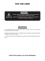
WARNING:
Improper installation, adjustment, alteration, service or maintenance
can cause property damage, injury or death.
Read the Installation and Operating instructions thoroughly before
installing or servicing this equipment.
!

GENERAL
Installation of the unit must be accomplished by quali-
fied electrical installation personnel working to all appli-
cable local and national codes. Improper installation of
product could cause injury or damage.
This equipment is built to comply with applicable stan-
dards for manufacturers. Included among those
approval agencies are: UL, NSF, ASME/Ntl. Bd., CSA,
CGA, ETL, and others. Many local codes exist, and it is
the responsibility of the owner/installer to comply with
these codes.
Note: Maximum voltage for LVD (low volt directive for
Europe) to be 440 volts for CE marked appliances.
INSPECTION / UNPACKING
Note: The electrical rating label is located on the right
console. Serial number, voltage, phase, amperage and
wattage are stated on this label.
1. Before unpacking visually inspect the unit for evi-
dence of damage during shipping.
2. If damage is noticed, do not unpack the unit, follow
"SHIPPING DAMAGE INSTRUCTIONS" shown below.
3. Carefully remove unit from shipping carton. Remove
any packing material from unit. After carefully
unpacking check for "concealed" damage. If dam-
age is noticed, follow "SHIPPING DAMAGE
INSTRUCTIONS" shown below.
4. Check the electrical rating label to ensure that the
unit is the correct voltage, phase, amperage and
wattage are stated on this label.
5. A protective material has been applied to the stain-
less steel panels. This material must be removed
immediately after installation, as heat will melt the
material and make it more difficult to remove.
SHIPPING DAMAGE
INSTRUCTIONS
If shipping damage to the unit is discovered or suspect-
ed, observe the following guidelines in preparing a ship-
ping damage claim.
1. Write down a description of the damage or the rea-
son for suspecting damage as soon as it is discov-
ered. This will help in filling out the claim forms later.
2. As soon as damage is discovered or suspected, noti-
fy the carrier that delivered the shipment.
3. Arrange for the carrier's representative to examine
the damage.
4. Fill out all carrier claims forms and have the examin-
ing carrier sign and date each form.
CLEARANCE REQUIREMENTS
This unit must be installed in accordance with the clear-
ances shown on the rating label which is adhered to the
unit.
FOR YOUR SAFETY. Keep the appliance area free and
clear of combustible materials.
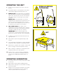
INSTALLATION
Note: For clearance requirements, suggested drain
location and assembly details refer to Specification
Sheet.
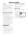
1. Position the unit in it's permanent location, and level
the unit by turning the adjustable feet.
2. Once positioned
and leveled, per-
manently secure
the unit's rear
flanged feet to the
floor using 5/16"
lag bolts and floor
anchors (supplied
by the installer).
Three bolts are
required to secure each of the flanged feet.
3. Seal joints of flanged feet with a silicone sealant.
INSTALLATION
7/16"Ø, 3 HOLES
ON 3 1/8" (80mm) B.C.D.
FLANGED FOOT DETAIL
(REAR LEGS ONLY)
120 120
4 7/8" (124mm)

WIRE CONNECTION
Note: Ensure main power is turned off before connect-
ing wires.
General Information
Install in accordance with local codes and/or the
National Electric Code ANSI/NFPA No. 70-1990 (USA)
or the Canadian Electric Code CSA Standard C22.1
(Canada). A separate fused disconnect switch must be
supplied and installed. The unit must be electrically
grounded by the installer.
The electrical supply must match the power require-
ments specified on the unit's rating label. The copper
wiring must be adequate to carry the required current at
the rated voltage. Wire must be suitable for at least
194°F (90°C). Refer to Specification Sheet for all electri-
cal specifications. Cleveland strongly recommends the
use of liquid tight fittings.
Connection
NOTE: Wiring diagram is located under the top cover of
the unit's right console.
ENSURE THE ELECTRICAL SUPPLY MATCHES THE
UNIT'S REQUIREMENTS AS STATED ON THE ELEC-
TRICAL RATING LABEL.
The supply lines will enter through the bottom of the
right console and are connected to the terminal block.
WATER CONNECTION
(OPTIONAL)
A 1/2" NPT cold water line and/or a 1/2" NPT hot water
line are required if unit is equipped with a single or dou-
ble pantry faucet.
INSTALLATION CHECKS
Although the unit has been thoroughly tested before
leaving the factory, the installer is responsible for ensur-
ing the proper operation of unit once installed.
1. Supply power to the unit by placing the fused dis-
connect switch to the "ON" position.
2. Turn Temperature Dial to 150°F (66°C).
3. Toggle Power Switch to the "ON" position.
4. Heat Indicator Light (yellow) should be ON and unit
heating. When temperature is reached, Yellow
Indicator Light will switch OFF.
7. Turn Temperature Dial 300°F (150°C). Unit will con-
tinue to heat, Heat Indicator Light (yellow) will
remain ON until temperature is reached. Then the
heat indicator light will cycle off indicating the heat-
ing system has shut OFF. The heat indicator light will
continue to cycle ON and OFF as the heating sys-
tem cycles ON and OFF maintaining the desired
temperature.
3. Toggle Power Switch to the "OFF" position.
CLEANING
After installation the unit must be thoroughly cleaned
and sanitized prior to cooking. See “CLEANING
INSTRUCTIONS” in this manual for complete cleaning
instructions.

OPERATING INSTRUCTIONS
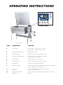
General Parts Drawing
ITEM # DESCRIPTION FUNCTION
1. Power Switch Lower position - power to the unit is OFF.
Upper position - power to the unit is ON.
2. Power Indicator Light (red) Indicates power is ON.
3. Temperature Dial Regulates the surface temperature of the pan.
4. Heat Indicator Light (yellow) Turns ON when system is calling for heat and
OFF when system is satisfied.
5. Hand Tilt Wheel Used for tilting the pan up or down.
6. Power Tilt Switch Option - Used for tilting the pan up or down.
7. Reset Button Fuse protection for optional power tilt.
8. Manual Tilt Override Used on units with optional power tilt for tilting the pan up or down
in case of power or mechanical failure.
9. Faucet Option - hot and/or cold faucet mounts to skillet for
(not shown) convenient filling of the pan.
10. Tangent Draw-Off Valve Option - allows you to discharge product from the pan through
(not shown) the valve.
5
8
4 1 2 3
CONTROL PANEL
7
6

OPERATING THE UNIT
1. Ensure electrical supply to the unit is in the ON
position.
2. Turn Power Switch to the ON position. The yellow
Heat Indicator Light will indicate power is on.
3. MANUAL TILT: Cleveland skillets are equipped
with a manual tilt mechanism for raising and lower-
ing the pan. To raise pan, raise the cover and turn
the crank clockwise. To lower pan, turn counter-
clockwise.
POWER TILT: Cleveland skillets can also be
equipped with an optional electric power tilt mech-
anism for raising and lowering the pan. To raise
pan, raise the cover and press up on the tilt switch.
To lower pan, press down on the tilt switch.
4. FOR YOUR SAFETY: This skillet is also
equipped with a power interrupter which automati-
cally shuts of the power to the elements whenever
the skillet is raised more than 1/2" (13mm).
IMPORTANT: Before commencing to cook,
ensure pan is in the lowered position by pressing
down on the tilt switch. Ensure cover is raised first.
5. To preheat, set Temperature Dial to desired cook-
ing temperature.
6. Allow skillet to preheat for approximately 15-30
minutes.
7. Once preheated, insert product in skillet and adjust
Temperature Dial to required cooking temperature.
8. If desired, once product has cooked, it can be held
prior to serving at a lower temperature setting.
9. When cooking is completed, set Temperature Dial
and Power Switch to the OFF position.
10. The best time to clean the skillet is immediately
after use, once skillet has cooled down. Refer to
section titled "CLEANING INSTRUCTIONS" for
details.
OPERATING SUGGESTION
1. Turn power switch to the "OFF" position when skillet
is not in use.
2. Allow skillet to preheat before adding product.
3. Always lift the spring assist cover before activating
the tilt mechanism.
4. During an electrical power interruption, turn Power
Switch to the OFF position. This unit cannot be
made to operate without electrical power.
1
2
HOT
OPEN LID BEFORE
TILTING PAN
!

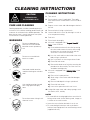
CARE AND CLEANING
Cooking equipment must be cleaned regularly to
maintain its fast, efficient cooking performance and
to ensure its continued safe, reliable operation. The
best time to clean is shortly after each use (allow
unit to cool to a safe temperature).
WARNINGS
➩ Do not use detergents or
cleansers that are chloride
based or contain quaternary
salt.
➩ Do not use a metal bristle
brush or scraper.
➩ Steel wool should never be
used for cleaning the stainless
steel.
➩ Unit should never be cleaned
with a high pressure spray
hose.
➩
Do not leave water sitting in unit
when not in use.
Stagnant
Water
High Pressure
Spray Hose
Chloride Cleaners
Steel Pads
Wire Brush &
CLEANING INSTRUCTIONS
CAUTION
SURFACES MAY
BE EXTREMELY HOT!
CLEANING INSTRUCTIONS
1. Turn unit off.
2. Remove drain screen (if applicable). Thoroughly
wash and rinse the screen either in a sink or a dish-
washer.
3. Prepare a warm water and mild detergent solution in
the unit.
4. Remove food soil using a nylon brush.
5. Loosen food which is stuck by allowing it to soak at
a low temperature setting.
6. Drain unit.
7. Rinse interior thoroughly.
8. If the unit is equipped with a Tangent Draw-Off
Valve, clean as follows:
a) Disassemble the draw-off valve first by turning
the valve knob counter-clockwise, then turning
the large hex nut counter-clockwise until the
valve stem is free of the valve body.
b) In a sink, wash and rinse the inside of the valve
body using a nylon brush.
c)
Use a nylon brush to clean tangent draw-off tube.
d) Rinse with fresh water.
e) Reassemble the draw-off valve by reversing the
procedure for disassembly. The valve's hex nut
should be hand tight only.
9. If the unit is equipped with a Butterfly Valve, clean
as follows:
a) Place valve in open position.
b) Wash using a warm water and mild detergent
solution.
c) Remove food deposits using a nylon brush.
d) Rinse with fresh water.
e) Leave valve open when unit is not in use.
10 . Using mild soapy water and a damp sponge, wash
the exterior, rinse, and dry.
NOTES
➩ For more difficult cleaning applications one of the fol-
lowing can be used: alcohol, baking soda, vinegar, or
a solution of ammonia in water.
➩ Leave the cover off when the kettle is not in use.
➩ For more detailed instructions refer to the Nafem
Stainless Steel Equipment Care and Cleaning manual
(supplied with unit).

STAINLESS STEEL EQUIPMENT CARE AND CLEANING
(Suppied courtesy of Nafem. For more information visit their web site at www.nafem.org)
Contrary to popular belief, stainless steels ARE susceptible to rusting.
Corrosion on metals is everywhere. It is recognized quickly on iron and
steel as unsightly yellow/orange rust. Such metals are called “active”
because they actively corrode in a natural environment when their atoms
combine with oxygen to form rust.
Stainless steels are passive metals because they contain other metals, like
chromium, nickel and manganese that stabilize the atoms. 400 series stain-
less steels are called ferritic, contain chromium, and are magnetic; 300
series stainless steels are called austenitic, contain chromium and nickel;
and 200 series stainless, also austenitic, contains manganese, nitrogen
and carbon. Austenitic types of stainless are not magnetic, and generally
provide greater resistance to corrosion than ferritic types.
With 12-30 percent chromium, an invisible passive film covers the steel’s
surface acting as a shield against corrosion. As long as the film is intact
and not broken or contaminated, the metal is passive and stain-less. If the
passive film of stainless steel has been broken, equipment starts to cor-
rode. At its end, it rusts.
Enemies of Stainless Steel
There are three basic things which can break down stainless steel’s passiv-
ity layer and allow corrosion to occur.
1. Mechanical abrasion
2. Deposits and water
3. Chlorides
Mechanical abrasion means those things that will scratch a steel surface.
Steel pads, wire brushes and scrapers are prime examples.
Water comes out of the faucet in varying degrees of hardness. Depending
on what part of the country you live in, you may have hard or soft water.
Hard water may leave spots, and when heated leave deposits behind that
if left to sit, will break down the passive layer and rust stainless steel. Other
deposits from food preparation and service must be properly removed.
Chlorides are found nearly everywhere. They are in water, food and table
salt. One of the worst chloride perpetrators can come from household and
industrial cleaners.
So what does all this mean? Don’t Despair!
Here are a few steps that can help prevent stainless steel rust.
1.
Use the proper tools.
When cleaning stainless steel products, use non-abrasive tools. Soft
cloths and plastic scouring pads will not harm steel’s passive layer.
Stainless steel pads also can be used but the scrubbing motion must
be in the direction of the manufacturers’ polishing marks.
2.
Clean with the polish lines.
Some stainless steel comes with visible polishing lines or “grain.”
When visible lines are present, always scrub in a motion parallel to the
lines. When the grain cannot be seen, play it safe and use a soft cloth
or plastic scouring pad.
3.
Use alkaline, alkaline chlorinated or non-chloride containing cleaners.
While many traditional cleaners are loaded with chlorides, the industry
is providing an ever-increasing choice of non-chloride cleaners. If you
are not sure of chloride content in the cleaner used, contact your cleaner
supplier. If your present cleaner contains chlorides, ask your supplier if
they have an alternative. Avoid cleaners containing quaternary salts; it
also can attack stainless steel and cause pitting and rusting.
4.
Treat your water.
Though this is not always practical, softening hard water can do much
to reduce deposits. There are certain filters that can be installed to
remove distasteful and corrosive elements. To insure proper water
treatment, call a treatment specialist.
5.
Keep your food equipment clean.
Use alkaline, alkaline chlorinated or non-chloride cleaners at recom-
mended strength. Clean frequently to avoid build-up of hard, stubborn
stains. If you boil water in stainless steel equipment, remember the sin-
gle most likely cause of damage is chlorides in the water. Heating
cleaners that contain chlorides have a similar effect.
6.
Rinse, rinse, rinse.
If chlorinated cleaners are used, rinse and wipe equipment and sup-
plies dry immediately. The sooner you wipe off standing water, espe-
cially when it contains cleaning agents, the better. After wiping equip-
ment down, allow it to air dry; oxygen helps maintain the stainless
steel’s passivity film.
7.
Never use hydrochloric acid (muriatic acid) on stainless steel.
8.
Regularly restore/passivate stainless steel.
Recommended cleaners for specific situations
Job Cleaning Agent Comments
Routine cleaning Soap, ammonia, Apply with cloth or sponge
detergent, Medallion
Fingerprints & smears Arcal 20, Lac-O-Nu Provides barrier film
Ecoshine
Stubborn stains & Cameo, Talc, Zud, Rub in direction of polish lines
discoloration First Impression
Grease & fatty acids, Easy-off, De-Grease Excellent removal on all finishes
blood, burnt-on-foods It Oven Aid
Grease & oil Any good Apply with sponge or cloth
commercial detergent
Restoration/Passivation Benefit, Super Sheen
Review
1. Stainless steels rust when passivity (film-shield) breaks down as a
result of scrapes, scratches, deposits and chlorides.
2. Stainless steel rust starts with pits and cracks.
3. Use the proper tools. Do not use steel pads, wire brushes or scrapers
to clean stainless steel.
4. Use non-chlorinated cleaners at recommended concentrations. Use
only chloride- free cleaners.
5. Soften your water. Use filters and softeners whenever possible.
6. Wipe off cleaning agent(s) and standing water as soon as possible.
Prolonged contact causes eventual problems.
To learn more about chloride-stress corrosion and how to prevent it, con-
tact the equipment manufacturer or cleaning materials supplier.
Developed by Packer Engineering, Naperville, Ill., an independent testing
laboratory.

FAUCET ASSEMBLY
ITEM PART DESCRIPTION QTY.
NO. NO.
1. KE50825-7 3/4" SPOUT . . . . . . . . . . . . . . . . . . . . . . . .1
2. FA95022 RETAINING RING . . . . . . . . . . . . . . . . . . . .1
3. FA05002-19 "O" RING . . . . . . . . . . . . . . . . . . . . . . . . . . .1
4. KE51736 LONG FAUCET NUT . . . . . . . . . . . . . . . . .1
5. SE50020 HOT WATER STEM ASSEMBLY . . . . . . . . .1
(DOUBLE PANTRY ONLY)
6. SE50021 COLD WATER STEM ASSEMBLY . . . . . . . .1
7. KE51401 SINGLE PANTRY BODY . . . . . . . . . . . . . . .1
(C/W ITEM NO. 6)
8. KE50335 ADAPTER WASHER . . . . . . . . . . . . . . . . . .1
(SINGLE PANTRY ONLY)
9. KE51403 DOUBLE PANTRY BODY . . . . . . . . . . . . . .1
(C/W ITEM NO. 5&6)
10. SK00395-1 FAUCET MOUNTING BRACKET . . . . . . . .1
11. FA11258 HEX CAP SCREW . . . . . . . . . . . . . . . . . . .2
12. FA30505-1 WASHER . . . . . . . . . . . . . . . . . . . . . . . . . .2
13. FA21008 HEX NUT . . . . . . . . . . . . . . . . . . . . . . . . . .2
14. SE50447 WASHER HORSESHOE . . . . . . . . . . . . . . .1
1
1
2
2
3
3
4
4
5
9
10
10
13
8
12
11
13
14
12
11
7
6
6
SERVICE PARTS
WARRANTY
Our Company supports a worldwide network of Maintenance and Repair Centers. Contact your nearest
Maintenance and Repair Centre for replacement parts, service, or information regarding the proper mainte-
nance and repair of your cooking equipment
In order to preserve the various agency safety certification (UL, NSF, ASME/Ntl. Bd., etc.), only factory-sup-
plied replacement parts should be used. The use of other than factory supplied replacement parts will void
warranty.

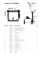
FRAME / LID ASSEMBLY
ITEM NO. PART NO. DESCRIPTION QTY.
1. SK00392-1 FRAME WELDMENT (30 GALLON) . . . . . . . . . . . . . . . . . . . . . . . . . . . . . . . . . .1
SK00392-3 FRAME WELDMENT (40 GALLON) . . . . . . . . . . . . . . . . . . . . . . . . . . . . . . . . . .1
2. SK2457192 LID ASSEMBLY (30 GALLON) . . . . . . . . . . . . . . . . . . . . . . . . . . . . . . . . . . . . . .1
SK2457193 LID ASSEMBLY (40 GALLON) . . . . . . . . . . . . . . . . . . . . . . . . . . . . . . . . . . . . . .1
4. KE50187-1 CAP . . . . . . . . . . . . . . . . . . . . . . . . . . . . . . . . . . . . . . . . . . . . . . . . . . . . . . . . . . .2
5. SK00394-1 HOOK WELDMENT . . . . . . . . . . . . . . . . . . . . . . . . . . . . . . . . . . . . . . . . . . . . . . .2
6. SK2452300 SPRING . . . . . . . . . . . . . . . . . . . . . . . . . . . . . . . . . . . . . . . . . . . . . . . . . . . . . . . .2
7. FA95087-1 EYE BOLT . . . . . . . . . . . . . . . . . . . . . . . . . . . . . . . . . . . . . . . . . . . . . . . . . . . . . .2
8. FA20008 HEX NUT . . . . . . . . . . . . . . . . . . . . . . . . . . . . . . . . . . . . . . . . . . . . . . . . . . . . . . .2
9. KE53573-1 BEARING . . . . . . . . . . . . . . . . . . . . . . . . . . . . . . . . . . . . . . . . . . . . . . . . . . . . . . .2
10. FA15019-4 SHOULDER BOLT . . . . . . . . . . . . . . . . . . . . . . . . . . . . . . . . . . . . . . . . . . . . . . . .2
11. FA21501-2 ACORN NUT . . . . . . . . . . . . . . . . . . . . . . . . . . . . . . . . . . . . . . . . . . . . . . . . . . . .2
12. KE00099 ADJUSTABLE FOOT (FLANGED) . . . . . . . . . . . . . . . . . . . . . . . . . . . . . . . . . . . .2
13. KE50249-1 FOOT ADJUSTOR (W/O FLANGE) . . . . . . . . . . . . . . . . . . . . . . . . . . . . . . . . . . .2
17. FA31029 LOCKWASHER . . . . . . . . . . . . . . . . . . . . . . . . . . . . . . . . . . . . . . . . . . . . . . . . . .2
18. FA11054 SCREW . . . . . . . . . . . . . . . . . . . . . . . . . . . . . . . . . . . . . . . . . . . . . . . . . . . . . . . .4
19. SK2459299 COUPLING ASSEMBLY . . . . . . . . . . . . . . . . . . . . . . . . . . . . . . . . . . . . . . . . . . . .1
20 FA21024 HEX NUT (5/16-18) . . . . . . . . . . . . . . . . . . . . . . . . . . . . . . . . . . . . . . . . . . . . . . .2
21. FA31030 LOCKWASHER . . . . . . . . . . . . . . . . . . . . . . . . . . . . . . . . . . . . . . . . . . . . . . . . . .2
22. FA30055 FLAT WASHER . . . . . . . . . . . . . . . . . . . . . . . . . . . . . . . . . . . . . . . . . . . . . . . . . .2
23. SK00054 VENT COVER ASSEMBLY . . . . . . . . . . . . . . . . . . . . . . . . . . . . . . . . . . . . . . . . . .1
24. SK2211200 SPACER . . . . . . . . . . . . . . . . . . . . . . . . . . . . . . . . . . . . . . . . . . . . . . . . . . . . . . . .1
25. FA95081-1 BOLT, MODIFIED . . . . . . . . . . . . . . . . . . . . . . . . . . . . . . . . . . . . . . . . . . . . . . . . .1
26. SK50179 WASHER . . . . . . . . . . . . . . . . . . . . . . . . . . . . . . . . . . . . . . . . . . . . . . . . . . . . . . .1
27. FA30504 WASHER . . . . . . . . . . . . . . . . . . . . . . . . . . . . . . . . . . . . . . . . . . . . . . . . . . . . . . .2
9
19 120 21 22
23
2
13 12
24 25 26
10
11
17
4 18
6
7
8
27
5
OPEN END OF
SPRING TO BE
LOCATED ON TO
P
APPLY
REMOVABLE
LOCKTITE

1
2
3
4
5
6
7
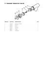
2" TANGENT DRAW-OFF VALVE
ITEM NO. PART NO. DESCRIPTION QTY.
1. - 7. KE50972-B DRAW-OFF ASSEMBLY . . . . . . . . . . . . . . . . . . . . . . . . . . . . . . . . . . . . . . . . . . . .1
1. FA95049 WING NUT . . . . . . . . . . . . . . . . . . . . . . . . . . . . . . . . . . . . . . . . . . . . . . . . . . . . . .1
2. KE527551 KNOB . . . . . . . . . . . . . . . . . . . . . . . . . . . . . . . . . . . . . . . . . . . . . . . . . . . . . . . . .1
3. KE52754 HEX NUT . . . . . . . . . . . . . . . . . . . . . . . . . . . . . . . . . . . . . . . . . . . . . . . . . . . . . . .1
4. KE52753 RETAINER . . . . . . . . . . . . . . . . . . . . . . . . . . . . . . . . . . . . . . . . . . . . . . . . . . . . . .1
5. KE52752 PISTON . . . . . . . . . . . . . . . . . . . . . . . . . . . . . . . . . . . . . . . . . . . . . . . . . . . . . . . .1
6. FA00111 "O" RING . . . . . . . . . . . . . . . . . . . . . . . . . . . . . . . . . . . . . . . . . . . . . . . . . . . . . . .1
7. KE52751 VALVE BODY . . . . . . . . . . . . . . . . . . . . . . . . . . . . . . . . . . . . . . . . . . . . . . . . . . .2

9
47
3
20
116
15
14
13
5
66
11 171819 16 12 2548
9
43 42 41
47
40
39
4
20
*116
26
22 23
4415
6
16
17
21
18 19
23 22
3
20
116
15
14
13
353634
11 171819 20 37
9 5
7
6
8
32
47
9 47
24 25
4
38
12
15 16
33 29 51
20
*116
26
22 23
16
23 1022
10 0
23 75 45 29 51
MANUAL
TILT
POWER
TILT
20 49 50 24
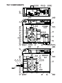
TILT COMPONENTS

ITEM NO. PART NO. DESCRIPTION QTY.
3. REF.SK00387 GEARBOX COVER ASSEMBLY . . . . . . . . . . . . . . . . . . . . . . . . . . . . . . . . . . . . . 1
4. KE002590 WRAP WELDMENT FOR GEAR . . . . . . . . . . . . . . . . . . . . . . . . . . . . . . . . . . . . . 1
5. KE55513 GEAR BOX . . . . . . . . . . . . . . . . . . . . . . . . . . . . . . . . . . . . . . . . . . . . . . . . . . . . 1
6. KE602239 STOP ARM . . . . . . . . . . . . . . . . . . . . . . . . . . . . . . . . . . . . . . . . . . . . . . . . . . . . . 1
7. KE602587 SAFETY MOUNTING BRACKET . . . . . . . . . . . . . . . . . . . . . . . . . . . . . . . . . . . . 1
8. KE602598 MOUNTING BRACKET . . . . . . . . . . . . . . . . . . . . . . . . . . . . . . . . . . . . . . . . . . . . 1
9. SK2474500 SWTCH, TILT LIMIT . . . . . . . . . . . . . . . . . . . . . . . . . . . . . . . . . . . . . . . . . . . . . . 1
10. REF.SK00410 COMPONENT PLATE ASSEMBLY . . . . . . . . . . . . . . . . . . . . . . . . . . . . . . . . . . . 1
11. FA95055-13 KEY, 3/8 X 3/8 X 5 . . . . . . . . . . . . . . . . . . . . . . . . . . . . . . . . . . . . . . . . . . . . . . . 1
12. FA15019-6 SHOULDER BOLT . . . . . . . . . . . . . . . . . . . . . . . . . . . . . . . . . . . . . . . . . . . . . . . 1
13 FA21024 5-16 HEX NUT, 18-8 S.S. . . . . . . . . . . . . . . . . . . . . . . . . . . . . . . . . . . . . . . . . . . 1
14. KE002527 STOP ASSEMBLY . . . . . . . . . . . . . . . . . . . . . . . . . . . . . . . . . . . . . . . . . . . . . . . 1
15. FA15021 BOLT, HEX CAP M10 X 30 . . . . . . . . . . . . . . . . . . . . . . . . . . . . . . . . . . . . . . . . 2
16. FA31500 LOCKWASHER, M10 . . . . . . . . . . . . . . . . . . . . . . . . . . . . . . . . . . . . . . . . . . . . . 2
17. FA11526 HEX. CAP SCREW, 7/16-14 X 1-1/4" S.S. 18-8 . . . . . . . . . . . . . . . . . . . . . . . . . 6
18. FA31011 7/16 SPLIT LOCKWASHER, S.S. 18-8 . . . . . . . . . . . . . . . . . . . . . . . . . . . . . . . . 6
19. FA21506 NUT, 7/16-14 S.S. 18-8 . . . . . . . . . . . . . . . . . . . . . . . . . . . . . . . . . . . . . . . . . . . . 6
20. FA11135 SCREW, 10-24 X 1/2 . . . . . . . . . . . . . . . . . . . . . . . . . . . . . . . . . . . . . . . . . . . . . . 7
21. KE602573 MOUNTING BRACKET . . . . . . . . . . . . . . . . . . . . . . . . . . . . . . . . . . . . . . . . . . . . 1
22. FA21008 HEX. NUT, 1/4-20 . . . . . . . . . . . . . . . . . . . . . . . . . . . . . . . . . . . . . . . . . . . . . . . . 6
23. FA31029 SPLIT LOCKWASHER, 1/4 . . . . . . . . . . . . . . . . . . . . . . . . . . . . . . . . . . . . . . . . . 6
24. FA21024 5/16 - 18, HEX NUT, 18-8 S.S. . . . . . . . . . . . . . . . . . . . . . . . . . . . . . . . . . . . . . . 4
25. FA31030 SPLIT LOCKWASHER, 5/16 . . . . . . . . . . . . . . . . . . . . . . . . . . . . . . . . . . . . . . . . 4
26. KE600284-4 GASKET, SILICONE GRAY . . . . . . . . . . . . . . . . . . . . . . . . . . . . . . . . . . . . . . . . . 1
29. FA31031 SPLIT LOCKWAHER . . . . . . . . . . . . . . . . . . . . . . . . . . . . . . . . . . . . . . . . . . . . . . 2
32. KE002215 STOP ARM . . . . . . . . . . . . . . . . . . . . . . . . . . . . . . . . . . . . . . . . . . . . . . . . . . . . . 1
33. FA19196 SET SCREW, 3/8-16 X 2 1/2" . . . . . . . . . . . . . . . . . . . . . . . . . . . . . . . . . . . . . . . 1
34. KE002509 HAND CRANK ASSEMBLY . . . . . . . . . . . . . . . . . . . . . . . . . . . . . . . . . . . . . . . . 1
35. KE54738-5 WASHER, FLAT . . . . . . . . . . . . . . . . . . . . . . . . . . . . . . . . . . . . . . . . . . . . . . . . . . 1
36. FA19505 SET SCREW, 3/8-24 X 3/8” . . . . . . . . . . . . . . . . . . . . . . . . . . . . . . . . . . . . . . . . . 1
37. KE602511 BOTTOM COVER . . . . . . . . . . . . . . . . . . . . . . . . . . . . . . . . . . . . . . . . . . . . . . . . 1
38. KE602032 SPACER . . . . . . . . . . . . . . . . . . . . . . . . . . . . . . . . . . . . . . . . . . . . . . . . . . . . . . . 1
39. KE601725 SUPPORT . . . . . . . . . . . . . . . . . . . . . . . . . . . . . . . . . . . . . . . . . . . . . . . . . . . . . . 1
40. KE52832-5 MOTOR, POWER TILT . . . . . . . . . . . . . . . . . . . . . . . . . . . . . . . . . . . . . . . . . . . . 1
41. KE50582-5 COUPLING HUB, 1/2 BORE . . . . . . . . . . . . . . . . . . . . . . . . . . . . . . . . . . . . . . . . 1
42. KE50583-1 COUPLING SPIDER . . . . . . . . . . . . . . . . . . . . . . . . . . . . . . . . . . . . . . . . . . . . . . 1
43. KE50582-4 COUPLING HUB, 3/4 BORE . . . . . . . . . . . . . . . . . . . . . . . . . . . . . . . . . . . . . . . . 1
44. KE601886 STOP . . . . . . . . . . . . . . . . . . . . . . . . . . . . . . . . . . . . . . . . . . . . . . . . . . . . . . . . . . 1
45. FA11384 HEX. CAP SCREW, 3/8-16 X 1” . . . . . . . . . . . . . . . . . . . . . . . . . . . . . . . . . . . . . 2
47. FA10140 SCREW, 6-32 X 1 1/4 . . . . . . . . . . . . . . . . . . . . . . . . . . . . . . . . . . . . . . . . . . . . . 2
48. KE602542 EXTENSION FOR SHAFT . . . . . . . . . . . . . . . . . . . . . . . . . . . . . . . . . . . . . . . . . 1
49. KE602543 SOCKET SET SCREW, CONE POINT . . . . . . . . . . . . . . . . . . . . . . . . . . . . . . . . . 1
50. KE602507 BOTTOM COVER . . . . . . . . . . . . . . . . . . . . . . . . . . . . . . . . . . . . . . . . . . . . . . . . 1
51. FA21026 3/8 HEXAGON NUT . . . . . . . . . . . . . . . . . . . . . . . . . . . . . . . . . . . . . . . . . . . . . . 2
66. KE602571 MOUNTING BRACKET . . . . . . . . . . . . . . . . . . . . . . . . . . . . . . . . . . . . . . . . . . . . 1
75. FA11258 1/4-20 X 3/4 BOLT, 18-8 S.S. . . . . . . . . . . . . . . . . . . . . . . . . . . . . . . . . . . . . . . . 4
100. FA30505-1 FLAT WASHER, 1/4 . . . . . . . . . . . . . . . . . . . . . . . . . . . . . . . . . . . . . . . . . . . . . . 4
116. FA11511-2 10-32 X 3/8 PAN HEAD TORX SCREW . . . . . . . . . . . . . . . . . . . . . . . . . . . . . . . 1
TILT COMPONENTS

1 2
11
9
12
15
10
14
13
3 4
5 6
7
8
8
9
9
16
SECTION
A - A
SECTION
B - B
SECTION
C - C
BA
AB
C
C
WARNING:
Improper installation,
adjustment, alteration, service or
maintenance can cause property
damage, injury or death. Read the
installation, operating and maintenance
instructions thoroughly before installing
or servicing this equipment.
AVERTISSEMENT: Une mauvaise
installation, un réglage inadapté ou
un manque d'entretien peuvent
occasionner des dommages
matériels ou corporels. Il est donc
indispensable de lire attentivement
les notices avant l'installation ou
l'entretien.
WARNUNG: Unsachgemäßer Einbau,
Einstellung, Veränderung, Bedienung oder
Wartung können Sachschaden,
Verletzungen oder Tod verursachen. Lesen
Sie bitte die Einbau-, Bedienungs- und
Wartungsanleitungen genau durch, ehe Sie
dieses Gerät einbauen oder bedienen.
ADVERTENCIA: La instalación, ajuste,
alteración, servicio o mantenimiento
incorrectos pueden causar daños a la
propiedad, lesiones o muerte. Lea
detenidamente las instrucciones de
instalación, operación y mantenimiento antes
de instalar o dar servicio a este equipo.
ATTENZIONE:
Installazione, regolazione,
modifiche, riparazioni o manutenzione
erronee possono causare danni, infortuni o
morte. Leggere attentamente le istruzioni per
l'installazione, il funzionamento e la
manutenzione prima di installare o riparare
questo macchinario
.
HOT
CHAUD
1
2
!
SK95063
17
18
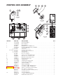
CONTROL BOX ASSEMBLY
ITEM NO. PART NO. DESCRIPTION QTY.
1. SK2138700 KNOB ASSEMBLY . . . . . . . . . . . . . . . . . . . . . . . . . . . . . . . . . . . . . . . . . . . . . . . .1
2. SK2360700 DIAL INSERT °F . . . . . . . . . . . . . . . . . . . . . . . . . . . . . . . . . . . . . . . . . . . . . . . . .1
SK2360701 DIAL INSERT °C . . . . . . . . . . . . . . . . . . . . . . . . . . . . . . . . . . . . . . . . . . . . . . . . .1
3. KE51005 RUBBER BOOT. #N9030 X 1/4 . . . . . . . . . . . . . . . . . . . . . . . . . . . . . . . . . . . . . .1
4. SK2498399 POTENTIOMETER SHAFT ASSEMBLY . . . . . . . . . . . . . . . . . . . . . . . . . . . . . . . .1
SK2166800 POTENTIOMETER SHAFT . . . . . . . . . . . . . . . . . . . . . . . . . . . . . . . . . . . . . . . . . . . . . . . . . . . . . . . . . . . .1
SK2167000 TENSION PIN . . . . . . . . . . . . . . . . . . . . . . . . . . . . . . . . . . . . . . . . . . . . . . . . . . . . . . . . . . . . . . . . . . . . .1
SK2167100 WASHER, BOWED/SPRING . . . . . . . . . . . . . . . . . . . . . . . . . . . . . . . . . . . . . . . . . . . . . . . . . . . . . . . . . .1
SK2167200 RETAINING RING, SP-NR #R1000-25 . . . . . . . . . . . . . . . . . . . . . . . . . . . . . . . . . . . . . . . . . . . . . . . . . . .1
SK2167300 PANEL BEARING . . . . . . . . . . . . . . . . . . . . . . . . . . . . . . . . . . . . . . . . . . . . . . . . . . . . . . . . . . . . . . . . . . .1
SK2382800 RETAINING RING CLIP . . . . . . . . . . . . . . . . . . . . . . . . . . . . . . . . . . . . . . . . . . . . . . . . . . . . . . . . . . . . . .1
5. FA21006 NUT, S.S. F#10-24 . . . . . . . . . . . . . . . . . . . . . . . . . . . . . . . . . . . . . . . . . . . . . . . .2
6. FA32022 TOOTH LOCK WASHER #10 S.S. . . . . . . . . . . . . . . . . . . . . . . . . . . . . . . . . . . .2
7. FA40000-6 #10-24 X 3/8 S.S. WELD STUD . . . . . . . . . . . . . . . . . . . . . . . . . . . . . . . . . . . . . .2
8. SK50903-1 BRACKET, INDICATOR LIGHT . . . . . . . . . . . . . . . . . . . . . . . . . . . . . . . . . . . . . .1
9. SK50905-1 HEAT INDICATOR, 28V . . . . . . . . . . . . . . . . . . . . . . . . . . . . . . . . . . . . . . . . . . . .1
10. SK2142002 THERMOSTAT . . . . . . . . . . . . . . . . . . . . . . . . . . . . . . . . . . . . . . . . . . . . . . . . . . .1
11. SK2159300 THERMOSTAT INSULATOR . . . . . . . . . . . . . . . . . . . . . . . . . . . . . . . . . . . . . . . . .1
12. SK2491500 STOP PLATE ASSEMBLY . . . . . . . . . . . . . . . . . . . . . . . . . . . . . . . . . . . . . . . . . .1
13. SK95063 CAUTION LABEL . . . . . . . . . . . . . . . . . . . . . . . . . . . . . . . . . . . . . . . . . . . . . . . .1
14. SK90126-2 WIRING DIAGRAM . . . . . . . . . . . . . . . . . . . . . . . . . . . . . . . . . . . . . . . . . . . . . . .1
15. KE95604-3 CONTROLS LABEL, MANUAL TILT . . . . . . . . . . . . . . . . . . . . . . . . . . . . . . . . . .1
KE95604-4 CONTROLS LABEL, POWER TILT . . . . . . . . . . . . . . . . . . . . . . . . . . . . . . . . . . .1
16. SK2474102 SWITCH, ON/OFF/ON, DUAL FIRING . . . . . . . . . . . . . . . . . . . . . . . . . . . . . . . . .1
17. KE53137-3 TILT SWITCH, ON/OFF/ON . . . . . . . . . . . . . . . . . . . . . . . . . . . . . . . . . . . . . . . . .1
KE53184 CONTACT SECTION HOLDER (LATCH) . . . . . . . . . . . . . . . . . . . . . . . . . . . . . . .1
KE53138-1 CONTACT BLOCK . . . . . . . . . . . . . . . . . . . . . . . . . . . . . . . . . . . . . . . . . . . . . . .4
18. KE50579-2 CIRCUIT BREAKER . . . . . . . . . . . . . . . . . . . . . . . . . . . . . . . . . . . . . . . . . . . . . . .1
FA05002-34 "O" RING, CIRCUIT BREAKER . . . . . . . . . . . . . . . . . . . . . . . . . . . . . . . . . . . . . .1
KE50580 WATER RESISTANT BOOT . . . . . . . . . . . . . . . . . . . . . . . . . . . . . . . . . . . . . . . . .1
{
INCLUDES
SK2474103

1
7
8
9
5
14
3
11
21
3
11
12
6 15 16
4 13
9 18 19
20 9
9
9
10
2
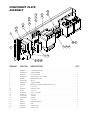
COMPONENT PLATE
ASSEMBLY
ITEM NO. PART NO. DESCRIPTION QTY.
1. KE602092 COMPONENT PLATE . . . . . . . . . . . . . . . . . . . . . . . . . . . . . . . . . . . . . . . . . . . . . . . . . 1
2. KE53838-10 TRANSFORMER . . . . . . . . . . . . . . . . . . . . . . . . . . . . . . . . . . . . . . . . . . . . . . . . . . . . .1
3. KE51139 FUSE HOLDER . . . . . . . . . . . . . . . . . . . . . . . . . . . . . . . . . . . . . . . . . . . . . . . . . . 2
4. KE50753-10 RELAY, DTDP / 10A / 120VAC . . . . . . . . . . . . . . . . . . . . . . . . . . . . . . . . . . . . . . . . . . 2
5. KE50581 BRIDGE RECTIFIER . . . . . . . . . . . . . . . . . . . . . . . . . . . . . . . . . . . . . . . . . . . . . . . . . .1
6. SK2475500 RELAY . . . . . . . . . . . . . . . . . . . . . . . . . . . . . . . . . . . . . . . . . . . . . . . . . . . . . . . . . . . . . 1
7. KE53838-25 TRANSFORMER . . . . . . . . . . . . . . . . . . . . . . . . . . . . . . . . . . . . . . . . . . . . . . . . . . . . .1
8. KE53444 BRACKET, TRANSFORMER MOUNTING . . . . . . . . . . . . . . . . . . . . . . . . . . . . . . 1
9. F10 8-32 X 3/8 . . . . . . . . . . . . . . . . . . . . . . . . . . . . . . . . . . . . . . . . . . . . . . . . . . . . . . 3
10. KE50473 GROUND LUG . . . . . . . . . . . . . . . . . . . . . . . . . . . . . . . . . . . . . . . . . . . . . . . . . .1
11. FA904 6-32 x 5/8 . . . . . . . . . . . . . . . . . . . . . . . . . . . . . . . . . . . . . . . . . . . . . . . . . . . . . . . . . . 2
12. KE52936-8 FUSE, 1.25 AMP. . . . . . . . . . . . . . . . . . . . . . . . . . . . . . . . . . . . . . . . . . . . . . . . . . 1
14. FA15018-8 8-32 X 1 . . . . . . . . . . . . . . . . . . . . . . . . . . . . . . . . . . . . . . . . . . . . . . . . . . . . . . . . . . . .1
15. SK2475600 HOLDER . . . . . . . . . . . . . . . . . . . . . . . . . . . . . . . . . . . . . . . . . . . . . . . . . . . . . . . . . . . 1
16. SK2475700 SPRING . . . . . . . . . . . . . . . . . . . . . . . . . . . . . . . . . . . . . . . . . . . . . . . . . . . . . . . . . . . . 1
17. F904 6-32 X 5/8 . . . . . . . . . . . . . . . . . . . . . . . . . . . . . . . . . . . . . . . . . . . . . . . . . . . . . . . . . . 2
18. KE50577 TERMINAL BLOCK . . . . . . . . . . . . . . . . . . . . . . . . . . . . . . . . . . . . . . . . . . . . . . . . . . . 3
19. KE50576 END . . . . . . . . . . . . . . . . . . . . . . . . . . . . . . . . . . . . . . . . . . . . . . . . . . . . . . . . . . . . . . . 1
20. KE50750-7 CONTACTOR . . . . . . . . . . . . . . . . . . . . . . . . . . . . . . . . . . . . . . . . . . . . . . . . . . . . . . . 2
21. KE52936-6 FUSE, 3 AMP . . . . . . . . . . . . . . . . . . . . . . . . . . . . . . . . . . . . . . . . . . . . . . . . . . . . . . . 1

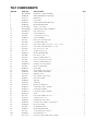
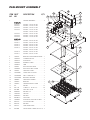
PAN MOUNT ASSEMBLY
ITEM PART DESCRIPTION QTY.
NO. NO.
1. HEATING ELEMENTS . . . . . . . . . . . .6
30 GALLON
SK50845-1 ELEMENT, 2.00 KW, 480 VAC
SK50845-2 ELEMENT, 2.67 KW, 416 VAC
SK50845-3 ELEMENT, 2.00 KW, 416 VAC
SK50845-4 ELEMENT, 2.67 KW, 240 VAC
ELEMENT, 2.00 KW, 208 VAC
SK50845-5 ELEMENT, 2.00 KW, 240 VAC
SK50845-6 ELEMENT, 2.67 KW, 208 VAC
SK50845-8 ELEMENT, 2.67 KW, 480 VAC
40 GALLON
SK50861-1 ELEMENT, 4.00 KW, 480 VAC
SK50861-2 ELEMENT, 3.00 KW, 480 VAC
SK50861-3 ELEMENT, 4.00 KW, 416 VAC
SK50861-4 ELEMENT, 3.00 KW, 416 VAC
SK50861-5 ELEMENT, 4.00 KW, 240 VAC
ELEMENT, 3.00 KW, 208 VAC
SK50861-6 ELEMENT, 3.00 KW, 240 VAC
SK50861-7 ELEMENT, 4.00 KW, 208 VAC
3. SK50932 BRACKET FOR THERMOCOUPLE . .1
4. SK50958-1 CLAMPING PLATE . . . . . . . . . . . . . . .1
5. SK50959-1 INSULATION . . . . . . . . . . . . . . . . . . .1
6. SK50960-1 ELEMENT COVER . . . . . . . . . . . . . . .1
7. SK50862-1 TRIM . . . . . . . . . . . . . . . . . . . . . . . . .1
8. SK50961 ELECTRIC BOX WRAP . . . . . . . . . . .1
9. SK50850-1 ELECTRICAL BOX COVER . . . . . . . .1
10. SK50965 SIDE BOX COVER . . . . . . . . . . . . . . .1
11. SK2489001 LIQUID TIGHT FITTING . . . . . . . . . . .1
12. SK2490600 FULL COUPLING S.S. . . . . . . . . . . . .1
13. SK2487800 BAYONET, ADAPTER . . . . . . . . . . . . .1
14. SK00409 SIDE BOX ASSEMBLY . . . . . . . . . . . .1
15. SK50963 BRACKET . . . . . . . . . . . . . . . . . . . . .1
16. SK50962 THERMOCOUPLE COVER . . . . . . . .1
17. F95 PALNUT . . . . . . . . . . . . . . . . . . . . . .91
18. FA11144 SCREW, S.S. 10-32 X 1/4 . . . . . . . .46
19. FA21008 HEX. NUT 1/4-20 . . . . . . . . . . . . . . . .3
20. FA30505-1 WASHER, 1/4 . . . . . . . . . . . . . . . . . . .3
21. SK50933-1 SENSOR . . . . . . . . . . . . . . . . . . . . . .1
22. FA30505-3 WASHER . . . . . . . . . . . . . . . . . . . . . .1
23. KE55069-7 HIGH LIMIT . . . . . . . . . . . . . . . . . . . .1
24. SK50908-1 INSULATION, ELECTRICAL BOX . . .2
26. KE55247 SILICON WASHER . . . . . . . . . . . . . . .2
27. KE53735 WASHER . . . . . . . . . . . . . . . . . . . . . .1
28. 54833-4 SNAP-IN BUSHING . . . . . . . . . . . . . .2
29. FA95088 HEX FLANGE, SCREW, 10-32 X 1/2 .2
24
12
12
18
28
9
24
8
17
7
18
5
4
1
26
16
22
13
21
10 271811
14
23
18
19
20
19
20
15
6
3
29

WARNING:
Any maintenance or service involving disassembly of components
should be made by a qualified service technician. Ensure electrical
and water supply (if applicable) to the unit are shut off.
!
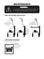
HINGE ADJUSTMENT INSTRUCTIONS
1.
FULLY LIFT COVER
TO RELEASE SPRING
TENSION
SPRING
3.
WHEN PROPERLY
ADJUSTED, COVER
SHOULD REST AT 70˚
2.
USING A
7/16" DEEP
SOCKET
ADJUST LEFT
AND RIGHT
BOLTS
EVENLY
MAINTENANCE
LUBRICATION PROCEDURE
Lubricate the following parts every three months to
insure smooth operation and reduce wear.
TRUNNIONS
On the left hand side of
the skillet there are two
grease nipples on the
top back portion of the
trunnion housing.
Trunnion Housing
Grease Nipple

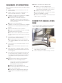
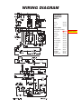
SEQUENCE OF OPERATIONS
When using these instructions refer to the SEL-TI wiring
schematic.
1. Supply Voltage is sent to the primary of the 120
VAC transformer.
2. Supply voltage is sent to the normally open con-
tacts of the Heat Contactors, C1 and C2.
3. 120 VAC is sent from the secondary of the 120VAC
transformer through the 3 amp fuse to
■ The primary of the 24 VAC transformer
❏ 24 VAC is sent from the secondary of the
24VAC transformer through the 1.25 amp fuse
to the on/off switch.
■ Contacts of the R1 Heat Relay
4. 120 VAC is sent from the secondary of the 120 VAC
transformer to the optional Power Tilt Circuit (See
step 9).
5. With the On/Off switch in the On position.
■ 24 VAC is sent through the normally closed high
limit switch to the mercury switch..
■ If the skillet is in the down position then 24 VAC
is sent through mercury switch to pin 9 on the ther-
mostat.
6. If the steamer is calling for heat the 24 VAC is sent
from pin number 10 to RI Heat Relay.
■ The normally open contacts of the Heat relay
close sending 120 VAC to the Heat contactor coils
C 1 and C2.
7. The Contactor close and supply Voltage is sent to
the elements.
■ The elements heat until the thermostat is satis-
fied.
8. When thermostat is satisfied, 24 VAC is removed
from pin 10 on the thermostat and the heat circuit
is de-energized.
9. If the skillet has the optional Power Tilt option and
is in the down position, 120 VAC is sent from the
secondary of the 120 VAC transformer through the
circuit breaker and the up limit switch to the tilt
switch.
10. With the tilt switch in switch in the Up position
■ 120 VAC is sent to the Bridge Rectifier
❏ 115 VDC is sent from the rectifier through
the 30-ohm resistor to the normally open
RY10 and RYI I relay contacts.
■ 120 VAC is sent to the RY10 relay coil.
■ The normally open RY10 contact close and 90
VDC is sent to the DC motor
■ The DC motor is energized and the skillet tilts
until the switch is released or the up limit switch
opens.
11. With the Tilt switch in the Down position
■ 120 VAC is sent to the Bridge Rectifier
❏ 115 DC is sent from the rectifier to the nor-
mally open RY 10 and RY 11 relay contacts.
■ 120 VAC is sent to the RY11 relay coil.
■ The normally open RY 11 contact close and the
polarity of the 90 VDC is reversed.
■ The DC motor is energized and the skillet lowers
until the switch is released or
POWER TILT MANUAL OVER-
RIDE
In case of power failure or malfunction the skillet pan
can be tilted manually following these instructions.
1. Fit a 1/2” SIX POINT SOCKET over the MANUAL
TILT SHAFT as shown above.
2. Turn socket wrench clockwise to empty contents.
MANUAL
TILT
SHAFT
1/2”
SIX POINT
SOCKET

PART NO. DESCRIPTION QTY.
HEATING ELEMENTS
. . . . . . . . . . . . . . . . . . . . . . . . . . . . . . . . . . . . . . . . . . . . . . . . . . . . . . . . . . . . . . . . . . . . . . . . . . . . . . . . . . . . . . . . . . . . 6
30 GALLON
SK50845-1 ELEMENT, 2.00 KW, 480 VAC
SK50845-2 ELEMENT, 2.67 KW, 416 VAC
SK50845-3 ELEMENT, 2.00 KW, 416 VAC
SK50845-4 ELEMENT, 2.67 KW, 240 VAC
ELEMENT, 2.00 KW, 208 VAC
SK50845-5 ELEMENT, 2.00 KW, 240 VAC
SK50845-6 ELEMENT, 2.67 KW, 208 VAC
SK50845-8 ELEMENT, 2.67 KW, 480 VAC
40 GALLON
SK50861-1 ELEMENT, 4.00 KW, 480 VAC
SK50861-2 ELEMENT, 3.00 KW, 480 VAC
SK50861-3 ELEMENT, 4.00 KW, 416 VAC
SK50861-4 ELEMENT, 3.00 KW, 416 VAC
SK50861-5 ELEMENT, 4.00 KW, 240 VAC
ELEMENT, 3.00 KW, 208 VAC
SK50861-6 ELEMENT, 3.00 KW, 240 VAC
SK50861-7 ELEMENT, 4.00 KW, 208 VAC
SK2474500 SWTCH, TILT LIMIT . . . . . . . . . . . . . . . . . . . . . . . . . . . . . . . . . . . . . . . . . . . . . . . . . . . . . . . . . . . . . . . . . . . . . . .1
SK50933-1 SENSOR . . . . . . . . . . . . . . . . . . . . . . . . . . . . . . . . . . . . . . . . . . . . . . . . . . . . . . . . . . . . . . . . . . . . . . . . . . . . . . . . . . . . .1
KE55069-7 SAFETY THERMOSTAT . . . . . . . . . . . . . . . . . . . . . . . . . . . . . . . . . . . . . . . . . . . . . . . . . . . . . . . . . . . . . . . . . . . . . . . . . .1
SK2475500 RELAY . . . . . . . . . . . . . . . . . . . . . . . . . . . . . . . . . . . . . . . . . . . . . . . . . . . . . . . . . . . . . . . . . . . . . . . . . . . . . . . . . . . . . . .1
KE50750-7 CONTACTOR . . . . . . . . . . . . . . . . . . . . . . . . . . . . . . . . . . . . . . . . . . . . . . . . . . . . . . . . . . . . . . . . . . . . . . . . . . . . . . . . .2
KE53838-10 TRANSFORMER, 208-240V, 480V . . . . . . . . . . . . . . . . . . . . . . . . . . . . . . . . . . . . . . . . . . . . . . . . . . . . . . . . . . . . . . . . . .1
KE53838-11 TRANSFORMER, 380-415V . . . . . . . . . . . . . . . . . . . . . . . . . . . . . . . . . . . . . . . . . . . . . . . . . . . . . . . . . . . . . . . . . . . . . . .1
KE53838-25 TRANSFORMER . . . . . . . . . . . . . . . . . . . . . . . . . . . . . . . . . . . . . . . . . . . . . . . . . . . . . . . . . . . . . . . . . . . . . . . . . . . . . . .1
KE52936-8 FUSE, 1.25 AMP . . . . . . . . . . . . . . . . . . . . . . . . . . . . . . . . . . . . . . . . . . . . . . . . . . . . . . . . . . . . . . . . . . . . . . . . . . . . . . .1
KE52936-6 FUSE, 3 AMP . . . . . . . . . . . . . . . . . . . . . . . . . . . . . . . . . . . . . . . . . . . . . . . . . . . . . . . . . . . . . . . . . . . . . . . . . . . . . . . . . .1
SK2498399 POTENTIOMETER SHAFT ASSEMBLY . . . . . . . . . . . . . . . . . . . . . . . . . . . . . . . . . . . . . . . . . . . . . . . . . . . . . . . . .1
INCLUDES:
. . . . . . . . . . . . . . . . . . . . . . . . . . . . . . . . . . . . . . . . . . . . . . . . . . . . . . . . . . . . . . . . . . . . . . . . . . . . . . . . . . . . . . . . . . .
SK2166800 POTENTIOMETER SHAFT . . . . . . . . . . . . . . . . . . . . . . . . . . . . . . . . . . . . . . . . . . . . . . . . . . . . . . . . . . . . . . . . . . . . . . . . . . . . . . .1
SK2167000 TENSION PIN . . . . . . . . . . . . . . . . . . . . . . . . . . . . . . . . . . . . . . . . . . . . . . . . . . . . . . . . . . . . . . . . . . . . . . . . . . . . . . . . . . . . . . . . .1
SK2167100 WASHER, BOWED/SPRING . . . . . . . . . . . . . . . . . . . . . . . . . . . . . . . . . . . . . . . . . . . . . . . . . . . . . . . . . . . . . . . . . . . . . . . . . . . . .1
SK2167200 RETAINING RING, SP-NR #R1000-25 . . . . . . . . . . . . . . . . . . . . . . . . . . . . . . . . . . . . . . . . . . . . . . . . . . . . . . . . . . . . . . . . . . . . . .1
SK2167300 PANEL BEARING . . . . . . . . . . . . . . . . . . . . . . . . . . . . . . . . . . . . . . . . . . . . . . . . . . . . . . . . . . . . . . . . . . . . . . . . . . . . . . . . . . . . . .1
SK2382800 RETAINING RING CLIP . . . . . . . . . . . . . . . . . . . . . . . . . . . . . . . . . . . . . . . . . . . . . . . . . . . . . . . . . . . . . . . . . . . . . . . . . . . . . . . . .1
SK50905-1 HEAT INDICATOR, 28V . . . . . . . . . . . . . . . . . . . . . . . . . . . . . . . . . . . . . . . . . . . . . . . . . . . . . . . . . . . . . . . . . . . .1
SK2142002 THERMOSTAT . . . . . . . . . . . . . . . . . . . . . . . . . . . . . . . . . . . . . . . . . . . . . . . . . . . . . . . . . . . . . . . . . . . . . . . . . . . .1
SK2474103 SWITCH, POWER ON/OFF . . . . . . . . . . . . . . . . . . . . . . . . . . . . . . . . . . . . . . . . . . . . . . . . . . . . . . . . . . . . . . . . . .1
FA15019-6 SHOULDER BOLT . . . . . . . . . . . . . . . . . . . . . . . . . . . . . . . . . . . . . . . . . . . . . . . . . . . . . . . . . . . . . . . . . . . . . . . . 1
FA21024 5-16 HEX NUT, 18-8 S.S. . . . . . . . . . . . . . . . . . . . . . . . . . . . . . . . . . . . . . . . . . . . . . . . . . . . . . . . . . . . . . . . . . . . 1
POWER TILT ONLY
KE53137-3 TILT SWITCH, ON/OFF/ON . . . . . . . . . . . . . . . . . . . . . . . . . . . . . . . . . . . . . . . . . . . . . . . . . . . . . . . . . . . . . . . . . .1
KE53184 CONTACT SECTION HOLDER (LATCH) . . . . . . . . . . . . . . . . . . . . . . . . . . . . . . . . . . . . . . . . . . . . . . . . . . . . . . .1
KE53138-1 CONTACT BLOCK . . . . . . . . . . . . . . . . . . . . . . . . . . . . . . . . . . . . . . . . . . . . . . . . . . . . . . . . . . . . . . . . . . . . . . . .4
KE50579-2 CIRCUIT BREAKER . . . . . . . . . . . . . . . . . . . . . . . . . . . . . . . . . . . . . . . . . . . . . . . . . . . . . . . . . . . . . . . . . . . . . . .1
FA05002-34 "O" RING, CIRCUIT BREAKER . . . . . . . . . . . . . . . . . . . . . . . . . . . . . . . . . . . . . . . . . . . . . . . . . . . . . . . . . . . . . . .1
KE50580 WATER RESISTANT BOOT . . . . . . . . . . . . . . . . . . . . . . . . . . . . . . . . . . . . . . . . . . . . . . . . . . . . . . . . . . . . . . . . . .1
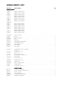
SPARE PARTS LIST

WIRING DIAGRAM
ELECTRICAL
COMPONENT
PART #s
FUSE 3A KE52936-6
FUSE 1.25A KE52936-8
RELAY 1 SK2475500
HEATING ELEMENTS -
SEE "PAN MOUNT ASS EMBLY"
ON/OFF SWITCH SK2474102
HIGH LIMIT KE55069-7
THERMOSTAT SK2142002
SENSOR SK50933-1
HEAT INDICATOR SK50905-1
CIRCUIT BREAKER KE50579-2
TILT LIMIT SWITCH SK2474500
RY10 (RELAY) KE50753-10
RY11 (RELAY) KE50753-10
DC MOTOR KE52832-5
BRIDGE RECTIFIER KE50581
TILT SWITCH KE53137-3
- SECTION KE53184
- CONTACT BLOCK KE53138-1
SENSOR
TILT LIMIT
SWITCH
TILT SWITCH
SK2474103
-
 1
1
-
 2
2
-
 3
3
-
 4
4
-
 5
5
-
 6
6
-
 7
7
-
 8
8
-
 9
9
-
 10
10
-
 11
11
-
 12
12
-
 13
13
-
 14
14
-
 15
15
-
 16
16
-
 17
17
-
 18
18
-
 19
19
-
 20
20


Cleveland PowerPan SEL-30-T1 User manual
- Category
- Electric kettles
- Type
- User manual
- This manual is also suitable for
Ask a question and I''ll find the answer in the document
Finding information in a document is now easier with AI
Related papers
-
 Cleveland SGL-30-T1 User manual
-
 Cleveland SE95051 R5 (Skillets T1 Electric) User manual
-
 Cleveland PowerPan SGL-30-T1 User manual
-
 Cleveland SE95051 R5 (Skillets T1 Electric) User manual
-
 Cleveland PowerPan SGL-30-T1 User manual
-
 Cleveland SEL-30-T1 User manual
-
 Cleveland SE95033 R8 User manual
-
Cleveland KGT-12-T User manual
-
-
Cleveland KET-3-T User manual


Other documents
-
Cleveland Range SGL-30-T1 User manual
-
 BK Resources DDI-2016824 User guide
-
-
-
Crown ECTS-12 Owner's manual
-
all-clad 99009 6.5-Quart User manual
-
-
Kampmann Care Stainless steel products Installation guide
-
FMCG AQUA User manual
-
