Page is loading ...

Operators Manual
ICRFIFrSMFIN°I
Permanently Lubricated
Tank Mounted
AI CO
Model No.
9.167790
• Safety Guidelines
• Assembly
• Operation
= Maintenance
• Service and Adjustments
• Troubleshooting
• Espa_ol
CAUTION; Read the Safety Guidelines
and All Instructions Carefully Before
Operating.
Sears, Roebuck and Co., Hoffman Estates, IL 60179 U.S.A.
Visit our Craftsman website: www.sears.com/craftsman
D24305 Rev. 0 7/20/01

WARRANTY .................................................... 2
SAFETY GUiDELiNES .......................................... 3-6
GLOSSARY .................................................... 7
ACCESSORIES ................................................. 7
ASSEMBLY .................................................... 7
Contents of Carton ............................................ 7
Tools Required for Assembly ..................................... 7
Unpacking .................................................. 8
Assemble Handle ............................................. 8
Assemble Wheels ............................................. 8
Assemble Rubber Feet ......................................... 8
iNSTALLATiON ................................................. 9
Location of Air Compressor ..................................... 9
Grounding Instructions ......................................... 9
Extension Cords .............................................. 9
Voltage and Circuit Protection .................................... 9
OPERATING PROCEDURES ................................... 10-11
Know Your Air Compressor ..................................... 10
Description of Operation ....................................... 10
How to Stop ................................................ 11
Before Starting
Break-in Procedure ....................................... 11
Before Each Start-Up ......................................... 11
How to Start ................................................ 11
MAINTENANCE ............................................. 12-13
Customer Responsibilities ...................................... 12
To Check Safety Valve ........................................ 12
To Drain Tank ............................................... 12
Air Filter- Inspection and Replacement ........................... 12
Air Compressor Pump Intake and Exhaust Valves .................... 13
Motor ..................................................... 13
SERVICE AND ADJUSTMENTS ................................. 14-15
To Replace or Clean Check Valve ................................ 14
To Replace Regulator ......................................... 15
STORAG E .................................................... 15
TROUBLESHOOTING GUIDE ................................... 16-18
ESPAi_OL .................................................. 19-35
HOW TO ORDER REPAIR PARTS ........................... Back Cover
FULL ONE YEAR WARRANTY
AiR COMPRESSOR
If this air compressor fails due to a defect in material or workmanship within one year from the date of
purchase, RETURN IT TO THE NEAREST SEARS REPAIR CENTER THROUGHOUT THE UNITED STATES
AND SEARS WILL REPAIR IT, FREE OF CHARGE. If purchased from Orchard Supply Hardware, return to
the nearest Orchard Store and Orchard will repair it, free of charge.
If this air compressor is used for commercial or rental purposes, the warranty will apply for ninety days
from the date of purchase.
This warranty gives you specific legal rights and you may have other rights which vary from state to state.
Sears, Roebuck and Co., Dept. 817WA, Hoffman Estates, II 60179
D24305 2- ENG

SAFETY and PREVENTING EQUIPMENT PROBLEMS. To help you recognize this information, we use the symbols
below. Please read the manual and pay attention to these sections.
lndicates an imminently hazardous
situation which, if not avoided, will
result in death or serious in)ury.
Indicates a potentially hazardous sit-
uation which, if not avoided, could
result in death or serious in)ury._.
Indicates a potentially hazardous
situation which, if not avoided, m_
result in minor or moderate in)ur_
Used without the safety alert sym-
bol indicates a potentially haz-
ardous situation which, if not avoided, may result in
property dama,cLe_.
O SAVE THESE INSTRUCTIONS _t
IMPROPER OPERATION OR MAINTENANCE OF THIS PRODUCT COULD RESULT IN SERIOUS INJURY
AND PROPERTY DAMAGE. READ AND UNDERSTAND ALL WARNINGS AND OPERATING INSTRUC-
TIONS BEFORE USING THIS EQUIPMENT.
RISK OF EXPLOSION OR FIRE
WHAT CAN HAPPEN
IT IS NORMAL FOR ELECTRICAL CONTACTS WITHIN
THE MOTOR AND PRESSURE SWITCH TO SPARK.
iF ELECTRICAL SPARKS FROM COMPRESSOR COME
INTO CONTACT WITH FLAMMABLE VAPORS, THEY
MAY IGNITE, CAUSING FIRE OR EXPLOSION.
RESTRICTING ANY OF THE COMPRESSOR VENTILA=
TION OPENINGS WILL CAUSE SERIOUS OVERHEATING
AND COULD CAUSE FIRE.
UNATTENDED OPERATION OF THIS PRODUCT COULD
RESULT iN PERSONAL INJURY OR PROPERTY DAM-
AGE. TO REDUCE THE RISK OF FIRE, DO NOT ALLOW
THE COMPRESSOR TO OPERATE UNATTENDED.
HOW TO PREVENT IT
ALWAYS OPERATE THE COMPRESSOR iN A WELL VEN-
TILATED AREA FREE OF COMBUSTIBLE MATERIALS,
GASOLINE OR SOLVENT VAPORS.
IF SPRAYING FLAMMABLE MATERIALS, LOCATE COM-
PRESSOR AT LEAST 20 FEET AWAY FROM SPRAY
AREA. AN ADDITIONAL LENGTH OF HOSE MAY BE
REQUIRED.
STORE FLAMMABLE MATERIALS IN A SECURE LOCA-
TION AWAY FROM COMPRESSOR.
NEVER PLACE OBJECTS AGAINST OR ON TOP OF
COMPRESSOR. OPERATE COMPRESSOR IN AN OPEN
AREA AT LEAST 12 INCHES AWAY FROM ANY WALL
OR OBSTRUCTION THAT WOULD RESTRICT THE FLOW
OF FRESH AIR TO THE VENTiLATiON OPENINGS.
OPERATE COMPRESSOR IN A CLEAN, DRY, WELL VENTI-
LATED AREA. DO NOT OPERATE UNIT INDOORS OR IN
ANY CONFINED AREA.
ALWAYS REMAIN iN ATTENDANCE WITH THE PROD-
UCT WHEN IT IS OPERATING.
ALWAYS DISCONNECT ELECTR(CAL POWER BY MOV=
ING PRESSURE SWITCH LEVER TO THE OFF POSiTiON
AND DRAIN TANK DAILY OR AFTER EACH USE.
3- ENG D24305

RiSK OF BURSTING ._
AIR TANK: THE FOLLOWING CONDiTiONS COULD LEAD TO A WEAKENING OF THE TANK, AND
RESULT iN A VIOLENT TANK EXPLOSION AND COULD CAUSE PROPERTY DAMAGE OR SERIOUS
iNJURY.
WHAT CAN HAPPEN HOW TO PREVENT iT
1. FAILURE TO PROPERLY DRAIN CONDENSED
WATER FROM THE TANK, CAUSING RUST AND
THiNNiNG OF THE STEEL TANK.
2. MODiFiCATiONS OR ATTEMPTED REPAIRS TO THE
TANK.
3. UNAUTHORIZED MODiFiCATiONS TO THE
UNLOADER VALVE, SAFETY VALVE, OR ANY
OTHER COMPONENTS WHICH CONTROL TANK
PRESSURE.
4. EXCESSIVE ViBRATiON CAN WEAKEN THE AiR
TANK AND CAUSE RUPTURE OR EXPLOSION.
ATTACHMENTS & ACCESSORIES:
EXCEEDING THE PRESSURE RATING OF AiR TOOLS,
SPRAY GUNS, AIR OPERATED ACCESSORIES, TIRES AND
OTHER INFLATABLES CAN CAUSE THEM TO EXPLODE
OR FLYAPART, AND COULD RESULT IN SERIOUS INJURY.
DRAIN TANK DAILY OR AFTER EACH USE. iF TANK
DEVELOPS A LEAK, REPLACE IT iMMEDiATELY WiTH A
NEW TANK OR REPLACE THE ENTIRE COMPRESSOR.
NEVER DRILL INTO, WELD, OR MAKE ANY MODIFICA-
TIONS TO THE TANK OR ITS ATTACHMENTS.
THE TANK iS DESIGNED TO WITHSTAND SPECIFIC
OPERATING PRESSURES. NEVER MAKE ADJUST-
MENTS OR PARTS SUBSTiTUTiONS TO ALTER THE
FACTORY SET OPERATING PRESSURES.
FOR ESSENTIAL CONTROL OF AIR PRESSURE,YOU
MUST iNSTALL A PRESSURE REGULATOR AND PRES-
SURE GAUGE TO THE AiR OUTLET (iF NOT EQUIPPED)
OF YOUR COMPRESSOR. FOLLOW THE EQUIPMENT
MANUFACTURERS RECOMMENDATION AND NEVER
EXCEED THE MAXIMUM ALLOWABLE PRESSURE RAT-
ING OF ATTACHMENTS. NEVER USE COMPRESSOR TO
iNFLATE SMALL LOW-PRESSURE OBJECTS SUCH AS
CHILDREN'S TOYS, FOOTBALLS, BASKETBALLS, ETC.
RiSK FROM FLYING OBJECTS
WHAT CAN HAPPEN HOW TO PREVENT iT
THE COMPRESSED AiR STREAM CAN CAUSE SOFT
TISSUE DAMAGE TO EXPOSED SKiN AND CAN PROPEL
DIRT, CHIPS, LOOSE PARTICLES AND SMALL OBJECTS
AT HiGH SPEED, RESULTING IN PROPERTY DAMAGE
OR PERSONAL INJURY.
ALWAYS WEAR ANSi Z87.1 APPROVED SAFETY
GLASSES WiTH SiDE SHIELDS WHEN USING THE
COMPRESSOR.
NEVER POINT ANY NOZZLE OR SPRAYER TOWARD
ANY PART OF THE BODY OR AT OTHER PEOPLE OR
ANIMALS.
ALWAYS TURN THE COMPRESSOR OFF AND BLEED
PRESSURE FROM THE AIR HOSE AND TANK BEFORE
ATTEMPTING MAINTENANCE, ATTACHING TOOLS OR
ACCESSORIES.
D24305 4- ENG

RiSK OF ELECTRICAL SHOCK
WHAT CAN HAPPEN
YOUR AiR COMPRESSOR IS POWERED BY ELECTRICI-
TY. LiKE ANY OTHER ELECTRICALLY POWERED DEVICE,
iF IT IS NOT USED PROPERLY iT MAY CAUSE ELEC-
TRiC SHOCK.
REPAIRS ATTEMPTED BY UNQUALiFiED PERSONNEL
CAN RESULT iN SERIOUS iNJURY OR DEATH BY
ELECTROCUTION.
ELECTRICAL GROUNDING: FAILURE TO PROVIDE ADE-
QUATE GROUNDING TO THIS PRODUCT COULD
RESULT iN SERIOUS iNJURY OR DEATH FROM ELEC-
TROCUTION. SEE GROUNDING iNSTRUCTiONS.
HOW TO PREVENT iT
NEVER OPERATE THE COMPRESSOR OUTDOORS WHEN
iT iS RAINING OR iN WET CONDiTiONS.
NEVER OPERATE COMPRESSOR WITH PROTECTIVE
COVERS REMOVED OR DAMAGED.
ANY ELECTRICAL WiRiNG OR REPAIRS REQUIRED ON
THIS PRODUCT SHOULD BE PERFORMED BY AUTHO-
RIZED SERVICE CENTER PERSONNEL iN ACCOR-
DANCE WITH NATIONAL AND LOCAL ELECTRICAL
CODES.
MAKE CERTAIN THAT THE ELECTRICAL CiRCUiT TO
WHICH THE COMPRESSOR iS CONNECTED PROVIDES
PROPER ELECTRICAL GROUNDING, CORRECT VOLT-
AGE AND ADEQUATE FUSE PROTECTION.
RiSK TO BREATHING
WHAT CAN HAPPEN HOW TO PREVENT iT
THE COMPRESSED AiR DIRECTLY FROM YOUR COM-
PRESSOR iS NOT SAFE FOR BREATHING. THE AiR
STREAM MAY CONTAIN CARBON MONOXIDE, TOXIC
VAPORS, OR SOLID PARTICLES FROM THE TANK.
BREATHING THESE CONTAMINANTS CAN CAUSE
SERIOUS iNJURY OR DEATH.
SPRAYED MATERIALS SUCH AS PAINT, PAINT SOL-
VENTS, PAINT REMOVER, iNSECTiCiDES, WEED
KILLERS, CONTAIN HARMFUL VAPORS AND POISONS.
AiR OBTAINED DIRECTLY FROM THE COMPRESSOR
SHOULD NEVER BE USED TO SUPPLY AiR FOR
HUMAN CONSUMPTION. iN ORDER TO USE AiR PRO-
DUCED BY THiS COMPRESSOR FOR BREATHING, SUIT-
ABLE FILTERS AND IN-LINE SAFETY EQUIPMENT MUST
BE PROPERLY INSTALLED. IN-LINE FILTERS AND
SAFETY EQUIPMENT USED iN CONJUNCTION WiTH
THE COMPRESSOR MUST BE CAPABLE OF TREATING
AIR TO ALL APPLICABLE LOCAL AND FEDERAL
CODES PRIOR TO HUMAN CONSUMPTION.
WORK iN AN AREA WiTH GOOD CROSS-VENTILATION.
READ AND FOLLOW THE SAFETY iNSTRUCTiONS PRO-
VIDED ON THE LABEL OR SAFETY DATA SHEETS FOR
THE MATERIAL YOU ARE SPRAYING. USE A
NIOSH/MSHA APPROVED RESPIRATOR DESIGNED FOR
USE WITH YOUR SPECIFIC APPLICATION.
5- ENG D24305

RiSK OF BURNS
WHAT CAN HAPPEN
TOUCHING EXPOSED METAL SUCH AS THE COMPRES-
SOR HEAD OR OUTLET TUBES, CAN RESULT iN SERi-
OUS BURNS.
HOW TO PREVENT iT
NEVER TOUCH ANY EXPOSED METAL PARTS ON
COMPRESSOR DURING OR IMMEDIATELY AFTER OPER-
ATION. COMPRESSOR WiLL REMAIN HOT FOR SEVER-
AL MINUTES AFTER OPERATION.
DO NOT REACH AROUND PROTECTIVE SHROUDS OR
ATTEMPT MAINTENANCE UNTIL UNiT HAS BEEN
ALLOWED TO COOL.
RiSK FROM MOVING PARTS
WHAT CAN HAPPEN HOW TO PREVENT iT
MOVING PARTS SUCH AS THE PULLEY, FLYWHEEL AND
BELT CAN CAUSE SERIOUS iNJURY IF THEY COME
INTO CONTACT WITH YOU OR YOUR CLOTHING.
ATTEMPTING TO OPERATE COMPRESSOR WiTH DAM-
AGED OR MiSSiNG PARTS OR ATTEMPTING TO REPAIR
COMPRESSOR WiTH PROTECTIVE SHROUDS REMOVED
CAN EXPOSE YOU TO MOVING PARTS AND CAN
RESULT iN SERIOUS iNJURY.
NEVER OPERATE THE COMPRESSOR WiTH GUARDS
OR COVERS WHICH ARE DAMAGED OR REMOVED.
ANY REPAIRS REQUIRED ON THIS PRODUCT SHOULD
BE PERFORMED BY AUTHORIZED SERVICE CENTER
PERSONNEL.
RiSK OF FALLING
WHAT CAN HAPPEN HOW TO PREVENT iT
A PORTABLE COMPRESSOR CAN FALL FROM A TABLE,
WORKBENCH OR ROOF CAUSING DAMAGE TO THE
COMPRESSOR AND COULD RESULT iN SERIOUS
iNJURY OR DEATH TO THE OPERATOR.
ALWAYS OPERATE COMPRESSOR iN A STABLE
SECURE POSiTiON TO PREVENT ACCIDENTAL MOVE-
MENT OF THE UNIT. NEVER OPERATE COMPRESSOR
ON A ROOF OR OTHER ELEVATED POSiTiON. USE
ADDiTiONAL AiR HOSE TO REACH HiGH LOCATIONS.
RiSK OF PROPERTY DAMAGE WHEN TRANSPORTING
COMPRESSOR
(Fire, Inhalation, Damage to Vehicle Surfaces)
For units requiring off in pump or gasoline engines
WHAT CAN HAPPEN HOW TO PREVENT iT
OiL CAN LEAK OR SPILL AND COULD RESULT IN FIRE
OR BREATHING HAZARD, SERIOUS iNJURY OR DEATH
CAN RESULT. OIL LEAKS WILL DAMAGE CARPET, PAINT
OR OTHER SURFACES IN VEHICLES OR TRAILERS.
ALWAYS PLACE COMPRESSOR ON A PROTECTIVE
MAT WHEN TRANSPORTING TO PROTECT AGAINST
DAMAGE TO VEHICLE FROM LEAKS. REMOVE COM-
PRESSOR FROM VEHICLE IMMEDIATELY UPON ARRIVAL
AT YOUR DESTINATION.
D24305 6- ENG

Become familiar with these terms before operating the
unit.
CFM: Cubic feet per minute.
SCFM: Standard cubic feet per minute; a unit of
measure of air delivery.
PSIG: Pounds per square inch gauge; a unit of meas-
ure of pressure.
ASME: American Society of Mechanical Engineers;
made, tested, inspected and registered to meet the
standards of the ASME.
Code Certification: Products that bear one or more
of the following marks: UL, CUL, ETL, CETL, have
been evaluated by OSHA certified independent safety
laboratories and meet the applicable Underwriters
Laboratories Standards for Safety.
Cut-In Pressure: While the motor is off, air tank
pressure drops as you continue to use your accesso-
ry. When the tank pressure drops to the factory set
low pressure the motor will restart automatically. The
low pressure at which the motor automatically restarts
is called "cut-in" pressure.
Cut-Out Pressure: When an air compressor is
turned on and begins to run, air pressure in the air
tank begins to build. It builds to a factory set high
pressure before the motor automatically shuts off -
protecting your air tank from pressure higher than its
capacity. The high pressure at which the motor shuts
off is called "cut-out" pressure.
Branch Circuit: Circuit carrying electricity from elec-
trical panel to outlet.
This unit is capable of powering the following Accessories. The accessories are available through the current
Power and Hand Tool Catalog or full-line Sears stores.
Accessories • Caulk Gun
• In Line Filter • Engine Cleaner
TireAir Chuck • Sand Blaster
Quick Connector Sets Carpentry Tools
(various sizes) • Finishing Nailer/ Stapler
Air PressureRegulators • Construction Nailer/
Oil Fog Lubricators Stapler
Air Hose: Socket Driving
1/4", 3/8" or 1/2" I.D. • 1" impact Wrench
in various lengths • 3/4" Impact Wrench
Specialty Tools • 1/2" Impact Wrench
Inflating/Blow Gun • 3/8" Impact/Butterfly
Grease Gun Wrench
1/2" Ratchet • Reciprocating Saw
3/8" Ratchet • Nibbler
1/4" Ratchet Spray Painting
Material Shaping • Multi-Purpose Spray
2.625" Hammer Gun
1.625" Hammer • Automotive Spray Gun
1/2" Drill • HVLP Spray Gun
,, 3/8" Drill Finishing/Sanding
High Speed Rotary • High Speed Sander
Mini High Speed Rotary • Random Orbit Sander
Cut-Off Tool • 6" DASander
Shear • Jitterbug Sander
4" Angle Grinder • Straight Line Sander
Contents of Carton
1 - Air Compressor
1- Handle
4 - Self Tapping Screws
2- Wheels
2 - Shoulder Bolts, 3/8-16
2 - Hex Nuts, 3/8-16
2 - 1/4-20 Hex Nuts
2 - Flat Washers
2 - Rubber Bumpers
2- Screws, 1/4-20 x .75
Tools Required for Assembly
1 - 9/16" socket or open end wrench
1 - 3/8" socket or open end wrench
1 - 1/4" socket or open end wrench
7- ENG D24305

Unpacking
1. Remove unit from carton and discard all packag-
ing. NOTE: Save all parts bags.
Assemble Handle
1. Insert the handle inside the compressor saddle
and line up the two bolt holes on each side.
2. Install the four screws, two on each side.
3. Tighten securely.
Screw
Assemble Wheels
.
it will be necessary to brace
or support one side of the
outfit when installing the wheels because the
compressor will have a tendency to tip.
Attach wheels with shoulder bolts and nuts as
shown.
2. Tighten securely. NOTE: The outfit will sit level if
the wheels are properly installed.
I___ The wheels and handle
do not provide adequate
clearance, stability or support for pulling
the unit up and down stairs or steps. The
unit must be lifted, or pushed up a ramp.
Assemble Rubber Feet
1. Attach rubber feet with the screws, washers and
nuts provided as shown in previous figure.
2. Tighten securely.
'_ Flat Washer
i_-_ Rubber Foot
Screw
Shoulder
Bolt
D24305 8- ENG

HOW TO SET UP YOUR UNiT iMPROPERGROUNDING
CAN RESULT iN ELEC=
Location of the Air Compressor TRICAL SHOCK.
Locate the air compressor in a clean, dry and well
ventilated area. The air compressor should be located
at least 12" away from the wall or other obstructions
that will interfere with the flow of air. The air compres-
sor pump and shroud are designed to allow for proper
cooling. The ventilation openings on the compressor
are necessary to maintain proper operating tempera-
ture. Do not place rags or other containers on or near
these openings.The air filter must be kept clear of
obstructions which could reduce air flow to the air
compressor.
GROUNDING iNSTRUCTiONS
RISK OF ELECTRICAL
SHOCK. In the event of a
short circuit, grounding reduces the risk of
shock by providing an escape wire for the
electric current. This air compressor must be
properly grounded.
The portable air compressor is equipped with a cord
having a grounding wire with an appropriate ground-
ing plug (see following illustrations). The plug must be
used with an outlet that has been installed and
grounded in accordance with all local codes and ordi-
nances.
1. The cord set and plug with this unit contains a
grounding pin. This plug MUST be used with a
grounded outlet.
iMPORTANT: The outlet being used must be installed
and grounded in accordance with all local codes and
ordinances.
2. Make sure the outlet being used has the same
configuration as the grounded plug. DO NOT USE
AN ADAPTER. See illustration.
Grounding Pin
_Grounded
J Outlets
.
.
Inspect the plug and cord before each use. Do
not use if there are signs of damage.
If these grounding instructions are not completely
understood, or if in doubt as to whether the com-
pressor is properly grounded, have the installation
checked by a qualified electrician.
Do not modify the plug provided, if it does
not fit the available outlet, a correct outlet
should be installed by a qualified electri-
cian.
Repairs to the cord set or plug MUST be
made by a qualified electrician.
Extension Cords
Use extra air hose instead of an extension cord to
avoid voltage drop and power loss to the motor, and
to prevent overheating.
If an extension cord must be used, be sure it is:
• a 3-wire extension cord that has a 3-blade
grounding plug, and a 3-slot receptacle that will
accept the plug on the product
• in good condition
no longer than 50 feet
12 gauge (AWG) or larger. (Wire size increases as
gauge number decreases. 10 AWG and 8 AWG
may also be used. DO NOT USE 14 OR 16
AWG.)
Voltage and Circuit Protection
Refer to the Parts Manual for the voltage and mini-
mum branch circuit requirements.
Certain air compressors can be operated on a 15 amp
circuit if the following conditions are met.
1. Voltage supply through branch circuit is 15 amps.
2. Circuit is not used to supply any other electrical
needs (lights, appliances, etc.).
3. Extension cords comply with specifications.
4. Circuit isequipped with a 15 amp circuit breaker
or 15 amp time delay fuse. NOTE: If compressor
is connected to a circuit protected by fuses, use
only time delay fuses. Time delay fuses should be
marked "D" in Canada and "T" in the US.
If any of the above conditions cannot be met, or if
operation of the compressor repeatedly causes inter-
ruption of the power, it may be necessary to operate it
from a 20 amp circuit. It is not necessary to change
the cord set.
9- ENG D24305

Know Your Air Compressor
READ THIS OWNER'S MANUAL AND SAFETY RULES BEFORE OPERATING YOUR UNIT. Compare the illustra-
tions with your unit to familiarize yourself with the location of various controls and adjustments. Save this manual
for future reference.
Description of Operation
Become familiar with these controls before operating
the unit.
On/Auto/Off Switch: Turn this switch ON to provide
automatic power to the pressure switch and OFF to
remove power at the end of each use.
Pressure Switch: The pressure switch automatically
starts the motor when the air tank pressure drops
below the factory set "cut-in" pressure. It stops the
motor when the air tank pressure reaches the factory
set "cut-out" pressure.
Safety Valve: If the pressure switch does not shut off
the air compressor at its "cut-out" pressure setting,
the safety valve will protect against high pressure by
"popping out" at its factory set pressure (slightly high-
er than the pressure switch "cut-out" setting).
Outlet Pressure Gauge: The outlet pressure gauge
indicates the air pressure available at the outlet side
of the regulator. This pressure is controlled by the reg-
ulator and is always less than or equal to the tank
pressure.
Tank Pressure Gauge: The tank pressure gauge
indicates the reserve air pressure in the tank.
Regulator: Controls the air pressure shown on the
outlet pressure gauge. Pull the knob out and turn
clockwise to increase pressure and counterclockwise
to decrease pressure. When the desired pressure is
reached push knob in to lock in place.
Drain Valve: The drain
valve is located at the
base of the air tank and is
used to drain condensa-
tion at the end of each
use.
Cooling System (not shown}: This compressor con-
tains an advanced design cooling system. At the heart
of this cooling system is an engineered fan. It is per-
fectly normal for this fan to blow air through the vent
holes in large amounts. You know that the cooling
system is working when air is being expelled.
Air Compressor Pump {not shown}: Compresses air
into the air tank. Working air is not available until the
compressor has raised the air tank pressure above
that required at the air outlet.
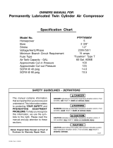
Check Valve: When
the air compressor is
operating, the check
valve is "open", allow-
ing compressed air to
enter the air tank.
When the air com-
pressor reaches "cut-
out" pressure, the
check valve "closes",
allowing air pressure
to remain inside the
air tank.
Pressure Release Valve: The pressure release valve,
located on the side of the pressure switch, is
designed to automatically release compressed air
from the compressor head and the outlet tube when
the air compressor reaches "cut-out" pressure or is
shut off. The pressure release valve allows the motor
to restart freely. When the motor stops running, air will
be heard escaping from this valve for a few seconds.
No air should be heard leaking when the motor is run-
ning, or continuous leaking after unit reaches "cut-
out" pressure.
Air Intake Filter {not shown} This filter is designed
to clean air coming into the pump. This filter must
always be clean and ventilation openings free from
obstructions. See "Maintenance".
D24305 10 - ENG

How to Use Your Unit
How to Stop:
1. Set the On/Auto/Off lever to "OFF".
Before Starting
Break-in Procedure
_ Serious damage may result if the
following break-in instructions are
not closely followed.
This procedure is required before the air compressor
is put into service and when the check valve or a
complete compressor pump has been replaced.
1. Make sure the On/Auto/Off lever is in the "OFF"
position.
NOTE: If quick connect is installed, pull coupler back
until it clicks to prevent air from escaping through the
quick connect.
.
.
Plug the power cord into the correct branch circuit
receptacle. (Refer to Voltage and Circuit
Protection paragraph in the Installation section of
this manual.)
Open the drain valve
fully (counter-clock-
wise) to permit air to
escape and prevent air Valve
pressure build up in
the air tank during the
break-in period.
4. Move the On/Auto/Off lever to "ON/AUTO" posi-
tion. The compressor will start.
5. Run the compressor for 15 minutes. Make sure
the drain valve is open and there is minimal air
pressure build-up in tank.
6. After 15 minutes, close the drain valve (clock-
wise). The air receiver will fill to "cut-out" pressure
and the motor will stop.
The compressor is now ready for use.
Before Each Start=Up:
1. Place On/Auto/Off lever to "OFF".
.
.
Pull regulator knob out, turn counter-clockwise
until it stops. Push knob in to lock in place.
Attach hose and accessories. NOTE: The hose or
accessory will require a quick connect plug if the
air outlet is equipped with a quick connect.
Too much air pressure
causes a hazardous risk of
bursting. Check the manufacturer's maximum
pressure rating for air tools and accessories.
The regulator outlet pressure must never
exceed the maximum pressure rating.
How to Start:
1. Turn the On/Auto/Off lever to "AUTO" and allow
tank pressure to build. Motor will stop when tank
pressure reaches "cut-out" pressure.
2. Pull the regulator knob out and turn clockwise to
increase pressure. When the desired pressure is
reached push knob in to lock in place. The com-
pressor is ready for use.
NOTE: Always operate the air compressor in well-
ventilated areas free of gasoline or other combustible
vapors. If the compressor is being used to operate a
sprayer DO NOT place near the spray area.
11 - ENG D24305

Customer Responsibilities
Before Daily or
after Frequently Yearly
each use
each use
Check Safety Valve ®
Drain Tank ®
Air Filter ®
Air compressor pump intake and exhaust valves ®
Unit cycles automatically when power is on. When performing maintenance, you may
be exposed to voltage sources, compressed air, or moving parts. Personal injuries
can occur. Before performing any maintenance or repair, disconnect power source from the compressor
and bleed off all air pressure.
To ensure efficient operation and longer life of the air compressor outfit, a routine maintenance schedule should
be prepared and followed. The following routine maintenance schedule is geared to an outfit in a normal working
environment operating on a daily basis. If necessary, the schedule should be modified to suit the conditions
under which your compressor is used. The modifications will depend upon the hours of operation and the work-
ing environment. Compressor outfits in an extremely dirty and/or hostile environment will require a greater fre-
quency of all maintenance checks.
NOTE: See "Operation" section for the location of controls.
To Check Safety Valve
lf the safety valve does
not work properly, over-
pressurization may occur, causing air tank
rupture or an explosion. Before starting com-
pressor, pull the ring on the safety valve to
make sure that the safety valve operates
freely. If the valve is stuck or does not operate
smoothly, it must be replaced with the same
type of valve.
To Drain Tank
.
2.
.
4.
.
Set the On/Auto/Off lever to "OFF".
Pull the regulator knob out and turn clockwise to
set the outlet pressure to zero.
Remove the air tool or accessory.
Pull ring on safety valve allowing air to bleed from
the tank until tank pressure is approximately 20
psi. Release safety valve ring.
Drain water from air tank by opening drain valve
(counter-clockwise) on bottom of tank.
Water will condense in
the air tank. If not
drained, water will corrode and weaken the air
tank causing a risk of air tank rupture.
6. After the water has been drained, close the drain
valve (clockwise). The air compressor can now
be stored.
NOTE: If drain valve is plugged, release all air pressure.
The valve can then be removed, cleaned, and rein-
stal led.
Air Filter = Inspection and Replacement
Hot surfaces. Risk of
burn. Compressor heads
are exposed when filter cover is removed.
Allow compressor to cool prior to servicing.
A dirty air filter will not allow the compressor to oper-
ate at full capacity. Keep the air filter clean at all
times.
1. Remove the air filter cover.
2. Remove the air filter and make sure it is clean.
IMPORTANT: Do not operate the compressor with
the air filter removed.
D24305 12 - ENG

3. If dirty, rinse air filter with warm water and
squeeze dry.
4. Replace air filter and air filter cover.
NOTE: If the air filter is extremely dirty it will need to
be replaced. Refer to the "Repair Parts" for the cor-
rect part number.
Air Compressor Pump Intake and Exhaust
Valves
Once a year have a Trained Service Technician check
the air compressor pump intake and exhaust valves.
Motor
The motor has an automatic reset thermal overload
protector. If the motor overheats for any reason, the
overload protector will shut off the motor. The motor
must be allowed to cool down before restarting. The
compressor will automatically restart after the motor
cools.
If the overload protector shuts the motor off frequent-
ly, check for a possible voltage problem. Low voltage
can also be suspected when:
1. The motor does not get up to full power or speed.
2. Fuses blow out when starting the motor; lights
dim and remain dim when motor is started and is
running.
13 - ENG D24305

Unit cycles automatically when power is on. When doing Maintenance, you may be exposed
to voltage sources, compressed air or moving parts. Personal injuries can occur. Before per-
forming any Maintenance or repair, unplug the compressor and bleed off all air pressure.
ALL MAINTENANCE AND REPAIR OPERATIONS NOT LISTED MUST BE PERFORMED BY
TRAINED SERVICE TECHNiCiAN.
Before servicing:
o Unplug or disconnect electrical supply to the
air compressor.
Bleed tank of pressure.
Allow the air compressor to cool.
To Replace or Clean Check Valve
1. Release all air pressure from air tank. See "To
Drain Tank" in the Maintenance section.
2. Unplug outfit.
3. Remove the regulator ring and remove the con-
sole cover.
4. Using a phillips screwdriver remove the air filter
cover.
7. Using an adjustable wrench loosen pressure relief
tube nut at air tank and pressure switch. Carefully
move pressure relief tube away from check valve.
.
.
Unscrew the check valve (turn counterclockwise)
using a 7/8" open end wrench. Note the orienta-
tion for reassembly.
Using a screwdriver, carefully push the valve disc
up and down. NOTE: The valve disc should move
freely up and down on a spring which holds the
valve disc in the closed position, if not the check
valve needs to be cleaned or replaced.
Screwdriver
in closed position
disc is visible.
in open position
nothing is visible.
5. Remove the rear shrouds using -i--20 torx wrench.
.
Using an adjustable wrench loosen outlet tube nut
at air tank and pump. Carefully move outlet tube
up away from check valve.
10. Clean or replace the check valve. A solvent, such
as paint or varnish remover can be used to clean
the check valve.
11. Apply sealant to the check valve threads. Reinstall
the check valve (turn clockwise).
12. Replace the pressure release tube. Tighten nuts.
13. Replace the outlet tube and tighten nuts.
14. Replace shrouds and console.
15. Perform the Break-in Procedure. See "Break-in
Procedure" in the Operation section.
D24305 14 - ENG

To Replace Regulator
1. Release all air pressure from air tank. See "To
Drain Tank" in the Maintenance section.
2. Unplug outfit.
3. Remove the regulator ring and remove the con-
sole cover.
4. Using an adjustable wrench loosen pressure relief
tube nut at air tank and pressure switch.
5. Using an adjustable wrench, rotate the pressure
switch assembly as shown.
6. Remove the outlet pressure gauge, tank pressure
gauge, and quick connect (if equipped) from the
regulator.
7. Remove the regulator.
8. Apply pipe sealant tape to the nipple.
9. Assemble the regulator and orient as shown.
NOTE: Arrow indicates flow
of air. Make sure it is point-
ing in the direction of air
flow.
10. Reapply pipe sealant to
outlet pressure gauge,
tank pressure gauge,
and quick connect.
11. Reassemble outlet pressure gauge,tank pressure
gauge, and quick connect. Orient outlet pressure
gauge and tank pressure gauge to read correctly.
Tighten quick connect with wrench.
12. Rotate pressure switch assemble into correct
position.
13. Replace console cover and regulator ring.
Connect
Before you store the air compressor, make sure you
do the following:
1. Review the "Maintenance" section on the preced-
ing pages and perform scheduled maintenance as
necessary.
2. Set the On/Auto/Off lever to "OFF".
3. Turn the regulator counterclockwise and set the
outlet pressure to zero.
4. Remove the air tool or accessory.
5. Pull ring on safety valve allowing air to bleed from
the tank until tank pressure is approximately 20
psi. Release safety valve ring.
6. Drain water from air tank by opening drain valve
on bottom of tank.
.
_ ater will condense in the
air tank. If not drained,
water will corrode and weaken the air tank
causing a risk of air tank rupture.
After the water has been drained, close the drain
or drain valve.
NOTE: If drain valve is plugged, release all air pres-
sure. The valve can then be removed, cleaned, then
reinstalled.
8. Protect the electrical cord and air hose from dam-
age (such as being stepped on or run over). Wind
them loosely around the compressor handle. (if so
equipped)
Store the air compressor in a clean and dry location.
15 - ENG D24305

Performing repairs may expose voltage sources, moving parts or compressed air sources,
moving parts or compressed air sources. Personal injury may occur. Prior to attempting any
repairs, unplug the air compressor and bleed off all air tank air pressure.
PROBLEM
Excessive tank pressure - safety
valve pops off.
CAUSE
Pressure switch does not shut off
motor when compressor reaches
"cut-out" pressure.
Air leaks at fittings.
Air leaks at or inside check valve
Air leaks at pressure switch
release valve.
Air leaks in air tank or at air tank
welds.
Air leaks between head and valve
plate.
Pressure reading on the regulated
pressure gauge drops when an
accessory is used.
Pressure switch "cut-out" too
high.
Tube fittings are not tight enough.
Check valve seat damaged.
Defective pressure switch release
valve.
Defective air tank.
Leaking seal.
It is normal for "some" pressure
drop to occur.
CORRECTION
Move On/Auto/Off lever to the
"OFF" position, if the outfit does
not shut off contact a Trained
Service Technician.
Contact a Trained Service
Technician.
Tighten fittings where air can be
heard escaping. Check fittings
with soapy water solution. DO
NOT OVERTIGHTEN.
A defective check valve results in
a constant air leak at the pressure
release valve when there is pres-
sure in the tank and the compres-
sor is shut off. Replace check
valve. Refer the "To Replace or
Clean Check Valve" in the
"Service and Adjustment" section.
Contact a Trained Service
Technician.
Air tank must be replaced. Do not
repair the leak.
Do not drill into, weld or otherwise
modify air tank or it will weaken.
The tank can rupture or explode.
Contact a Trained Service
Technician.
If there is an excessive amount of
pressure drop when the accessory
is used, adjust the regulator fol-
lowing the instructions in the
"Description of Operation" para-
graph in the "Operation Section.
NOTE: Adjust the regulated pres-
sure under flow conditions (while
accessory is being used).
D24305 16 - ENG

PROBLEM
Knocking Noise.
CAUSE
Possible defect in safety valve.
Compressor is not supplying
enough air to operate accessories.
Regulator knob has continuous air
leak.
Regulator will not shut off air out-
let.
Defective check valve.
Prolonged excessive use of air.
Compressor is not large enough
for air requirement.
Hole in hose.
Check valve restricted.
Air leaks.
Restricted air intake filter
Damaged regulator
Damaged regulator
CORRECTION
Operate safety valve manually by
pulling on ring. If valve still leaks,
it should be replaced.
Remove and clean, or replace.
Decrease amount of air usage.
Check the accessory air require-
ment. If it is higher than the
SCFM or pressure supplied by
your air compressor, you need a
larger compressor.
Check and replace if required.
Remove and clean, or replace.
Tighten fittings.
Clean or replace air intake filter.
Do not operate the air compressor
with the filter removed. Refer to
the "Air Filter" paragraph in the
"Maintenance " section.
Replace
Replace
17 - ENG D24305

PROBLEM
Motor will not run.
CAUSE
Motor overload protection switch
has tripped
Tank pressure exceeds pressure
switch "cut-in" pressure.
Extension cord is wrong length or
gauge.
Check valve stuck open.
Loose electrical connections.
Possible defective motor or start-
ing capacitor.
Paint spray on internal motor
parts.
Pressure release valve on pres-
sure switch has not unloaded
head pressure.
Fuse blown, circuit breaker
tripped.
CORRECTION
Let motor cool off and overload
switch will automatically reset.
Motor will start automatically
when tank pressure drops below
"cut-in" pressure of pressure
switch.
Check for proper gauge wire and
cord length.
Remove and clean, or replace.
Check wiring connection inside
pressure switch and terminal box
area.
Have checked by a Trained
Service Technician.
Have checked by a Trained
Service Technician. Do not oper-
ate the compressor in the paint
spray area. See flammable vapor
warning.
Bleed the line by pushing the lever
on the pressure switch to the "off"
position; if the valve does not
open, replace switch.
. Check fuse box for blown fuse
and replace as necessary.
Reset circuit breaker. Do not
use a fuse or circuit breaker
with higher rating than that
specified for your particular
branch circuit.
2. Check for proper fuse. You
should use a time delay fuse.
3. Check for low voltage condi-
tions and/or proper extension
cord.
. Disconnect the other electrical
appliances from circuit or
operate the compressor on its
own branch circuit.
D24305 18 - ENG

GARANT_ ................................................. 19
NORMAS DE SEGURIDAD .................................. 20-23
GLOSARIO ................................................. 24
ACCESORIOS .............................................. 24
ENSAMBLADO ........................................... 24-25
Contenido de la caja ....................................... 24
Herramientas requeridas para el ensamblado .................... 24
Desempaque ............................................. 25
Ensamblado de la mango ................................... 25
Ensamble de las ruedas .................................... 25
Ensamble de las patas de caucho ............................. 25
INSTALACION .............................................. 26
Ubicaci6n del compresor de aire .............................. 26
Instrucciones para conectar a tierra ........................... 26
Extensiones electricas ...................................... 26
Protecci6n del voltaje y del circuito ............................ 26
PROCEDIMIENTOS OPERATIVOS ............................ 27-28
Conozca su compresor de aire ............................... 27
Descripci6n de operaciones ................................. 27
Como usar su unidad ...................................... 28
Como detenerla ........................................... 28
Antes de poner en marcha ............................................. 28
Procedimiento para el asentamiento ...................................... 28
Antes de cada puesta en marcha ............................. 28
C6mo ponder en marcha ................................... 28
MANTENIMIENTO ......................................... 29-30
Responsabilidades del cliente ................................ 29
Como verificar la valvula de seguridad ......................... 29
Como drenar el tanque ..................................... 29
Filtro de Aire - Inspecci6n y reemplazo ......................... 29
Valvulas de entrada y escape de la bomba del compressor de aire .... 30
Motor .................................................. 30
SERVIClO Y AJUSTES ..................................... 31-32
Para reemnplazar o limpiar la valvula reguladoa ................... 31
Para reemplazar el regulador ................................. 32
ALMACENAJE .............................................. 32
GU|A DE DIAGN()STICO DE PROBLEMAS ..................... 33-35
COMO SOLICITAR PIEZAS PARA REPARACION ............ contratapa
GARANTiA COMPLETA POR UN Ai_O
COMPRESOR DE AIRE
Si este compresor de aire fallara por defectos en materiales o mano de obra dentro del lapso de un aho a partir de la fecha
de su compra, DEVUC:LVALOAL CENTRO DE REPARACIONES SEARS MAS CERCANO DENTRO DE LOS ESTADOS
UNIDOS, Y SEARS LO REPARARA, LIBRE DE CARGO. Si se hubiese comprado a Orchard Supply Hardware, devuelvalo al
comercio Orchard mb,s cercano y Orchard Io reparar& libre de cargo.
Si este compresor de aire fuese utilizado para prop6sitos comerciales o de alquiler, la garanfia solo tendrb, validez por
noventa dfas a partir de la compra.
Esta garantfa le otorga derechos legales especfficos, aunque usted podrb, tener otros derechos que podrfan variar entre
estados.
Sears, Roebuck and Co., Dept. 817WA, Hoffman Estates, II 60179
19 - SP D24305

SEGURIDADY PREVENCION DE PROBLEMAS DEL EQUIPO: Para ayudar al reconocimiento de esta informaci6n, hemos
utilizado los simbolos mostrados abajo. Sirvase leer el manual y prestar atenci6n a dichas secciones.
_ ndica una situaci6n de inminente riesgo, la cual,
si no es evitada, causarA la muerte o lesiones
serias.
_ ndica una situaci6n potencialmente
riesgosa, que si no es evitada, podria
resultar en la muerte o lesiones serias.
lndica una situaci6n potencialmente
peligrosa, la cual, si no es evitada, podria
resultar en lesiones menores o moderadas.
_ sado sin el simbolo de seguridad de
alerta indica una situaci6n potencial-
mente riesgosa la que, si no es evitada, podria causar da_os en
la propiedad.
O GUARDE ESTAS INSTRUCCIONES _Q
La operaci6n o el mantenimiento inadecuados de este producto podrian ocasionar serias lesiones y
dahos a la propiedad. Lea y comprenda todas las advertencias e instrucciones de funcionamiento
antes de utilizar este equipo.
RIESGO DE EXPLOSION O INCENDIO
&QUI_ PUEDE OCURRIR?
PARA LOS CONTACTOS ELECTRICOS ES NORMAL LA
EXlSTENCiA DE CNISPAS ENTRE EL MOTOR Y EL
INTERRUPTOR A PRESION.
SI LAS CHISPAS ELI_CTRICAS PROVENIENTES DEL COMPRESOR
TOMARAN CONTACTO CON EMANACIONES DE MATERIALES
INFLAMABLES, ELLOS PODRJAN ARDER ORIGINANDO
INCENDIO O EXPLOSION.
RESTRINGIR CUALQUIERA DE LAS ABERTURAS DE
VENTILACION CAUSARA UN SERIO RECALENTAMIENTO
Y PODRJA PRODUCIR UN INCENDIO.
DEJAR DESATENDIDO ESTE PRODUCTO MIENTRAS EL
MISMO ESTA EN FUNCIONAMIENTO PUEDE RESULTAR EN
LESIONES PERSONALES O DAI_OS A LA PROPIEDAD. PARA
REDUCIR EL RIESGO DE INCENDIO, NO PERMITA QUE EL
COMPRESOR OPERE DESATENDIDO.
&COMO PREVENIRLO?
OPERE SiEMPRE EL COMPRESOR EN UN SECTOR BIEN
VENTILADO Y LiBRE DE MATERiALES COMBUSTIBLES,
GASOLINA O EMANACIONES DE SOLVENTE.
EN UN AREA DE ROCIADO DE MATERIALES INFLAMABLES,
UBIQUE AL COMPRESOR POR LO MENOS A 6,1M (20 PIES} BE
DISTANClA DEL AREA DE ROClADO. PODRJA REQUERIRSE
UNA EXTENSION DE LA MANGUERA.
ALMACENE LOS MATERiALES INFLAMABLES EN UNA
UBICACION SEGURA, ALEJADOS DEL COMPRESOR.
JAMAS COLOQUE OBJETOS APOYADOS O SOBRE EL COM-
PRESOR. OPERE EL COMPRESOR EN UN SECTOR ABIERTO,
POR LO MENOS A 30 CM (12 PULGADAS} ALEJADO DE
CUALQUIER PARED U OBSTRUCCION QUE RESTRINJA EL
FLUJO DE AIRE FRESCO A LAS ABERTURAS DE VENTILACION.
OPERE EL COMPRESOR EN UN SECTOR LIMPIO, SECO, Y BIEN
VENTILADO. NO OPERE LA UNIDAD EN ESPACIOS CERRADOS
O CUALQUIER AREA CONFINADA.
MANTF:NGASE SIEMPRE ALERTA CADA VEZ QUE EL
PRODUCTO ESTE FUNCIONANDO.
DESCONECTE SIEMPRE EL SUMiNISTRO ELECTRICO
MOVIENDO LA PALANCA CONMUTADORA DE PRESION
A LA POSICION DE APAGADO (OFF}
D24305 20- SP
/