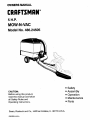
Craftsman 48624505 Owner's manual
- Category
- Lawnmowers
- Type
- Owner's manual
This manual is also suitable for
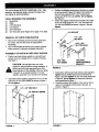
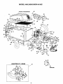
Craftsman 48624505 is a powerful 5 H.P. MOW-N-VAC that was designed to help you to keep your lawn clean and tidy. It is equipped with a variety of features that make it easy to use, including a remote hose kit, a vinyl hard top boot, and a top cover. The MOW-N-VAC also has a large capacity cart that can hold up to 10 bushels of debris, making it ideal for large lawns.
Craftsman 48624505 is a powerful 5 H.P. MOW-N-VAC that was designed to help you to keep your lawn clean and tidy. It is equipped with a variety of features that make it easy to use, including a remote hose kit, a vinyl hard top boot, and a top cover. The MOW-N-VAC also has a large capacity cart that can hold up to 10 bushels of debris, making it ideal for large lawns.


-
 1
1
-
 2
2
-
 3
3
-
 4
4
-
 5
5
-
 6
6
-
 7
7
-
 8
8
-
 9
9
-
 10
10
-
 11
11
-
 12
12
-
 13
13
-
 14
14
-
 15
15
-
 16
16
-
 17
17
-
 18
18
-
 19
19
-
 20
20
-
 21
21
-
 22
22
-
 23
23
-
 24
24
-
 25
25
-
 26
26
-
 27
27
-
 28
28


Craftsman 48624505 Owner's manual
- Category
- Lawnmowers
- Type
- Owner's manual
- This manual is also suitable for
Craftsman 48624505 is a powerful 5 H.P. MOW-N-VAC that was designed to help you to keep your lawn clean and tidy. It is equipped with a variety of features that make it easy to use, including a remote hose kit, a vinyl hard top boot, and a top cover. The MOW-N-VAC also has a large capacity cart that can hold up to 10 bushels of debris, making it ideal for large lawns.
Ask a question and I''ll find the answer in the document
Finding information in a document is now easier with AI
Related papers
-
Craftsman 48624515 User manual
-
-
-
-
-
-
-
-
-
Other documents
-
Agri-Fab 551889A User manual
-
-
-
-
MTD 45-01763 User manual
-
Agri-Fab 45-0240 User manual
-
-
-
-