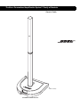
Bose Personalized Amplification System Operating instructions
- Category
- Audio amplifiers
- Type
- Operating instructions

The Bose
®
Personalized Amplification System™ Family of Products
Owner’s Guide
www.bose.com/musicians
70
“A Mark of Quality”

2
Svenska Nederlands Italiano Français Español Deutsch Dansk EnglishDanskDeutschItalianoNederlandsSvenska Français Español English
Safety Information
Please read this owner’s guide
Please take the time to follow the instructions in this owner’s guide carefully. It will help you set up and operate
your system properly and enjoy all of its advanced features. Please save this owner’s guide for future reference.
WARNING:
To reduce the risk of fire or electrical shock, do not expose the system to rain or moisture.
WARNING:
To prevent electric shock, match the wide blade of the line cord plug to the wide slot of the AC (mains)
receptacle.
CAUTION
CAUTION
RISK OF ELECTRICAL SHOCK
DO NOT OPEN
CAUTION: TO REDUCE THE RISK OF ELECTRIC SHOCK,
DO NOT REMOVE COVER (OR BACK).
NO USER-SERVICABLE PARTS INSIDE.
REFER SERVICING TO QUALIFIED PERSONNEL.
WARNING: To reduce the risk of electric shock, do not disassemble this system unless you are qualified.
Refer servicing to qualified service personnel.
These CAUTION marks may be located on the enclosures of the Personalized Amplification System™ PS1
power stand:
The lightning flash with arrowhead symbol within an equilateral triangle alerts the user to the presence of
uninsulated dangerous voltage within the system enclosure that may be of sufficient magnitude to consti-
tute a risk of electrical shock.
The exclamation point within an equilateral triangle, as marked on the system, is intended to alert the user
to the presence of important operating and maintenance instructions in this owner’s guide.
CAUTION:
No naked flame sources, such as lighted candles, should be placed on the apparatus.
CAUTION:
Where the mains plug is used as the disconnect device, such disconnect device shall remain readily
operable.
©2005 Bose Corporation. No part of this work may be reproduced, modified, distributed or otherwise used without prior written
permission.

Important Safety Instructions
English Deutsch FrançaisDansk Español Italiano SvenskaNederlandsDansk Italiano SvenskaDeutsch NederlandsEnglish FrançaisEspañol
1. Read these instructions.
2. Keep these instructions.
3. Heed all warnings.
4. Follow all instructions.
5. Do not use this apparatus near water.
6. Clean only with a dry cloth.
7. Do not block any ventilation openings. Install in
accordance with the manufacturer’s instruc-
tions.
8. Do not install near any heat sources, such as
radiators, heat registers, stoves or other appa-
ratus (including amplifiers) that produce heat.
9. Do not defeat the safety purpose of the polar-
ized or grounding-type plug. A polarized plug
has two blades with one wider than the other. A
grounding-type plug has two blades and a third
grounding prong. The wider blade or third prong
is provided for your safety. If the provided plug
does not fit into your outlet, consult an electri
-
cian for replacement of the obsolete outlet.
10. Protect the power cord from being walked on or
pinched, particularly at plugs, convenience
receptacles, and the point where they exit from
the apparatus.
11. Only use attachments/accessories specified by
the manufacturer.
12. Use only with the cart, stand, tripod,
bracket or table specified by the man-
ufacturer or sold with the apparatus.
When a cart is used, use caution when
moving the cart/apparatus combination to avoid
injury from tip-over.
13. Unplug this apparatus during lightning storms
or when unused for long periods of time.
Information about products that
generate electrical noise
This equipment has been tested and found to
comply with the limits for a Class A digital device,
pursuant to Part 15 of the FCC rules. These limits
are designed to provide reasonable protection
against harmful interference in a commercial envi-
ronment. This equipment generates, uses, and can
radiate radio frequency energy and, if not installed
and used in accordance with the instructions, may
cause harmful interference to radio communications.
Operation of this equipment in a residential area is
likely to cause harmful interference in which case the
user will be required to correct the interference at his
own expense.
This product complies with the Canadian ICES-003
Class A specifications.
14.
Refer all servicing to qualified service personnel.
Servicing is required when the apparatus has
been damaged in any way, such as power-supply
cord or plug is damaged, liquid has been spilled
or objects have fallen into the apparatus, the
apparatus has been exposed to rain or moisture,
does not operate normally, or has been dropped.
15. To prevent risk of fire or electric shock, avoid
overloading wall outlets, extension cords, or
integral convenience receptacles.
16. Do not let objects or liquids enter the product –
as they may touch dangerous voltage points or short-
circuit parts that could result in a fire or electric shock.
17. See product enclosure bottom for safety related
markings.
18. Use proper power sources – Plug the product into
a proper power source, as described in the operating
instructions or as marked on the product.
19. Apparatus shall not be exposed to dripping or
splashing, and no objects filled with liquids,
such as vases, shall be placed on the apparatus.
3
Page is loading ...
Page is loading ...

6
Contents
Setup . . . . . . . . . . . . . . . . . . . . . . . . . . . . . . . . . . . . . . . . . . . . . . . . . . . . . . . . . . . . . . . . . . . . . . . . 7
Before you begin . . . . . . . . . . . . . . . . . . . . . . . . . . . . . . . . . . . . . . . . . . . . . . . . . . . . . . . . . . . 7
Unpacking . . . . . . . . . . . . . . . . . . . . . . . . . . . . . . . . . . . . . . . . . . . . . . . . . . . . . . . . . . . . . . . . 8
Placing the product in the right location for your performance . . . . . . . . . . . . . . . . . . . . . . . . 9
Product assembly . . . . . . . . . . . . . . . . . . . . . . . . . . . . . . . . . . . . . . . . . . . . . . . . . . . . . . . . . . . 10
Disassembly . . . . . . . . . . . . . . . . . . . . . . . . . . . . . . . . . . . . . . . . . . . . . . . . . . . . . . . . . . . . . . . 11
Connecting a B1 bass module to the PS1 power stand (optional) . . . . . . . . . . . . . . . . . . . . . 12
Connecting one B1 bass module . . . . . . . . . . . . . . . . . . . . . . . . . . . . . . . . . . . . . . . . . . . . 12
Connecting two B1 bass modules . . . . . . . . . . . . . . . . . . . . . . . . . . . . . . . . . . . . . . . . . . . 13
Controls, Indicators and Connections . . . . . . . . . . . . . . . . . . . . . . . . . . . . . . . . . . . . . . . . . . . . . . 14
Channel 1/2 connections and controls . . . . . . . . . . . . . . . . . . . . . . . . . . . . . . . . . . . . . . . . . . . 14
Channel 3/4 connections and controls . . . . . . . . . . . . . . . . . . . . . . . . . . . . . . . . . . . . . . . . . . . 15
Power amp patch, bass, remote and AC power connections . . . . . . . . . . . . . . . . . . . . . . . . . 16
R1 remote control features . . . . . . . . . . . . . . . . . . . . . . . . . . . . . . . . . . . . . . . . . . . . . . . . . . . . 17
Operating Instructions . . . . . . . . . . . . . . . . . . . . . . . . . . . . . . . . . . . . . . . . . . . . . . . . . . . . . . . . . . 18
Producing individualized sound . . . . . . . . . . . . . . . . . . . . . . . . . . . . . . . . . . . . . . . . . . . . . . . . 18
Using input channels 3 and 4 . . . . . . . . . . . . . . . . . . . . . . . . . . . . . . . . . . . . . . . . . . . . . . 18
Using an effects processor . . . . . . . . . . . . . . . . . . . . . . . . . . . . . . . . . . . . . . . . . . . . . . . . . . . . 19
Serial connection method . . . . . . . . . . . . . . . . . . . . . . . . . . . . . . . . . . . . . . . . . . . . . . . . . 19
Parallel connection method . . . . . . . . . . . . . . . . . . . . . . . . . . . . . . . . . . . . . . . . . . . . . . . . 19
Using a serial effects connection with the PS1 power stand . . . . . . . . . . . . . . . . . . . . . . 20
Using parallel effects connection with the PS1 power stand . . . . . . . . . . . . . . . . . . . . . . 21
Troubleshooting . . . . . . . . . . . . . . . . . . . . . . . . . . . . . . . . . . . . . . . . . . . . . . . . . . . . . . . . . . . . . . . 22
Customer service . . . . . . . . . . . . . . . . . . . . . . . . . . . . . . . . . . . . . . . . . . . . . . . . . . . . . . . . . . . 24
Cleaning your product . . . . . . . . . . . . . . . . . . . . . . . . . . . . . . . . . . . . . . . . . . . . . . . . . . . . . . . 24
Limited Warranty and Registration . . . . . . . . . . . . . . . . . . . . . . . . . . . . . . . . . . . . . . . . . . . . . . 24
Accessories . . . . . . . . . . . . . . . . . . . . . . . . . . . . . . . . . . . . . . . . . . . . . . . . . . . . . . . . . . . . . . . 24
Technical Information . . . . . . . . . . . . . . . . . . . . . . . . . . . . . . . . . . . . . . . . . . . . . . . . . . . . . . . . . . . 25
Mechanical . . . . . . . . . . . . . . . . . . . . . . . . . . . . . . . . . . . . . . . . . . . . . . . . . . . . . . . . . . . . . . . . 25
Electrical . . . . . . . . . . . . . . . . . . . . . . . . . . . . . . . . . . . . . . . . . . . . . . . . . . . . . . . . . . . . . . . . . . 25
Audio Input/Output . . . . . . . . . . . . . . . . . . . . . . . . . . . . . . . . . . . . . . . . . . . . . . . . . . . . . . . . . . 25
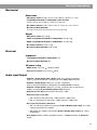
Where to find...
For your records
The product serial number is located on the bottom of each component:
PS1 power stand serial number:___________________________________________________
L1 Cylindrical Radiator™ loudspeaker serial number:_________________________________
B1 bass module (optional) serial number:___________________________________________
B1 bass module (optional) serial number:___________________________________________
Dealer name:___________________________________________________________________
Dealer phone:____________________ Purchase date:_______________________________
Please keep your sales receipt together with this owner’s guide.

7
English Deutsch FrançaisDansk Español Italiano SvenskaNederlandsDansk Italiano SvenskaDeutsch NederlandsEnglish FrançaisEspañol
Setup
Before you begin
Thank you for purchasing one of the Bose
®
Personalized Amplification System™ family of
products. This new revolutionary technology brings the benefits of the intimate acoustic
concert to amplified performances.
70
“A Mark of Quality”
Benefits for musicians
• You control the sound – Just as in an unamplified performance, you, and no one else,
control the sound. You will no longer wonder how you sound to your fellow musicians or to
your audience.
• Quick and easy setup – The Personalized Amplification System™ product is easy to
carry and can be set up in minutes, not hours. This frees you from the time-consuming,
draining, and frustrating effort required to properly set up conventional sound equipment.
• Dramatically improved performance – Performance and enjoyment dramatically
improve because you will no longer struggle to hear yourself and the other musicians.
Benefits for the audience
• Creates excitement and emotion – The enhanced performance of the musicians
creates the kind of excitement and emotion that is valued by music lovers more than
anything else.
• You hear what the audience hears – For the first time, musicians hear what their
audiences hear and thus, are unlikely to play at uncomfortable sound levels.
• The music is naturally dynamic – The softest to the more intense passages can be
heard and enjoyed.
• You look better – There is less clutter on the stage and more room.
• Sound reproduction unlike before – Audience members report that the clarity and
excitement that come from hearing the accurate reproduction of sound from each
instrument, and from hearing the sound of each instrument in its position on stage
(as opposed to mono or even stereo mix of all instruments) is unlike anything they have
heard before in an amplified performance.
For more information
This owner’s guide provides only basic setup and operating instructions. For more
in-depth information on using this system, including tips, techniques, and frequently asked
questions, please visit www.bose.com/musicians on the Internet.

8
Setup
English Deutsch FrançaisDansk Español Italiano SvenskaNederlandsDansk Italiano SvenskaDeutsch NederlandsEnglish FrançaisEspañol
Unpacking
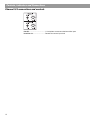
Your Personalized Amplification System™ products are delivered to you in two cartons.
One carton contains the PS1 power stand, AC power cord, R1 remote control with cable,
protective plug, Owner’s and Quick Setup guides, PS1 carrying bag, CD-ROM, and a spare
fuse. The other carton contains the L1 Cylindrical Radiator™ loudspeaker and carrying bags
(Figure 1).
If you purchased B1 bass modules, they will be packaged separately with a carrying bag and
a (blue) B1 bass module 4-wire cable.
WARNING:
To avoid danger of suffocation, keep the plastic bags out of the reach of children.
Note:
Now is a good time to record the serial number on the bottom of these components, on
page 6 of this guide. Refer to page 24 for registration information.
Figure 1
System components
PS1 power stand
Upper and Lower L1 Cylindrical
Radiator™ loudspeaker
R1 remote
control
Remote
control cable
AC power cord
Figure 2
Included equipment
The Bose
®
Personalized Amplification System
™
Family Of Products
Free Personalized Support
877-335-2673
www.bose.com/musicians
Thank you for your purchase.
Many new owners have told us that their first experience
using this system was a pivotal point in their musical life. They describe hearing and
playing in a completely new way.
Our advice for new owners is this: Get to know the product and learn how to get the
most out of this new approach to live amplified music.
We offer free personalized support to help you with the process of setting up and
optimizing your sound. This free service is available by phone or online.
Call us toll-free at 877-335-2673to speak one-on-one with a professional
musician
who specializes in the Personalized Amplification System
™
family of products.
Visit us online at www.bose.com/musicians,
where an enthusiastic
community of owners and support staff are ready to answer your questions.
Browse the site to find the information you need, or join the conversation on
our Message Boards.
These free support options will help you get
up to speed quickly, so you can
begin enjoying the full potential of this new approach.
The Live Music Technology Group
Bose Corporation
Live Performances Calendar
When you register, you could be eligible to post your gigs
on the Live Performances Calendar on our website.
Visitwww.bose.com/musicians to check out our
featured artists and find a performance near you.
Carrying bags for the L1 Cylindrical
Radiator
™ loudspeaker
Carrying bag for the
PS1
power stand
Protective plug
Owner’s Guide and
Quick Setup Guide
CD-ROM
Spare fuse
Warranty
sheet
Note: For a complete list of optional equipment and accessories please visit
www.bose.com/musicians.
Figure 3
Optional equipment
B1 bass module
Carrying bag for B1 bass module
B1 bass module 4-wire cable (blue)

9
Setup
Svenska Nederlands Italiano Français Español Deutsch Dansk EnglishDanskDeutschItalianoNederlandsSvenska Français Español English
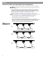
Placing the product in the right location for your performance
Before you start to assemble this product, it is a good idea to find the best location for it.
WARNING:
The completed unit weighs about 60 lb. Moving the completely assembled unit is
not recommended.
Placing the PS1 power stand in the right location is an important step in the process of
setting up this product to create your own individualized sound. Determining the best
location for your performance depends on several things: size of staging area, number of
performers, and if you will be sharing the PS1 power stand connections.
The following guidelines should get you started in setting up for a concert or show.
Note:
For more information on setting up your Personalized Amplification System™ product to
achieve an individualized sound, visit www.bose.com/musicians on the Internet.
• Place the product at the rearmost part of the performance area or stage.
• If possible, position the product behind the performer.
• If you are part of a group, avoid crowding together on stage. Allow some distance
(ideally 7-8 feet) between you and the L1 Cylindrical Radiator™ loudspeaker and another
performer. This allows the sound to wrap around performers and reflect off adjacent
surfaces of the room, creating a more pleasing room-filling sound.
Figure 4
Placement
recommendations
Drummer
Keyboard
Bass
7-8 ft 7-8 ft
Drummer
Keyboard
Bass
Drummer
Keyboard
Bass
7-8 ft
OK
Better
Best
Wall
Wall
Wall
3 ft 3 ft 3 ft
5 ft 5 ft 5 ft
3 ft
3 ft
5 ft
5 ft
7-8 ft
7-8 ft

10
Setup
English Deutsch FrançaisDansk Español Italiano SvenskaNederlandsDansk Italiano SvenskaDeutsch NederlandsEnglish FrançaisEspañol
Product assembly
1. Place the PS1 power stand on the floor. Place it on
a flat, dry, stable surface at the rearmost part of the stage,
handle facing forward, behind the performer.
WARNING: The completed unit
weighs about 60 lb.
Moving the completely
assembled unit is not
recommended.
For placement guidelines, see
“Placing the product in the
right location for your perfor-
mance” on page 9.
2. Insert the bottom section of the
L1 Cylindrical Radiator™
loudspeaker into the PS1 power
stand. You should hear a soft click
when it is properly seated and locked
in place.
4. Connect the R1 remote control to the PS1
power stand. Plug the R1 remote control cable into
either end of the remote. Plug the other end into the
Remote jack on the PS1 power stand.
6. Plug in the PS1 power stand and turn it on. Plug
the female end of the power cord into the AC Mains
jack on the PS1 power stand. Plug the other end into an
AC (mains) receptacle.
3. Mount the top section of the L1 Cylindrical
Radiator™ loudspeaker. Place one foot on the PS1
power stand to support your back. Insert the bayonet on
the top section into the channel that
runs along the back of the bottom
section. Lower the top section until it
is flush with the top of the bottom
section. You should hear a soft click
as the top section locks in place.
Your Personalized Amplification System™
product is now set up and ready for the
addition of other equipment.
• See “Connecting a B1 bass module to the PS1
power stand (optional)” on page 12.
• See “Using an effects processor” on page 19.
5. Place the R1 remote control within reach of
your performance position. This will allow you to
both hear your performance and to control it directly.
Note: If you power up the system without the R1 remote
control, it will function as if all the knobs on the R1 remote
control are at center position (12 o’clock).
Note: Electrical connections
between the PS1 power stand
and L1 Cylindrical Radiator™
loudspeaker are made
automatically as you
assemble the product.
CAUTION: Bose recommends using a quality surge
suppressor on all electronic equipment. Voltage
variations and spikes can damage electronic
components in any system. A quality suppressor,
which can eliminate the vast majority of failures
attributed to surges, may be purchased at
electronics stores.

11
Setup
Svenska Nederlands Italiano Français Español Deutsch Dansk EnglishDanskDeutschItalianoNederlandsSvenska Français Español English
Disassembly
WARNING: Before disassembly, turn the power off and then remove the AC power cord and all
other cables from the PS1 power stand.
R
emove the top L1 Cylindrical Radiator
TM
l
oudspeaker section
Place one foot on the PS1 power stand to support
y
our back. Firmly grasp the top section with one
hand. Using your other hand, press the release
button with your thumb and remove the top section
f
rom the bottom section.
R
emove the bottom L1 Cylindrical
R
adiator loudspeaker section
Using your foot, push down on the PS1 power
s
tand treadle and lift the bottom L1
C
ylindrical Radiator™ loudspeaker section
up and out of the PS1 power stand.

12
Setup
English Deutsch FrançaisDansk Español Italiano SvenskaNederlandsDansk Italiano SvenskaDeutsch NederlandsEnglish FrançaisEspañol
Connecting a B1 bass module to the PS1 power stand (optional)
The %%DVV0RGXOH$PS287 jack on the PS1 power stand can adequately drive one or
two B1 bass modules. B1 bass modules can be placed on the floor vertically or horizontally.
Up to four modules can be stacked when placed horizontally (Figure 1).
CAUTION:
Do not connect more than two B1 bass modules to the B1 Bass Module (Amp 3
OUT) jack on the PS1 power stand. Driving more than two B1 bass modules from the B1 Bass
Module (Amp 3 OUT) output will improperly load the amplifier in the PS1 power stand, resulting
in less than full system performance.
CAUTION:
Only B1 bass modules should be used in the B1 Bass Module (Amp 3 OUT) jack.
Figure 5
Bass module orientations
B1 bass modules can
be stacked in a column
of up to four, maximum
B1 bass modules can
be placed vertically or
horizontally
Connecting one B1 bass module
Insert one end of the B1 bass module 4-wire cable into one of the jacks on the rear panel
of the B1 bass module. Insert the other end of the 4-wire cable into the %%DVV0RGXOH
$PS287 jack on the PS1 power stand connector panel.
Figure 6
B1 bass module
B1 bass module 4-wire cable (blue)
To connect, push the plug
into the jack and rotate it
clockwise to lock it.
To disconnect, slide back the metal tab on the
body of the plug, rotate the plug counterclockwise
and pull it out of the jack.
To
B1 Bass Module
(Amp 3 OUT)
Note: The B1 bass module connector will click softly upon being properly engaged.
CAUTION:
A B1 bass module cannot be shared between two PS1 power stands.

13
Setup
Svenska Nederlands Italiano Français Español Deutsch Dansk EnglishDanskDeutschItalianoNederlandsSvenska Français Español English
Connecting two B1 bass modules
Connect the first B1 bass module to the PS1 power stand as shown in “Connecting one B1
bass module.”
Insert one end of the second B1 bass module cable into the unused jack on the rear panel of
the first B1 bass module. Insert the other end of the cable into one of the jacks on the rear
panel of the second B1 bass module.
CAUTION:
Do not connect more than two B1 bass modules to the B1 Bass Module (Amp 3
OUT) jack on the PS1 power stand. Driving more than two B1 bass modules from the B1 Bass
Module (Amp 3 OUT) output will improperly load the amplifier in the PS1 power stand resulting
in poor system performance.
Note:
Use only the supplied (blue) B1 bass module 4-wire cable to connect B1 bass modules
to the PS1 power stand. The PS1 power stand uses the signals on two of the four wires to
automatically sense how many B1 bass modules are connected to it. DO NOT SUBSTITUTE
the supplied cable with a 2-wire speaker cable.
Figure 7
Installation of two B1 bass
modules
To
B1 Bass Module
(Amp 3 OUT)

14
Svenska Nederlands Italiano Français Español Deutsch Dansk EnglishDanskDeutschItalianoNederlandsSvenska Français Español English
Controls, Indicators and Connections
Channel 1/2 connections and controls
Input ..........................................Combination XLR (mic) or ¼-inch phone connector
unbalanced (line) input. Inserting a male XLR connector
sends the input signal to a balanced microphone
preamplifier. Inserting a ¼-inch phone plug sends the input
signal to an unbalanced high-impedance line-level circuit
which is suitable for most instruments such as active or
passive guitars or basses, keyboards, etc. Both inputs can
be adjusted with the Trim control.
Trim 0 to 12 ...............................Controls the input level.
Signal/OL ..................................Indicates signal presence (green) or signal overload (red).
Phantom Off/+24V....................When depressed turns on the +24V phantom power. The
LED lights when phantom power is on.
Preset Select ............................Selects a comprehensive channel equalization, which results
in a “normal” or useful sound when the product is used with
commonly available equipment such as microphones,
musical instruments or sound processors. The selectable
settings from 00 to 99 apply only to channels 1 and 2.
Settings are identical on both channels but are
independently selected. See the preset guide inside the PS1
power stand panel door for a list of available presets.
Line OUT ...................................XLR output for sending to external recording equipment or to
conventional sound mixing consoles (for using the Bose
approach in large venues).
Insert .........................................A TRS line input/output for connecting to external
equipment, such as digital effects processors.
Note:
Use a stereo plug in the Insert jack for connecting send and return signals. The ring
connects to the “Send”; and the tip connects to the “Return”.

15
Controls, Indicators and Connections
Svenska Nederlands Italiano Français Español Deutsch Dansk EnglishDanskDeutschItalianoNederlandsSvenska Français Español English
Channel 3/4 connections and controls
Line IN ....................................... ¼-inch phone connector unbalanced line input
Level 0 to 12 ............................. Controls the source input level

16
Controls, Indicators and Connections
English Deutsch FrançaisDansk Español Italiano SvenskaNederlandsDansk Italiano SvenskaDeutsch NederlandsEnglish FrançaisEspañol
Power amp patch, bass, remote and AC power connections
Amp 1 IN............................................. Amplifier 1 input jack
Amp 2 IN............................................. Amplifier 2 input jack
Amp 3 IN............................................. Amplifier 3 input jack
All Amps IN ........................................ Input jack to all amplifiers
Amp 1 OUT......................................... Amplifier 1 output jack
Amp 2 OUT......................................... Amplifier 2 output jack
B1 Bass Module (Amp 3 OUT).......... Bass output (amplifier 3 output) jack. Used to drive
one or two B1 bass modules
Bass - Line OUT ................................ Balanced or unbalanced bass signal output for
extended bass configurations
Note:
For more information on extended bass configurations, visit www.bose.com/musicians.
Data IN ............................................... Digital data input. Used for updating product software
Data OUT ........................................... Channel 1/2 digital output
Remote............................................... Input connection for the R1 remote control
AC Mains............................................ 3-conductor power cord connections
Fuse.................................................... AC power fuse
On/Off................................................. PS1 power stand on/off switch
Used only when an L1
Cylindrical Radiator™
loudspeaker is NOT
installed in the PS1
power stand.

17
Controls, Indicators and Connections
Svenska Nederlands Italiano Français Español Deutsch Dansk EnglishDanskDeutschItalianoNederlandsSvenska Français Español English
R1 remote control features
00
-12 +12
CH2
HIGH
MID
LOW
MASTER
LEVEL
CH1
SIG / OLSIG / OL
0
0
0
0
-12 +12 -12 +12
-12 +12
-12 +12 -12 +12
0 12
0 12
0 12
CH1/CH2 HIGH -12 to +12 ...............Cuts (-) or boosts (+) high-frequency sounds
CH1/CH2 MID -12 to +12 .................Cuts (-) or boosts (+) mid-frequency sounds
CH1/CH2 LOW -12 to +12................Cuts (-) or boosts (+) low-frequency sounds
CH1/CH2 LEVEL 0 to 12...................Adjusts the channel’s volume level
MASTER 0 to 12................................Adjusts volume level of all channels

18
Svenska Nederlands Italiano Français Español Deutsch Dansk EnglishDanskDeutschItalianoNederlandsSvenska Français Español English
Operating Instructions
Producing individualized sound
This product will produce sound whether it is properly adjusted or not. However, if you take a
few moments to follow a simple startup procedure, you can optimize the sound for a superior
presentation based on your performance style and preferences.
Unless you make big changes in how you perform, this is typically a one-time event.
1. Set all Trim and Level controls on the PS1 power stand to zero (0).
2. Set the MASTER and all LEVEL controls on the R1 remote control to zero (0).
3. Set the Power switch to On.
CAUTION:
The peak inrush current for the system is approximately 32 amps. If more than one
system is plugged into the same AC circuit, make sure you stagger the turn-on times. This can
prevent tripping the circuit breaker or blowing the house mains fuse.
4. Plug your microphone or instrument into the Channel 1 or 2 Input jack. If phantom
power is required for your microphone (condenser or electret/condenser type), depress
the Phantom power button.
Note:
You can dial in a preset to improve the tone of many commonly used microphones and
musical instruments. See the preset list inside the rear panel door for a list of supported
instruments.
5. Sing or play as loud as you would in a performance while following steps 6 and 7.
6. Adjust the Trim control so that the Signal/OL indicator goes from unlit to green, and
finally to occasionally blinking red. Make sure that your instrument is at the highest vol-
ume setting that you are planning to use. For vocalists, sing as loud as you would during
the performance to achieve the maximum expected input signal.
7. Adjust the LEVEL control on the R1 remote control and make the SIG/OL indicator go
from unlit to green, and finally to occasionally blinking red.
That’s it! You’re done! When you go to your concert or show:
•Use the CH 1 and 2 LEVEL controls on the R1 remote control to adjust the Channel 1 and
2 volume level.
•Use the MASTER control on the R1 remote control to adjust the volume level of all
outputs.
•Use the HIGH, MID, and LOW equalization controls on the R1 remote control to adjust the
timbre of your sound.
Initially, keep the R1 remote control close at hand. This allows you to conveniently adjust the
volume level when you first start playing. Later, you can move it out of the way or backstage
once the system is performing the way you want it to.
Note:
For more information on presets and amplifying the true sound of your instrument(s),
please visit www.bose.com/musicians.
Using input channels 3 and 4
The Channel 3 and 4 inputs are optimized for 0 dB line-level signals, such as the signals from
an effects processor, mixer, or CD player. Simply connect the equipment to the PS1 power
stand and raise the output level using the Channel 3 and 4 Level control on the rear panel of
the PS1 power stand.

19
Operating Instructions
Svenska Nederlands Italiano Français Español Deutsch Dansk EnglishDanskDeutschItalianoNederlandsSvenska Français Español English
Using an effects processor
Serial connection method
With the serial method, the complete signal is routed directly into one or more effects
processors. Serially connected effects processors are connected in a chain and the signal is
processed sequentially. Nearly all “stomp boxes” for guitars work this way, such as, an
overdrive followed by a reverb.
In a serial effect hookup, the order in which effects are connected together matters. For
example, it makes a big difference whether you run first through the overdrive and then the
reverb, or first through the reverb and then through the overdrive.
Note:
Always connect electronic equalizers, compressors, and limiters in serial.
Parallel connection method
The parallel method is mainly implemented in conventional mixers through “aux” or “effect”
send/return connections and controls. Effects processors get the original
(unprocessed) signal as an input. The output of effects processors is then added together
and summed with the original clean signal. There is a component of the original signal
present in the output, such as reverb and delay, which are used for vocals.
Note:
The parallel method mixes the original signal with the processed version. In the case of an
equalizer, this generates highly undesirable interference and potential phase cancellation. Many
digital effects processors have an internal processing delay, which is applied to the signal, even
if no effect setting is applied. Mixing this delayed output with the original signal can result in
unintended comb filtering.
IMPORTANT: When using an effects processor, determine and use the proper connection
method (serial or parallel) for your application. Some effects MUST be hooked up in serial.

20
Operating Instructions
English Deutsch FrançaisDansk Español Italiano SvenskaNederlandsDansk Italiano SvenskaDeutsch NederlandsEnglish FrançaisEspañol
Using a serial effects connection with the PS1 power stand
Note: Connecting an effects unit in serial requires a TRS split “insert” cable (with a ¼-inch TRS
connector on one side, and two mono ¼-inch phone connectors on the other). This type of cable
is readily available at most musical instrument stores and on the Internet.
1. Insert the TRS plug into the Channel 1 Insert jack on the PS1 power stand.
2. Connect the ¼-inch mono plug (labeled “send”, “ring”, or “right”) to the input of the
effects processor.
3. Connect the other ¼-inch mono plug (labeled “return”, “tip”, or “left”) to the output of the
effects processor.
4. Adjust the effects level and mix of the effects processor.
Note:
A very high output from the effects processor can overload the input of the PS1 power
stand. If the LED on the remote turns red, even if the channel LEVEL control on the R1 remote
control is below the 12 o’clock position, reduce the output level of your effects processor.
Note:
The effects processor does interrupt the audio path. This may result in no audio output if
the effects processor is turned off. To use a “clean” signal, do not turn the effects processor off,
but put it in bypass mode.
Figure 8
Using a serial effects
connection
TRS
TRS split “insert” cable
Connect to
Channel 1 Insert
(Return, Left or Tip)
Connect to Effects Unit
OUTPUT
(Send, Right, or Ring)
Connect to Effect Unit INPUT
Digital Effects Unit
PS1 power stand

21
Operating Instructions
Svenska Nederlands Italiano Français Español Deutsch Dansk EnglishDanskDeutschItalianoNederlandsSvenska Français Español English
Using parallel effects connection with the PS1 power stand
Note: Connecting an effects unit in parallel requires one ¼-inch unbalanced (instrument) cable,
one mono ¼-inch phone (M) to dual mono ¼-inch phone (F) “Y” cable adaptor, and one TRS split
“insert” cable (with a ¼-inch TRS connector on one side and two mono ¼-inch phone connec-
tors on the other).
1. Insert the TRS plug into the Channel 1 Insert jack on the PS1 power stand.
2. Connect both ¼-inch plugs from the “insert” cable into both receptacles on the “Y” cable
adaptor.
3. Connect the plug of the “Y” cable adapter into the input of the effects processor.
4. Connect the ¼-inch unbalanced (instrument) cable from the output of the effects
processor to Channel 3 Line IN of the PS1 power stand.
5. Set the effects level of the processor to full and turn the mix level of the effects processor
to full “wet”.
6. Adjust the Channel 3 Level control of the PS1 power stand for the desirable effects mix.
Figure 9
Using a parallel effects
connection
TRS split “insert” cable
1/4-inch Instrument Cable
Mono 1/4-inch Phone (M) to
dual mono 1/4-inch Phone (F)
“Y” cable adaptor
Connect to Effect Unit INPUT
Digital Effects Unit
Connect to Effects
Unit OUTPUT
Connect to
Channel 3 Line IN
Connect to
Channel 1 Insert
PS1 power stand

22
Svenska Nederlands Italiano Français Español Deutsch Dansk EnglishDanskDeutschItalianoNederlandsSvenska Français Español English
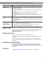
Troubleshooting
If you experience problems while using this product, try the following solutions. If you still
can’t solve the problem, please call the Bose
®
Live Music Product and Technical Support
Team direct at 877-335-2673 to arrange for service.
Recommended troubleshooting tools:
• Portable voltmeter • B1 bass module 4-wire cable (blue)
• Cable tester • Spare T15AH fuses
• AC outlet tester • Spare AC power cord
• XLR and ¼-inch phone plug cables
Problem What to do
System is plugged in,
power switch is on, but
power LED is off
• Make sure you have power at the AC outlet. Try operating a lamp or other equipment
from the same AC outlet or test the outlet using an AC outlet tester.
• Make sure the PS1 power stand’s power cord plug is fully inserted into the AC outlet.
• Check the line fuse on the PS1 power stand.
Power LED is on (green),
but no sound
• Make sure volume control is turned up on your instrument.
• Make sure the applicable level control is turned up (Trim, or Channel 3/4 Level on the
PS1 power stand; CH 1/2 LEVEL and MASTER level on the R1 remote control).
• Make sure your instrument is plugged into the Channel 1/2 Input or Channel 3/4 Input
jack.
• Connect your instrument to the PS1 power stand using a different cable.
• Plug your instrument into a different amplifier to make sure the instrument is working.
Power LED is red while the
PS1 power stand is on
• Please call Bose Live Music Customer Support at (877) 335-2673 for assistance.
House circuit breaker
keeps tripping
• If you have more than one PS1 power stand plugged into the same AC circuit, stagger
the turn-on times. Each PS1 power stand has an inrush current of about 32 amps when
turned on.
• If you have more than three PS1 power stands plugged into a single 15 amp circuit,
move some systems to another AC circuit. Each PS1 power stand can draw 5 amps or
more when playing at high volumes for long periods of time.
With nothing plugged into
the audio input or output
connectors on the rear
panel of the PS1 power
stand, a slight hum or buzz
is heard from the L1 or B1
• Using an AC outlet tester, test the AC outlet that the PS1 power stand is plugged into
for reversed or open (hot, neutral, and/or ground) contacts.
• If using an extension cord, make sure that the cord is also tested as above.
B1 bass module is plugged
in, but no bass audio is
heard
• Make sure you are using the (blue) B1 bass module 4-wire cable included with the B1
bass module.
• Make sure that the B1 bass module cable is plugged into the B1 Bass Module (Amp 3
OUT) jack on the PS1 power stand.
• Try a different 4-wire cable.
• Check that the B1 bass module cable connectors are fully engaged in the jacks.
• If available, try a different B1 bass module.
B1 bass module sounds
out of balance with the
system
• Make sure you are using the (blue) B1 bass module 4-wire cable included with the B1
bass module package.
• Make sure that the B1 bass module grille is facing forward toward the musicians and
audience.
Page is loading ...
Page is loading ...
Page is loading ...
Page is loading ...
Page is loading ...
Page is loading ...
-
 1
1
-
 2
2
-
 3
3
-
 4
4
-
 5
5
-
 6
6
-
 7
7
-
 8
8
-
 9
9
-
 10
10
-
 11
11
-
 12
12
-
 13
13
-
 14
14
-
 15
15
-
 16
16
-
 17
17
-
 18
18
-
 19
19
-
 20
20
-
 21
21
-
 22
22
-
 23
23
-
 24
24
-
 25
25
-
 26
26
-
 27
27
-
 28
28


Bose Personalized Amplification System Operating instructions
- Category
- Audio amplifiers
- Type
- Operating instructions
Ask a question and I''ll find the answer in the document
Finding information in a document is now easier with AI
Related papers
-
Bose Professional L1® Model 1 User guide
-
Bose RC-18S User manual
-
-
Bose PM8500 User manual
-
Bose Professional L1 Model II Owner's manual
-
-
Bose Professional T1 ToneMatch® audio engine Owner's manual
-
Bose S1 Pro Owner's manual
-
-
Bose Professional S1 Pro User manual
