Page is loading ...

Manual # P80180001D - Date:2013/02/27
Ÿ
Ÿ
NOTE TO ASSEMBLER / INSTALLER:
Leave this manual with the consumer.
NOTE TO CONSUMER:
Keep this manual for future reference.
RECORD YOUR SERIAL # __________________
(see silver CSA label on main body of grill)
IMPORTANT:
Ÿ
OPERATOR'S MANUAL
FREE HELP
FROM THE GRILL EXPERTS
Do not return to the store. At Grand Hall we're
the experts on this product and trained to help
you with:
Assembly questions
Grill operation
Replacement of damaged or missing parts
Ÿ
Ÿ
Ÿ
visit www.grandhall.com or call:
1-877-934-7455
Monday - Friday 8:00am-4:30pm CST
WARNING
! !
Failure to comply with these instructions could
result in a fire or explosion that could cause
serious bodily injury, death or property damage.
Whether this grill was assembled by you or
someone else, you must read this entire manual
before using your grill to ensure the grill is
properly assembled, installed and maintained.
Use your grill at least 3 feet away from any
wall or surface. Use your grill at least 3 feet
away from combustible objects that can melt or
catch fire such as vinyl or wood siding, fences
and overhangs or sources of ignition including
pilot lights on water heaters and live electrical
appliances.
THIS GAS APPLIANCE IS DESIGNED FOR OUT-
DOOR USE ONLY.
Never use your gas grill in a garage, porch,
shed, breezeway or any other enclosed area.
Never obstruct the flow of ventilation air
around your gas grill housing.
Never disconnect the gas regulator or any gas
fitting while your grill is lit. A lit grill can ignite
leaking gas and cause a fire or explosion which
could result in property damage, personal injury
or death.
Ÿ
Ÿ
Ÿ
Ÿ
Ÿ
Ÿ
Ÿ
Liquid Propane Gas (LPG) Grill Island
Model HGI08ALP-1
Natural Gas (NG ) Grill Island
Model HGI08ANG-1

Table of Contents
Primary Safety Warnings...........................1-3
Pre-Assembly Instructions..............................3
Part Diagrams and Lists..........................4-8
Assembly Instructions...............................9-10
Use & Care Instructions:
• Gas Safety and Leak Tests............11-13
• Natural Gas Connection..........................14
• Lighting Instructions............................15-16
• Troubleshooting.........................................16
• Rotisserie Instruction...........................17-19
• Cleaning and Maintenance................20-21
• Cooking Guide...................................A1-A5
• Frequently Asked Questions............A6-A7
Warranty Terms............................Back Cover
2
DANGER
!
!
1.
2.
3.
4.
If you smell gas:
Shut off gas to the appliance.
Extinguish any open flame.
Open lid.
If odor continues, keep away from
the appliance and immediately call
your gas supplier or your fire
department.
WARNING
! !
WARNING
! !
This appliance, when installed, must be electri-
cally grounded in accordance with local codes
or, in the absence of local codes, with the
National Electrical Code, ANSI/NFPA 70, or the
Canadian Electrical Code, CSA C22.1.
Keep any electrical supply cord and the fuel
supply hose away from any heated surfaces.
•
•
WARNING
! !
Do not store or use gasoline or other
flammable liquids or vapors in the vi-
cinity of this or any other appliances.
An LP cylinder not connected for use
shall not be stored in the vicinity of
this or any other appliance.
1.
2.
•
•
•
•
LPG models must be used with Liquid Propane
Gas and the regulator assembly supplied.
Natural Gas models must be used with Natural
Gas only. Any attempt to convert the grill from
one fuel type to another is extremely hazardous
and will void the warranty.
Keep gas regulator hose away from hot grill
surfaces and dripping grease. Avoid unneces-
sary twisting of hose. Visually inspect hose prior
to each use for cuts, cracks, excessive wear or
other damage. If the hose appears damaged do
not use the gas grill. Call Grand Hall at 1-877-
934-7455 for a certified replacement hose.
California Proposition 65
Combustion byproducts produced when using
this product contain chemicals known to the State
of California to cause cancer, birth defects, or other
reproductive harm.
Brass components on the grill, such as hose
fittings, propane cylinder valves (sold separately)
and burner valve stems, contain lead which is
known to the State of California to cause cancer,
birth defects, or other reproductive harm.
Never use charcoal or lighter fluid in this gas grill.
Failure to comply with these instructions could
result in a grease fire or explosion that could cause
serious bodily injury, death or property damage.
The Grease Tray must be visually inspected be-
fore each grill use. Remove any grease and wash
Grease Tray with a mild soap and warm water
solution. Failure to comply with these instruc-
tions could result in a grease fire or explosion
that could cause serious bodily injury, death or
property damage.
•

Pre-Assembly Instructions For Your Safety
Spiders and small insects can spin webs and nest
in the grill Burner Tubes during transit and ware-
housing which can lead to a gas flow obstruction
resulting in a fire in and around the Burner Tubes.
This type of "FLASHBACK FIRE" can cause serious
grill damage and create an unsafe operating con-
dition for the user.
To reduce the chance of FLASHBACK FIRE
you must clean the Burner Tubes as follows
before initial use. Also do this at least once a
month in summer and fall or whenever spiders are
active in your area, and if your grill has not been
used for an extended period of time.
WARNING
! !
Failure to comply with these instructions may
result in a hazardous situation which, if not
avoided, may result in injury.
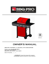
For safe operation ensure the Gas Valve Assembly
Orifice is inside the Burner Tube before using your
grill. See figure. If the Orifice is not inside the
Burner Tube, lighting the Burner may cause explo-
sion and/or fire resulting in serious bodily injury
and/or property damage.
METHOD 1: Bend a stiff wire or wire coat
hanger into a small hook as shown and run
the hook through the Burner Tube and inside
the Burner several times to remove debris.
METHOD 2: Use a bottle brush with a flexible
handle and run the brush through the Burner
Tube and inside the Burner several times to
remove any debris.
METHOD 3: Use an air hose to force air through
each Burner Tube. The forced air should pass
debris or obstructions through the Burner and
out the Ports.
TO CLEAN BURNER TUBE,
INSERT HOOK
HERE
Burner Tube
9
Orifice
Burner TubeGas Valve Assembly
Carefully lift each Burner up and away from the Gas
Valve Orifice.
Check and clean Burner/Venturi Tubes for insects
and insect nests. A clogged tube can lead to a fire
beneath the grill.
Refer to the figure below and perform one of
these 3 cleaning methods:
Remove the screws from the rear of each Main
Burner using a Phillips Head Screwdriver.
1.
2.
3.
4.
3
Burner Port
Foot
To expedite the assembly process follow these
general guidelines:
Grill Information Center 1-877-934-7455
8am-4:30pm CST, Monday through Friday
Grill Installation Codes
The installation must conform with local codes or, in the
absence of local codes, with the National Fuel Gas Code,
ANSI Z223.1/NFPA 54, Storage and Handling of Lique-
fied Petroleum Gases, ANSI/NFPA58,Natural Gas and
Propane Installation Code, CSA B149.1, Propane Stor-
age and Handling Code, B149.2.
Phillips Head Screwdriver
Tools Required for Assembly :
protective work gloves
While it is possible for one person to unpack this gas
grill, obtain assistance from another person when
handling the large pieces.
Use the Hardware and Part Diagrams to ensure all
items are included and free of damage.
Do not assemble or operate the grill if it appears dam-
aged. If there are damaged or missing parts when
you unpack the shipping box or you have questions
during the assembly process, call the:
•
•
1.
WARNING
! !
Do not store spare LP cylinder within
10 feet (3m) of this appliance.
Do not store or use gasoline or other
flammable liquids and vapors within 25
feet (8m) of this appliance.
When cooking with oil/grease, do not
allow the oil/grease to get hotter 350°F
(177°C)
Do not leave oil/grease unattended.
4.
2.
3.
CAUTION
!
When using electrical appliances, basic
safety precautions should always be used.
!

* Two Batteries/AA included in the Hardware Pack.
Hardware Pack Parts List for Model HGI08ALP-1 & HGI08ANG-1
Phillips Head Screw 1/4"x3/8"
Qty. 4
Part # S112G0406E
Wrench
Qty.1
Part # P05515017L
Already packed in the Cooking Components Box
Wing Bolt 1/4"x1/2"
Qty. 2
Part # S233G04084
Hardware already installed on the Tank Holder
4
PART # PART DESCRIPTION QTY PURPOSE OF PART
P06016003A Hardware Pack 1 For use in assembly (Gril)
S112G0406E Phillips Head Screw 1/4"x3/8" 4 Install Cart Frame to Grill Left Cart Legs
S233G04084 Wing Bolt 1/4"x1/2" 2 Secures Gas Tank to Tank Holder
P05515017L Wrench 1 Adjust level on Island Assembly Set
Already Installed on Tank Holder
Already packed in the Cooking Components Box
Hardware Pack Diagram for Model HGI08ALP-1 & HGI08ANG-1

Parts Diagram for Model HGI08ALP-1 & HGI08ANG-1 Grill
5
82
65
64
66
67
75
53
76
55
77
58
79
78
1
2
3
4
5
6
9
7
8
13
15
18
25
26
24
27
28
29
30
31
34
49
57
56
43
47
54
52
50
51
41
46
45
48
42
39
37
36
35
22
17
16
14
12
11
23
71
44
49
60
10
38
72
59
69
61
62
40
40
74
73
33
70
68
19
21
20
32
18a
63
52a
52b

Parts List for Model HGI08ALP-1 & HGI08ANG-1 Grill
6
KEY DESCRIPTION PART # QTY
1 Lid Assembly P001474134 1
2
Temperature Gauge P00601297A 1
3
Lid Handle P00205069M 1
4 Protective Pad P05518011 I 2
5 Cooking Rack/Secondary P01516004J 1
6 Cooking Grid 13" P01604013B 2
7 Cooking Grid 6.5" P01604031B 1
8 Burner P020080324 3
9 Infrared Burner Assembly P020050104 1
10 Thermocouple P05305019A 1
11
Savor Plate
®
P017080074 3
12 Burner Bracket P0220342DD 1
13 Rotisserie Burner Assembly P02007068A 1
14 Rotisserie Burner Wind Shield P06906046B 1
15 Rotisserie Burner Electrode P02614025A 1
Rotisserie Burner Orifice (LPG) P06534005A 1
Rotisserie Burner Orifice (NG) P06534009A 1
17 Rotisserie Burner Extension Tube P03717045B 1
18 Bowl P0071334P4 1
18a Bowl Wind Shield P069060754 1
19
Thermocouple Bracket
P03343008C
1
20
Cart Panel Bracket A
P03327038C
1
21
Cart Panel Bracket B
P03327039C
1
22 Burner Heat Shield P07523003P 1
23 Grease Tray Heat Shield P069040204 1
Gas Valve/Manifold Assembly/Grill (LPG) Y0060412 1
Gas Valve/Manifold Assembly/Grill (NG) Y0060663 1
25 Electric Wire Set P02615103A 1
26 Gas Collector Box with Electrode P02609010B 3
27 Control Panel Extension P0290976HS 1
28 Control Panel, Upper/Grill
P0290977FS
1
29 Control Panel/Grill P0290978FA 1
30 Control Knob P03411503L 3
31 Control Knob For Back Burner/Infrared Burner P03411513L 2
32 Control Knob Spring P05504021A 5
33
Cart Frame, Left/Grill P01303016B 1
34 Control Knob Seat P03415014S 5
35 Lighting Stick Assembly P05507008A 1
36 Regulator with Hose (LPG) P03601004A 1
37 Grease Tray/Grill P02717454A 1
38 Bowl Support Bracket, Left P01301007K 1
39
Cart Panel, Top
P07801027A
1
40 Cart Panel, Lower/Left & Middle
P07604016B 2
41 Cart Panel, Right
P07620001D 1
42 Cart Frame, Right/Grill
P03344007D 1
43 Cart Panel, Front/Grill
P07621004D 1
44 Cart Frame for Front Panel/Grill
P03344003D 1
45 Cart Panel, Rear/Left/Grill
P07702082M 1
46 Cart Panel, Rear/Right/Grill
P07702083M 1
47
Cart Frame, Front/Grill P00907003C 1
48
Cart Frame, Rear/Grill
P00907004C
1
49
Drawer Slide Set P05516012C 1
50
Door P04301030J 1
24
16

Parts List for Model HGI08ALP-1 & HGI08ANG-1 Grill
7
Important: Use only Grand Hall certified replacement parts. The use of any part that is not a factory
authorized part can be dangerous and will also void your product warranty. Keep this Operator's Manual
for convenient referral and for part replacement.
To Order Grand Hall Certified Replacement Parts, Call 1-877-934-7455
To obtain the correct replacement parts for your grill, please refer to the part numbers in this parts list.
The following information is required to ensure you receive the correct parts:
1. Model and Serial Number (see CSA label on grill)
2. Part Number
3. Part Description
4. Quantity of parts needed
KEY DESCRIPTION PART # QTY
51
Door Handle P00215031A 1
52
Tank Tray (LPG) P04009030B 1
52a Cart Basket Bottom (NG) P01001053D 1
52b Cart Basket (NG) P05203007G 1
53
Slide Set P05516013C 1
54
Slide Bracket A P03311011D 2
55
Hose Holder (LPG)
P055360014
1
56
Drawer P01901008I 1
57
Drawer Handle P00215032A 1
58
Protective Cap A P05535008I 1
59
Name Plate P00407031T 1
60
Level Adjuster P05322004A 4
61
Door Bracket, Left P033020274 1
62
Door Bracket, Right P033020284 1
63 Electric Wire/Grill P02616011D 1
64 Savor Plate Bracket, Front P033280504 3
65 Savor Plate Bracket, Rear P033280514 3
66 Back Burner Thermocouple P05305022A 1
67 Back Burner Thermocouple Bracket P033280474 1
68
Grease Draining Plate
P069020094
2
69 Electric Ignitor, 6-port P02502075C 1
70 Electric Ignitor Protector P05545002A 1
71 Grease Tray Handle/Grill P00213012M 1
72 Bowl Support Bracket, Right P01302007K 1
73 Cart Panel, Upper/Left
P01304009D 1
74 Cart Panel, Upper/Middle
P01305009D 1
75
Tank Holder (LPG) P05358002Y 1
76
Grease Tray Heat Shield, Lower
P06903050M
1
77
Door Trim Panel
P07510023H
1
78
L Bracket, Left
P033020314
1
79
L Bracket, Right
P033020324
1
80
NG Regulator
Y0080023
1
81
Hose, 12FT/NG
P03703001A
1
82
Infrared Burner Electrode
P02614057A
1
Cover/Grill
P07002064B
1
Cover/Range
P07002065B
1
Rotisserie Assembly Y0250152 1
Hardware Pack P06016003A 1
Operator's Manual/Grill P80180001D 1

Grill Information Center: If you have questions about assembly or grill operation, or if there are damaged
or missing parts when you unpack this unit from the shipping box, call us 8:00 am - 4:30 pm CST, Monday
through Friday at: 1-877-934-7455
Y0250152 Rotisserie Assembly Parts Diagram
Y0250152 Rotisserie Assembly Parts List
Hardware for Rotisserie
Rot. Screw#10-24x3/4"
UNC
Qty. 2
Part # S112G10124
Rot. Thumbscrew
1/4"x1/2"
Qty. 3
Part # S196G04084
Rot.Washer
Qty. 2
Part # S411G03084
Rot. Nut.#10-24
Qty. 2
Part # S362G10124
KEY
PART#
DESCRIPTION
QTY
Rot. Bushing
Rot. Thumbscrew 1/4"x1/2"
Rot. Collar
Rot. Spit
Rot. Holding Fork
Rot. Motor Bracket
Rot. Motor/AC
Rot. Screw#10-24x3/4"UNC
Rot. Washer
Rot. Nut #10-24
1.
2.
3.
4.
5.
6.
7.
8.
9.
1
3
1
1
2
1
1
2
2
2
P05508092F
S196G04084
P05508091F
P05508175F
P05508090F
P05508174F
P07101048A
S112G10124
S411G03084
S362G10124
1.
2.
3.
4.
5.
6.
7.
8.
9.
10.
7
8
9
3
10
6
2
2
5
4
1
2
8

Assembly Instructions
Install Cart Frame
9
Install Ignitor Battery
Unscrew Ignitor Cap from Control Panel.
Place supplied AA battery into the Ignitor Slot
with positive pole facing you.
Position the Cap and Spring over the AA
battery and tighten onto Control Panel.
3
Spring
Ignitor Cap
Ignitor Slot
AA Battery
Be sure all Control Knobs are set to "OFF"
and open the Grill Lid.
Have your assistant stand behind to the
right of the grill and look toward the front of
the grill bowl. Never put your face inside the
Grill Head.
Press the Ignitor Cap. You should hear a
"clicking" sound. Your assistant should see
a blue spark within each Gas Collector Box.
If a spark is present the Electrode Tips are
properly positioned.
If no spark is seen, the Spark Gap needs
to be adjusted as follows:
With the assistance of another person,
perform this Electrode Check before
proceeding.
This test will ensure that the Spark Electrode Tips
are properly positioned so your grill lights easily
and properly.
4
Spark Electrode Tip
Spark Receiver
Spark Gap
Gas Collector Box
•
•
If the gap between the Spark Electrode
Tip and Receiver is more than 3/16" wide
use long nose pliers to gently squeeze
the Gas Collector Box to narrow gap.
Recheck the Electrode again, if no "clicking"
sound is heard:
AA Battery may be installed backwards.
Electric wires may be loose. Remove
the AA Battery and inspect the Ignitor
Junction Box found behind the Control
Panel and reconnect any loose wires.
-
-
Phillips Head Screw
1/4"x3/8"
Qty.4
Part # S112G0406E
Align the 4 holes in the Cart Frame and the
Cart Frame, Left/Grill. Insert the 4 Phillips
Head Screws 1/4"x3/8" and tighten securely.
1
Connect the Swivel nut of the 12' Natural Gas
Hose to the Inlet fitting of NG Regulator as
shown. Connect the other end of the hose
to the gas supply line.
Connect the 12' Natural Gas Hose
2
12' Natural Gas Hose
NG Hose
Gas Inlet
Inlet Fitting
Swivel Nut
Keep the ventilation openings of the Tank
Tray cabinet free and clear of debris.
Use your grill at least 3 feet away from
any wall or surface.
Do not obstruct the flow of air for combustion
and ventilation.
CAUTION
! !
CAUTION
! !

10
6
Adjust the Grill (On Uneven Surface Only)Install Cooking Components
Place the Savor Plates
®
above the Burners.
Place the Cooking Grids on the ledge
above the Savor Plates
®
.
Place the Secondary Cooking Rack into the
holes on the upper left and right of the Back
Burner frame with the bottom resting in the
slots on either side of
the Grill Bowl.
5
Secondary Cooking Rack
Savor Plates
®
Cooking Grids
WARNING
!
Failure to read and follow the Use and Care
Instructions could result in a fire or explosion that
could cause serious bodily injury, death or prop-
erty damage.
!
Underside view of Grill
Wrench
Level Adjuster
Wrench
Qty.1
Part # P05515017L
Level Adjusters are located on the underside
of the Grill as shown below.
Adjust the 4 preassembled Level Adjusters
using the wrench provided.
- Turn the adjusters clockwise to raise the
height of the Grill.
- Turn the adjusters counterclockwise to lower
the height of the Grill.
Important: For illustration purposes, the Grill
is shown at a tilted angle. FOR YOUR SAFETY
DO NOT TILT your Grill at any time.
Final Grill Assembly Step
When you have finished assembling your grill
be sure that all screws are tightened for safe
operation of your grill.

11
USE AND CARE INSTRUCTIONS
CORRECT LP GAS TANK USE
LP Gas grill models are designed for use with a
standard 20 lb. Liquid Propane Gas (LP Gas) tank (sold
separately). Never connect your gas grill to an LP Gas
tank that exceeds this capacity. A tank of approximately
12 inches in diameter by 18-1/2 inches high is the
maximum size LP Gas tank to use. You must use an
"OPD" gas tank which offers a listed Overfill Preven-
tion Device. This safety feature prevents tank from being
overfilled which can cause a malfunction of the LP Gas
tank.
Never connect an unregulated LP gas tank to your gas
grill. The gas regulator assembly supplied with your gas
grill is adjusted to have an outlet pressure of 11" water
column (W.C.) for connection to an LP gas tank. Only
use the regulator and hose assembly supplied with your
gas grill. Replacement regulators and hose assem-
blies must be those specified by the Manufacturer.
Have your LP Gas dealer check the release valve after
every filling to ensure it remains free of defects.
Always keep LP Gas tank in upright position.
Do not subject the LP Gas tank to excessive heat.
Never store an LP Gas tank indoors. If you store your
gas grill in the garage always disconnect the LP Gas
tank first and store it safely outside.
LP Gas tanks must be stored outdoors in a well-
ventilated area and out of the reach of children.
Disconnected LP Gas tanks must not be stored in a
building, garage or any other enclosed area.
The regulator and hose assembly can be seen by
opening the cart doors. They must be inspected before
each use of the grill. If the hose is damaged in any way,
it must be replaced prior to using the grill again.
Never light your gas grill with the lid closed or before
checking to ensure the burner tubes are fully seated over
the gas valve orifices.
The LP Gas tank must be constructed and marked in
accordance with the Specifications for LP-Gas Cylinders
of the U.S. Department of Transportation (D.O.T.) or the
National Standard of Canada, CAN/CSA-B339, Cylin-
ders, Spheres and Tubes for Transportation of Danger-
ous Goods; and Commission, as applicable.
The LP Gas tank must have a shutoff valve, terminating
in an LP Gas supply tank valve outlet, that is compatible
with a Type 1 tank connection device. The LP Gas tank
must also have a safety relief device that has a direct
connection with the vapor space of the tank.
The tank supply system must be arranged for vapor
withdrawal.
The LP Gas tank must have a collar to protect the tank
valve.
Use of alcohol, prescription or non-prescription
drugs can impair your ability to properly assemble
and safely operate your grill.
Keep fire extinguisher readily accessible. In the
event of a oil/grease fire, do not attempt to extin-
guish with water. Use type B extinguisher or smother
with dirt, sand or baking soda.
In the event of rain, turn off the burners and the gas
supply, and then cover the grill.
Use your grill on a level, stable surface in an area
clear of combustible materials.
Do not leave grill unattended when in use.
Do not move the appliance when in use.
Allow the grill to cool before moving or storing.
Do not use your grill as a heater.
This grill is not intended to be installed in or on
recreational vehicles and/or boats.
The grill is not intended for commercial use.
Never use charcoal or lighter fluid in this grill.
!
Do not store a spare LP-Gas tank under or near
this appliance.
Never fill the tank beyond 80 percent full; and
If the information in "(a)" and "(b)" is not followed
exactly, a fire causing death or serious injury may
occur.
A.
B.
C.
!
WARNING
!
WARNING
!
WIND
DIRECTION
3ft.
3ft.
Never allow children to operate your grill. Do not allow
children or pets to play near your grill. Always supervise
children and pets if they are in the vicinity of the unit.
•
•
•
•
Use your grill at least 3 feet away from any wall or
surface.
Use your grill 3 feet away from any combustible
objects that can melt or catch fire such as vinyl or
wood siding, fences, overhangs (See Diagram Be-
low), or any other sources of ignition; including pilot
lights and live electrical appliances.
Do not use your grill under any overhead combus-
tible construction.
Never use your gas grill in a garage, porch, shed,
breezeway, or any other enclosed area.
In windy conditions, always position the front of the
grill to face oncoming wind to reduce heat and
smoke blowing in your face, and to prevent potential
hazards to yourself and the grill.
•

12
USE AND CARE INSTRUCTIONS
Brush soapy solution onto LP Gas tank in the areas
indicated by the arrows. See diagram.
If growing bubbles appear do not use or move the
LP Gas tank. Call an LP Gas Supplier or your Fire
Department.
NOTE about LP Gas Tank Exchange Programs
Many retailers that sell grills offer you the option of re-
placing your empty LP Gas tank through an exchange
service. Use only those reputable exchange companies
that inspect, precision fill, test and certify their tanks. Ex-
change your tank only for an OPD safety feature-equipped
tank as described in the LP Gas tank section of this
manual.
Ÿ
How to Leak Test your LP Gas Tank
Use a clean paintbrush and a 50/50 mild soap and
water solution.
Ÿ
Ÿ
Ÿ
Ÿ
Ÿ
For your safety:
Leak test new and exchanged LP Gas tanks BEFORE
connecting one to your grill.
Always keep new and exchanged LP Gas tanks in an
upright position during use, transit or storage.
If growing bubbles appear do not use or move the
LP Gas tank. Contact an LP Gas Supplier or your
fire department!
WARNING
!
!
LP Gas Model only:
Secure a 20lb LP Gas Tank to Gas Grill
Slide open the Tank Tray doors (as shown).
Turn your LP Gas Tank Valve clockwise to the closed
or OFF positon.
Unscrew the Wing Bolt from right bracket of tank holder.
Place LP Gas tank into tank holder on the Tank Tray.
Install the tank so the Tank Valve faces the rear right
corner of cabinet.
Insert the Wing Bolt into right bracket of tank holder to
secure the gas tank.
Attach the Regulator with Hose to the gas tank.
Push the Tank Tray door closed.
5
2
.
3
6
"
2
7
.
1
5
"
35"
Note:
All measurements are in inches
Wing Bolt 1/4"x1/2"
Qty. 1
Part # S233G04084
Gas Tank Installation
Tank tray
Tank
Holder
All leak tests must be repeated each time your LP Gas
tank is exchanged or refilled.
When checking for gas leaks do not smoke.
Do not use an open flame to check for gas leaks.
Your grill must be leak tested outdoors in a well-venti-
lated area, away from ignition sources such as gas fired
or electrical appliances. During the leak test, keep your
grill away from open flames or sparks.
Do not use household cleaning agents. Damage to gas
assembly components can result.
Ÿ
Ÿ

13
USE AND CARE INSTRUCTIONS
LP Gas Model only:
Connect Regulator with Hose to your LPG Tank
Turn all Burner Valves to the OFF position.
Inspect the valve connection port and regulator as-
sembly for damage or debris. Remove any debris.
Never use damaged or plugged equipment.
Connect the regulator assembly to the tank valve and
HAND TIGHTEN nut clockwise to a full stop. DO NOT
use a wrench to tighten because it could damage
the Quick Coupling Nut and result in a gas leak/fire
hazard.
Open the tank valve 1/4 to 1/2 of a full turn (coun-
terclockwise) and use a soapy water solution to
check all connections for leaks before attempting to
light your grill. See "Check All Connections for LP
Gas Leaks". If a leak is found, turn the tank valve
off and do not use your grill until the leak is repaired.
Quick
Coupling Nut
CAUTION: When the appliance is not in use the gas must
be turned off at the tank. Place dust cap on cylinder valve
outlet whenever the cylinder is not in use. Only install
the type of dust cap on the cylinder valve outlet that is
provided with the cylinder valve. Other types of caps or
plugs may result in leakage of propane.
Type 1 connection per
ANSI Z21.58-2007/CSA
1.6-2007
Check all connections for LP Gas Leaks
Grill
Disconnecting A Liquid Propane Gas (LPG)
Tank From Your Grill
Make sure the Burner Valves and LP Gas tank valve
are off. (Turn clockwise to close.)
Detach the hose and regulator assembly from the LP
Gas tank valve by turning the Quick Coupling Nut
counterclockwise. Do not use a wrench or any tools
when turning the Quick Coupling Nut.
1. Remove the Drawer and Grease Tray.
Gas Valve/Manifold
Assembly
Regulator
with Hose
(LPG)
LP Gas Tank
Air
shutter
Grill Model
Push tenon down
on one side and up
on the other side to
unlock
Angle to view
orifice and
adjust air shutter
L
R
If you have a gas leak that cannot be repaired by
tightening, turn off the gas at the source, disconnect
fuel line from your grill and call 1-877-934-7455
or your gas supplier for repair assistance.
Never disconnect the gas regulator or any gas
fitting while your grill is lit. A lit grill can ignite
leaking gas and cause a fire or explosion which
could result in property damage, personal injury
or death.
WARNING
!!
View from under the grill head
Never test for leaks with an open flame. Prior to first use,
at the beginning of each season, or every time your LP
Gas tank is changed, you must check for gas leaks. Follow
these three steps:
Make a soap solution by mixing one part liquid
detergent and one part water.
Turn the grill Control Knobs to the full OFF position,
then turn the gas ON at source.
Apply the soap solution to all gas connections indi-
cated by the arrows. See diagram. If bubbles appear
in the soap solution the connections are not properly
sealed. Check each fitting and tighten or repair as
necessary.
Check that the end of each Burner Tube is
properly located over each Valve Orifice

Natural Gas Connection
Natural Gas Model only:
Connecting Natural Gas To Your Grill
Check all connections for Natural Gas Leaks
Never test for leaks with an open flame. Prior to first use
and at the beginning of each season, you must check
for gas leaks. Follow these three steps:
Make a soap solution by mixing one part liquid
detergent and one part water.
Turn the grill Control Knobs to the full OFF position,
then turn the gas ON at source.
Apply the soap solution to all gas connections
indicated by the arrows. See Fig.3. If bubbles
appear in the soap solution the connections are
not properly sealed. Check each fitting and tighten
or repair as necessary.
Fig.2
Gas Supply
Inside Wall
Outside Wall
Male Fitting
To Grill
Locking
Shut Off
Shut Off
Quick
Disconnect
Your natural gas grill is designed for use with natural
gas (NG) only. The gas pressure Regulator supplied
with this appliance must be installed and used on
your grill. The unit and Regulator are set to operate
with an outlet pressure of 4" W.C.
Install a Shutoff Valve at the gas supply source out-
doors at a point after the gas pipe exits the outside wall
and before the quick-disconnect hose. Or install it at
the point before the gas line piping enters the ground.
See Fig. 2.
Pipe sealing compound or pipe thread tape resistant
to the action of natural gas must be used on all male
pipe thread connections.
Disconnect your gas grill from fuel source when the
gas supply is being tested at high pressures. This
gas grill and its individual shutoff valve must be
disconnected from the gas supply pipe system dur-
ing any pressure testing of that system at pressure
in excess of 1/2 psi (3.5kpa).
Turn off your gas grill when the gas supply is being
tested at low pressures. The grill must be isolated
from the gas supply pipe system by closing its indi-
vidual manual shutoff valve during any pressure test-
ing of the gas supply pipe system at pressures equal
to or less than 1/2 psi (3.5kpa).
Natural Gas Safety Instructions
Connect the Swivel nut of the 12' Natural Gas
Hose to the horizontal fitting of NG Regulator as
shown in Fig.1. Connect the other hose end (male
plug) to the gas supply line from your home.
Read and follow the "Natural Gas Safety Instruc-
tions" below.
14
Fig.3
Gas Valve / Manifold
Assembly
Hose, 12 ft./ NG
NG Regulator
Fig.1
Vertical fitting
Hose, 12 ft./ NG
Swivel nut

Before each use, check all hoses for cracks, nicks, cuts,
burns or abrasions. If a hose is damaged in any way, do
not use your grill before replacing the hose with an
authorized part from the Parts List. Also make sure all gas
supply connections are securely tightened.
Familiarize yourself with the safety and Use and Care
instructions in this manual. Do not smoke while lighting
grill or checking gas supply connections.
Be sure the LP Gas tank is filled or the Natural Gas Line
is attached to the gas source.
Open the Grill Lid during lighting.
4.
3.
2.
1.
Set Control Knobs to OFF and open the LP Gas tank valve
SLOWLY 1/4 of a turn. For Natural Gas open the Shut Off
Valve at source.
Push and turn the Main Burner Control Knob to HIGH/IGN.
Always light the LEFT Main Burner first.
Press the electric ignitor 3 to 4 seconds to light the burner.
If ignition does not occur in 5 seconds, turn gas off at
source and turn Control Knobs OFF. Wait at least 5
minutes for gas to clear, then retry. If your grill still fails to
light turn the burner Control Knob(s) and gas source OFF
and conduct a leak test of ALL gas connections and gas
sources as explained in the Use and Care section of this
manual. If no leaks are detected, wait 5 minutes for any
gas to clear and repeat the lighting procedure.
After one Burner is lit, turn the tank valve SLOWLY one
more 1/4 of a turn.
Repeat steps to light each burner individually. Turn other
burners to HIGH/IGN to light as you move towards the
fuel source.
5.
9.
8.
7.
HIGH/IGN
OFF
USE AND CARE INSTRUCTIONS
Grill Lighting Instructions
Follow steps 1 through 5 of the Grill Lighting Instruc-
tions.
Then, push and turn the Infrared Burner Control Knob
to HIGH/IGN and press the electric ignitor 3 to 4 sec-
onds to light the burner. Hold the knob in 10 seconds
before releasing. If ignition does not occur follow step
7 before retrying.
After the Infrared Burner is lit it will reach cooking
temperature quickly. The orange/red glow will even
out within minutes.
HIGH/IGN
HIGH/IGN
OFF
Back Burner Lighting Instructions
Follow steps 1 through 5 of the Grill Lighting Instruc-
tions.
Then, push and turn the Back Burner Control Knob to
HIGH/IGN and press the electric ignitor 3 to 4 seconds
to light the Burner. Hold the knob in 10 seconds before
releasing. If ignition does not occur follow step 7
before retrying.
1.
3.
2.
After the Back Burner is lit it will reach cooking
temperature quickly. The orange/red glow will even
out within minutes.
Infrared Burner Lighting Instructions
1.
3.
2.
IMPORTANT: Do not use the Back Burner and Main
Burners at the same time. Back burner is for
Rotisserie Cooking only.
Burner Control Knobs on Control Panel
OFF
Grill
Main Burner
Back
Burner
Infrared
Burner
15
Failure to replace a faulty hose, secure gas supply
connections or to open the Lid before proceeding to
the Lighting Procedures could result in a fire or
explosion that could cause serious bodily injury, death,
or property damage.
WARNING
!
!
Open LP
gas tank
OFF
6.
LOW

USE AND CARE INSTRUCTIONS
Manually Lighting Your Grill By Paper Match
To light your gas grill by match, insert a match into the Lighting
Stick and follow steps 1 through 5 of the Grill Lighting
Instructions. Then, light the match and place Lighting Stick
through the Cooking Grid on the grill as shown below. Turn
the nearest Control Knob to the
HIGH/IGN setting to release gas. The Burner should light
immediately.
Troubleshooting
To purge air from your gas line and/or reset
the regulator excess gas flow device:
If the grill fails to light :
WARNING
Misalignment of Burner Tubes over Orifices
Correction: Reposition Burner Tubes over Orifices.
Obstruction in gas line
Correction: Remove fuel line from grill. Do not smoke! Open
gas supply for one second to clear any obstruction from fuel
line. Close off gas supply at source and reconnect fuel line
to grill.
Plugged Orifice
Correction: Remove Burners from grill by removing the
screw from the rear of each Burner using a Phillips Head
Screwdriver. Carefully lift each Burner up and away from gas
valve Orifice. Remove the Orifice from gas valve and gently
clear any obstruction with a fine wire. Then reinstall all
Orifices, Burners, screws and cooking components.
If an obstruction is suspected in Gas Valves or Manifold, call
the Grill Information Center 1-877-934-7455 8am to 4:30pm
CST, Monday through Friday.
Obstruction in Burner Tubes
Correction: Follow the Burner Tube cleaning procedure on
page 21 of this Operator's Manual.
Misalignment of Ignitor on Burner
Correction: Check for proper position of the Electrode Tip
as shown in step 4 page 9. The gap between the Spark
Electrode Tip and Spark Receiver should be approxi-
mately 3/16" wide. Adjust if necessary. With the gas supply
closed, turn any Main Burner Control Knob to HIGH/IGN
then push in and watch for the presence of a spark at the
Electrode.
Disconnected Electric Wires
Correction: Inspect the Ignitor Junction Box found behind the
Control Panel. Connect loose Electric wires to Junction Box
and try to light the grill.
Weak AA battery
Correction: Unscrew the Ignitor Cap and replace the bat-
tery.
If the grill still does not light you may need to purge air
from the gas line or reset the regulator excess gas flow
device. Note: This procedure should be done every time
a new LP Gas tank is connected to your grill.
Turn gas off at source and turn Control Knobs to OFF. Wait
at least 5 minutes for gas to clear, then retry.
If your grill still fails to light, check gas supply and
connections.
Repeat lighting procedure. If your grill still fails to oper-
ate, turn the gas off at source, turn the Control Knobs to
OFF, then check the following:
1.
2.
3.
Match
Lighting
Stick
Never lean over the grill cooking area while
lighting your gas grill. Keep your face and body
a safe distance (at least 18 inches) from the
front of grill when lighting your grill by match.
WARNING
!
!
If ignition does not occur in 5 seconds, turn the Control
Knob(s) and gas source OFF and conduct a leak test
as explained in the Use and Care section of this manual.
If no leaks are detected, wait 5 minutes for any gas
to clear and repeat the lighting procedure.
WARNING
!
!
WARNING
!!
Should a FLASHBACK fire occur in or around the
Burner Tubes, follow the instructions below. Failure
to comply with these instructions could result in a
fire or explosion that could cause serious bodily injury,
death, or property damage.
Shut off gas supply to the gas grill.
Turn the Control Knobs to OFF position.
Open the Grill Lid.
Put out any flame with a Class B fire
extinguisher.
Once the grill has cooled down, clean the
Burner Tubes and Burners according to the
cleaning instructions in this Operator's Manual.
Ÿ
Ÿ
Ÿ
Ÿ
Ÿ
16
Turn Control Knobs to the OFF position.
Turn off the gas at the tank valve.
Disconnect regulator from LP Gas tank.
For Natural Gas disconnect regulator from 12 ft. Natural
Gas Hose.
Let unit stand 5 minutes to allow air to purge.
Reconnect regulator to the LP Gas tank. For Natural
Gas reconnect regulator to 12 ft. Natural Gas Hose.
Turn tank valve on SLOWLY 1/4 of a turn.
For Natural Gas open Shut Off valve.
Open the Grill Lid.
Push and turn the LEFT Main Burner Control Knob to
HIGH/IGN.
Press Electric Ignitor for 3-4 seconds to light the
burners.
(Note: The Lighting Stick is
placed in the drawer.)

USE AND CARE INSTRUCTIONS
CORRECT ROTISSERIE USE
Read all instructions before initial use.
IMPORTANT: When using electrical appliances, basic safety
precautions should always be used.
The Rotisserie Motor is set for 120V, 60Hz AC current.
The Rotisserie is for outdoor use only.
Do not equip your rotisserie with meat in excess of 10-12
pounds.
Do not let children operate or play nearby your grill or
Rotisserie. Always supervise children and pets if they are
in the vicinity of the unit.
Connecting Rotisserie
Always attach the assembled Rotisserie to your grill first
and then plug the Cord into an outlet.
Operating Rotisserie
Do not operate the Rotisserie if the cord or plug becomes
damaged, or if the Rotisserie malfunctions or has been
damaged in any manner.
Do not operate the Rotisserie if the cord or plug has been
damaged in any manner. Do not use the Rotisserie if
cannot be operated safely.
Do not immerse Electrical Cord, Plug or Motor in water or
expose to rain, as this may result in an electrical shock.
Disconnect Rotisserie
Use a flame retardant BBQ mitt to handle the Rotisserie. Be
careful as the grill and Rotisserie will be hot.
Unplug the Rotisserie from electrical outlet when not in use
and before cleaning. Allow to cool before adding or remov-
ing parts.
When Rotisserie cooking place a Cooking Pan under the
food to be cooked as this will capture the drippings and
keep your grill clean of excess grease which could cause
a fire.
CAUTION: Handle with care when moving a Cooking Pan
with hot oils
Should a grease fire occur, turn the burners and gas off and
leave the grill lid closed until the fire is out.
Store the Rotisserie indoors
When Rotisserie is not in use, store it indoors in a dry place.
17
To protect against electrical shock, do not immerse
electrical cord, plugs or motor in water or expose to
rain. Protect electrical elements from burners, hot
grill surfaces and grease.
WARNING
! !
To protect against shock hazard risk, connect
only to properly Grounded Outlet.
CAUTION
! !
To protect against electric shock, do not immerse
cord or plugs in water or other liquid.
Unplug from the outlet when not in use and before
cleaning. Allow Rotisserie and Grill to cool before
putting on or taking off parts.
Do not operate any outdoor cooking gas appliance
with a damaged cord, plug, or after the appliance
malfunctions or has been damaged in any manner.
Contact the manufacturer for repair.
Do not let the cord hang over the edge of a table or
touch hot surfaces.
Do not use an outdoor cooking gas appliance for
purposes other than intended.
When connecting, first connect plug to the outdoor
cooking gas appliance then plug appliance into the
outlet.
Use only a Ground Fault Interrupter (GFI) protected
circuit with this outdoor cooking gas appliance.
Never remove the grounding plug or use with an
adapter of 2 prongs.
Use only extension cords with a 3 prong grounding
plug, rated for the power of the equipment, and ap-
proved for outdoor use with a W-A marking.
1.
2.
3.
4.
5.
6.
7.
8.
9.
ELECTRICAL EQUIPMENT USE

Rotisserie Instructions
1. Remove all components from the carton.
Attach the Motor Bracket on the outside of the right grill bowl panel. Align the two holes of the
Bracket with the holes on the grill bowl. Tighten securely using two Screws #10-24x3/4" UNC, Plain
Washers and Nuts provided.
2.
Slide the Spit through the piece of meat. Place the Holding Forks onto each end of the Spit. Adjust
spacing between Holding Forks to accommodate your food, then tighten the Thumbscrews to keep
the Holding Forks in position. Slide the Collar and Bushing onto the threaded end of the Spit. Do
not tighten the Collar Thumbscrew until the Rotisserie is placed into your grill.
3.
Rot.Thumbscrew 1/4"x1/2" x3
Rot. Screw #10-24x3/4" UNC x2
Rot. Washer x2
Rot. Nut #10-24 x2
#10-24 Nut
Washer
Outside of Right Grill Bowl Panel
Rot. Screw #10-24X3/4"UNC
with washers and nuts
Motor Bracket
Holding Forks
Collar
Bushing
Thumbscrew
1/4"x1/2"
Spit
Thumbscrew
1/4"x1/2"
18

Install the AC (alternating current) Rotisserie Motor onto the Motor Bracket as shown below. Be sure
the Motor attaches to the Bracket with the electrical cord down. This installation insures that once
the Spit is inserted into the Motor it will also rest securely into the slot of your grill bowl.
4.
Insert the assembled Rotisserie into the Motor as shown below. The Motor should be on the right
side of your grill. Place the Bushing into the slot opening on the left side of your grill bowl, then
tighten the Collar Thumbscrew to the right of the Bushing. The Collar will stabilize the Rotisserie during
the cooking process and the Bushing allows the Rotisserie Spit to turn smoothly. Plug the Rotisserie
into an outlet and turn on to test.
5.
BEFORE rotisserie cooking you will need to remove the Cooking Grid(s) and possibly the Savor Plates
®
from your grill. When rotisserie cooking place a Cooking Pan under the food to be cooked. This will
capture the drippings and keep your grill clean of excess grease which could cause a fire. Use caution
when moving a Cooking Pan containing hot oils.
The Bushing and Collar must always be used with this Rotisserie.
Rotisserie Motor
Rotisserie Spit must rest securely in
the slot of your grill bowl.
Motor Bracket
Bushing
Thumbscrew
Holding Forks
Motor
Thumbscrew
Spit
19

20
Proper care and maintenance will keep your grill in top
operating condition and prolong its life. Follow these clean-
ing procedures on a timely basis and your grill will stay clean
and operate with minimum effort.
CAUTION: Be sure your grill is OFF and cool before cleaning.
CLEANING AND MAINTENANCE
Remove and clean all cooking components; Savor
Plates
®
, Cooking Grids, Cooking Rack and Grill Burn-
ers.
Replace the Burners and adjust the Gas Collector
Box. The edge of the collector box should be overlap-
ping the Burner Port.
Brush the inside and bottom of the grill with a fiber pad
or nylon brush and wash with a mild soap and warm
water solution. Rinse thoroughly and let dry.
Check each Spark Electrode, adjusting as needed.
The space between the Spark Electrode Tip and
Spark Receiver should be approximately 3/16".
10.
Replace all cooking components.
Reconnect the gas source and observe the
Burner flame for correct operation.
11.
1.
4.
5.
6.
7.
8.
9.
Burning-off excess food after every cookout will keep
it ready for instant use. However,at least every 3
months you must give the entire grill a thorough
cleaning to minimize your risk of grease fire and keep
the grill in top shape. Follow these steps:
Turn the LP gas tank valve to the full OFF position.
Disconnect the regulator from the gas tank. Inspect
the hose with regulator assembly for cracking, cuts
or any other damage, and replace as neccessary.
Refer to the Parts List in this Operator's Manual.
Cover each Gas Valve Orifice with aluminum foil.
Remove aluminum foil from Orifices and check each
Orifice for obstruction.
Turn all Burner Valves to the full OFF position.
Routine Cleaning of The Grill Interior
Cleaning The Cooking Grids
Before initial use, and periodically thereafter, wash
your Cooking Grids in a mild soap and warm water
solution. You can use a wash cloth or vegetable
brush to clean your Cooking Grids.
Cleaning Savor Plates
®
Periodically you should wash the Savor Plates
®
in a
soap and warm water solution. Use a vegetable
brush to remove stubborn burnt-on cooking residue.
Dry the Savor Plates
®
thoroughly before you reinstall
them into the cooking bowl.
Cleaning The Grease Trays
To reduce the chance of fire, the Grease Draining
Trays should be visually inspected before each grill
or range use. Remove any grease and wash Grease
Trays with a mild soap and warm water solution.
Cleaning the Inside of the Grill Lid
Grease can build up on the inside of the Grill lid over
time. This grease can drip onto your deck or patio
when the lid is opened. Visually inspect the inside of
the Grill Lid before each grill use. Remove any grease
and wash with a mild soap and warm water solution.
3.
2.
If needed, we suggest you wash the manufactured
stone surface using a mild soap and warm water
solution only. You can use a soft soapy cloth or
sponge then rinse with water. Never use abrasive
cleaners, any cleaner containing bleach, scrubbers
or stiff wire bushes on the stone surface.These can
cause discoloration and /or chipping of the painted
surface.
Cleaning Manufactured Stone Surfaces:
After every use (after your grill has cooled down), wipe
stainless surfaces with a soft, soapy cloth or sponge
then rinse with water. Be sure to remove all food par-
ticles, sauces or marinades from stainless steel be-
cause these can be highly acidic and damaging to stain-
less surfaces.
Never use abrasive cleaners, scrubbers or stiff wire
brushes of any type on your grill.
Use a heat resistant Stainless Steel Cleaner and rub
or wipe in the direction of the stainless steel grain or
polish lines. Do not polish against the grain.
Cleaning Exterior Stainless Steel Surfaces:
Routine care and maintenance is required to preserve
the appearance and corrosion resistance of stainless
steel. The fact is stainless steel can corrode, rust and
discolor under certain conditions. Rust is caused when
regular steel particles in the atmosphere become at-
tached to the stainless steel surface. Steel particles
can also become attached to your grill if you use steel
wool or stiff wire brushes to clean the grill instead of
non-abrasive cloth, sponge or nylon cleaning tools. In
coastal areas rust pits can develop on stainless sur-
faces that cannot be fully removed. Bleach and other
chlorine based solutions used for household and pool
cleaning can also cause corrosion to stainless steel.
Weathering, extreme heat, smoke from cooking and
machine oils used in the manufacturing process of
stainless steel can cause stainless steel to turn tan in
color. Although there are many factors which can affect
the surface appearance of stainless steel, they do not
affect the integrity of the steel or the performance of the
grill.
To help maintain the finish of stainless steel follow
these cleaning procedures for the best results:
1.
3.
2.
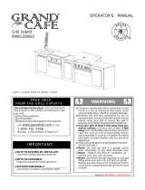
MAGNIFIED VIEW OF GRILL MAIN BURNER, INFRARED
BURNER FLAME THROUGH OPEN LID.
WARNING
!
!
Failure to comply with these instructions could result
in a fire or explosion that could cause serious bodily
injury, death or property damage.
Keep grill area clear and free from combustible mate-
rials, gasoline and other flammable vapors and liq-
uids.
Do not obstruct the flow of air for combustion and
ventilation.
Keep the ventilation openings of the tank enclosure
cabinet free and clear of debris.
Visually check burner flames occasionally to ensure
proper flame pattern as shown below.
/