


Contents
1 Safety
6
1.1 Warnings
6
2 Introduction
8
3 Installation
10
3.1 Mechanical Installation
10
3.2 Dimensions and Weights
11
4 Electrical Installation
13
4.1 Control Wiring
13
4.1.1 Ways to Control the Soft Starter 13
4.1.2 Control Terminals 13
4.1.3 Remote Inputs 13
4.1.4 Serial Communication 14
4.1.5 Ground Terminal 14
4.1.6 Power Terminations 15
4.2 Power Input and Output Congurations
16
4.2.1 Internally Bypassed Models (MCD5-0021B to MCD5-0961B) 16
4.2.2 MCD5-0245C 17
4.2.3 MCD5-0360C to MCD5-1600C 17
4.3 Motor Connection
17
4.3.1 Testing the Installation 17
4.3.2 In-line Installation 18
4.3.2.1 Internally Bypassed 18
4.3.2.2 Non-bypassed 18
4.3.2.3 Externally Bypassed 18
4.3.3 Inside Delta Installation 19
4.3.3.1 Internally Bypassed 19
4.3.3.2 Non-bypassed 19
4.3.3.3 Externally Bypassed 20
4.4 Current Ratings
20
4.4.1 In-line Connection (Bypassed) 21
4.4.2 In-line Connection (Non-bypassed/Continuous) 22
4.4.3 Inside Delta Connection (Bypassed) 23
4.4.4 Inside Delta Connection (Non-bypassed/Continuous) 24
4.5 Minimum and Maximum Current Settings
25
4.6 Bypass Contactor
26
4.7 Main Contactor
26
4.8 Circuit Breaker
26
Contents Operating Instructions
MG17K502 Danfoss A/S © 10/2015 All rights reserved. 1

4.9 Power Factor Correction
26
4.10 Fuses
26
4.10.1 Power Supply Fuses 26
4.10.2 Bussmann Fuses 27
4.10.3 Ferraz Fuses 29
4.10.4 UL Fuse Selection and Short Circuit Ratings 31
4.11 Schematic Diagrams
33
5 Product Features
35
5.1 Motor Overload Protection
35
5.2 Adaptive Control
35
5.3 Starting Modes
36
5.3.1 Constant Current 36
5.3.2 Current Ramp 36
5.3.3 Adaptive Control 36
5.3.4 Kick Start 37
5.4 Stopping Modes
37
5.4.1 Coast to Stop 37
5.4.2 TVR Soft Stop 37
5.4.3 Adaptive Control 38
5.4.4 Pump Stopping 38
5.4.5 Brake 38
5.5 Jog Operation
39
5.6 Inside Delta Operation
40
5.7 Typical Start Currents
41
5.8 Installation with Main Contactor
42
5.9 Installation with Bypass Contactor
43
5.10 Emergency Run Operation
44
5.11 Auxiliary Trip Circuit
45
5.12 DC Brake with External Zero-speed Sensor
46
5.13 Soft Braking
47
5.14 Two-speed Motor
48
6 Operation
50
6.1 Control Methods
50
6.2 Operation and LCP
51
6.2.1 Operating Modes 51
6.3 Remote Mounted LCP
52
6.3.1 Synchronising the LCP and the Soft Starter 52
6.4 Welcome Screen
52
6.5 Local Control Keys
52
Contents
VLT
®
Soft Starter MCD 500
2 Danfoss A/S © 10/2015 All rights reserved. MG17K502

6.6 Displays
52
6.6.1 Temperature Monitoring Screen (S1) 53
6.6.2 Programmable Screen (S2) 53
6.6.3 Average Current (S3) 53
6.6.4 Current Monitoring Screen (S4) 53
6.6.5 Frequency Monitoring Screen (S5) 53
6.6.6 Motor Power Screen (S6) 53
6.6.7 Last Start Information (S7) 53
6.6.8 Date and Time (S8) 53
6.6.9 SCR Conduction Bargraph 54
6.6.10 Performance Graphs 54
7 Programming
55
7.1 Access Control
55
7.2 Quick Menu
55
7.2.1 Quick Set-up 55
7.2.2 Application Set-up Examples 56
7.2.3 Loggings 57
7.3 Main Menu
57
7.3.1 Parameters 57
7.3.2 Parameter Shortcut 57
7.3.3 Parameter List 58
8 Parameter Descriptions
59
8.1 Primary Motor Settings
59
8.1.1 Brake 60
8.2 Protection
60
8.2.1 Current Imbalance 60
8.2.2 Undercurrent 61
8.2.3 Instantaneous Overcurrent 61
8.2.4 Frequency Trip 61
8.3 Inputs
62
8.4 Outputs
63
8.4.1 Relay A Delays 63
8.4.2 Relays B and C 63
8.4.3 Low Current Flag and High Current Flag 64
8.4.4 Motor Temperature Flag 64
8.4.5 Analog Output A 64
8.5 Start/Stop Timers
64
8.6 Auto-Reset
65
8.6.1 Auto-Reset Delay 65
Contents Operating Instructions
MG17K502 Danfoss A/S © 10/2015 All rights reserved. 3

8.7 Secondary Motor Set
65
8.8 Display
67
8.8.1 User Programmable Screen 67
8.8.2 Performance Graphs 68
8.9 Restricted Parameters
68
8.10 Protection Action
69
8.11 Factory Parameters
69
9 Tools
70
9.1 Set Date and Time
70
9.2 Load/Save Settings
70
9.3 Reset Thermal Model
70
9.4 Protection Simulation
71
9.5 Output Signal Simulation
71
9.6 Digital I/O State
71
9.7 Temp Sensors State
72
9.8 Alarm Log
72
9.8.1 Trip Log 72
9.8.2 Event Log 72
9.8.3 Counters 72
10 Troubleshooting
73
10.1 Trip Messages
73
10.2 General Faults
78
11 Specications
80
11.1 UL Compliant Installation
82
11.1.1 Models MCD5-0021B to MCD5-0105B 82
11.1.2 Models MCD5-0131B to MCD5-0215B 82
11.1.3 Models MCD5-0245B to MCD5-0396B 82
11.1.4 Models MCD5-0245C 82
11.1.5 Models MCD5-0360C to MCD5-1600C 82
11.1.6 Models MCD5-0469B to MCD5-0961B 82
11.1.7 Pressure Terminal/Connector Kits 82
11.2 Accessories
82
11.2.1 LCP Remote Mounting Kit 82
11.2.2 Communication Modules 82
11.2.3 PC Software 83
11.2.4 Finger Guard Kit 83
11.2.5 Surge Protection Kit (Lightning Protection) 83
12 Busbar Adjustment Procedure (MCD5-0360C to MCD5-1600C)
84
Contents
VLT
®
Soft Starter MCD 500
4 Danfoss A/S © 10/2015 All rights reserved. MG17K502


1 Safety
1.1 Warnings
When reading this manual, pay special attention to the
following symbols:
NOTICE
Useful hints for the reader.
CAUTION
Indicates a general warning.
WARNING
Indicates a high-voltage warning.
The examples and diagrams in this manual are included
solely for illustrative purposes. The information contained
in this manual is subject to change at any time and
without prior notice. Responsibility or liability is under no
circumstances accepted for direct, indirect, or
consequential damages resulting from the use or
application of this equipment.
NOTICE
Before changing any parameter settings, save the current
parameter to a le using MCD PC Software or the Save
User Set function.
WARNING
WARNING - ELECTRICAL SHOCK HAZARD
VLT
®
Soft Starters MCD 500 contain dangerous voltages
when connected to mains voltage. Only a competent
electrician should carry out the electrical installation.
Improper installation of the motor or the soft starter can
cause equipment failure, serious injury, or death. Follow
the guidelines in this manual and local electrical safety
codes.
Models MCD5-0360C ~ MCD5-1600C:
Treat the bus bar and heat sink as live whenever the unit
has mains voltage connected (including when the soft
starter is tripped or waiting for a command).
WARNING
Disconnect the soft starter from mains voltage before
carrying out repair work.
It is the responsibility of the person installing the soft
starter to provide proper grounding and branch circuit
protection according to local electrical safety codes.
Do not connect power factor correction capacitors to the
output of MCD 500 soft starters. If static power factor
correction is employed, it must be connected to the
supply side of the soft starter.
MCD5-0021B ~ MCD5-961B:
After transportation, mechanical shock, or rough
handling there is a risk that the bypass contactor has
latched into the On state. To prevent the motor from
starting immediately, on rst commissioning, or
operation after transportation, always ensure that the
control supply is applied before the power. Applying
control supply before power ensures that the contactor
state is initialised.
WARNING
SAFETY OF PERSONNEL
The soft starter is not a safety device and does not
provide electrical isolation or disconnection from the
supply.
•
If isolation is required, the soft starter must be
installed with a main contactor.
•
The start and stop functions of the soft starter
must not be relied upon for personnel safety.
Faults occurring in the mains supply, the motor
connection, or the electronics of the soft starter,
can cause unintended motor starts or stops.
To provide machine or personnel safety, control the
isolation device through an external safety system.
In Auto On mode, the motor can be controlled remotely
(via remote inputs) while the soft starter is connected to
mains.
CAUTION
These stop functions are not sucient to avoid
unintended start.
If faults occur in the electronics of the soft starter, a
motor that has been stopped may start. A temporary
fault in the supply mains or a cease in the motor
connection can also cause a stopped motor to start.
Safety
VLT
®
Soft Starter MCD 500
6 Danfoss A/S © 10/2015 All rights reserved. MG17K502
11

CAUTION
Use the Auto start feature with caution. Read all the
notes related to Auto start before operation.
Equipment containing electrical
components may not be disposed of
together with domestic waste.
It must be collected separately as
electrical and electronic waste
according to local and currently valid
legislation.
Table 1.1 Disposal Instructions
Safety Operating Instructions
MG17K502 Danfoss A/S © 10/2015 All rights reserved. 7
1 1

2 Introduction
The VLT
®
Soft Starter MCD 500 is an advanced digital soft
start solution for motors 11–850 kW. The soft starters
provide a complete range of motor and system protection
features, and are designed for reliable performance in the
most demanding installation situations.
2.1.1 Feature List
Models for all connection requirements
•
21–1600 A (in-line connection).
•
In-line or inside delta connection.
•
Internally bypassed up to 961 A.
•
Mains voltage: 200–525 V AC or 380–690 V AC.
•
Control voltage: 24 V AC/V DC, 110–120 V AC, or
220–240 V AC.
User-friendly LCP
•
Loggings.
•
Real-time graphs.
•
SCR conduction bar graph.
Tools
•
Application set-ups.
•
Date and time stamped event log with 99 entries.
•
8 most recent trips.
•
Counters.
•
Protection simulation.
•
Output signal simulation.
Inputs and outputs
•
Local or remote control input options.
(3 x xed, 1 x programmable).
•
Relay outputs (3 x programmable).
•
Analog programmable output.
•
24 V DC 200 mA supply output.
Start and run modes
•
Adaptive control.
•
Constant current.
•
Current ramp.
•
Kick start.
•
Jog.
•
Emergency run operation.
Stop modes
•
Adaptive deceleration control.
•
Timed voltage ramp soft stop.
•
DC brake.
•
Soft brake.
•
Starter disable.
Other features
•
Auto start/stop timer.
•
Second order thermal model.
•
Battery back-up of clock and thermal model.
•
Optional DeviceNet, Modbus, Ethernet, or
PROFIBUS communication modules.
Comprehensive protection
•
Wiring/Connection/Supply
- Motor connection.
- Phase sequence.
- Power loss.
- Individual phase loss.
- Mains frequency.
•
Current
- Excess start time.
- Current imbalance.
- Undercurrent.
- Instantaneous overcurrent.
•
Thermal
- Motor thermistor.
- Motor overload.
- Bypass contactor overload.
- Heat sink temperature.
•
Communication
- Network comms.
- Starter comms.
•
External
- Input trip.
•
Starter
- Individually short-circuited SCR.
- Battery/clock.
Introduction
VLT
®
Soft Starter MCD 500
8 Danfoss A/S © 10/2015 All rights reserved. MG17K502
22

2.1.2 Type Code
MCD 5
- -
-
-
0021 = 21 A, AC53b 3-30:330
0037 = 37 A, AC53b 3-30:330
0043 = 43 A, AC53b 3-30:330
0053 = 53 A, AC53b 3-30:330
0068 = 68 A, AC53b 3-30:570
0084 = 84 A, AC53b 3-30:570
0089 = 89 A, AC53b 3-30:570
0105 = 105 A, AC53b 3-30:570
0131 = 131 A, AC53b 3-30:570
0141 = 141 A, AC53b 3-30:570
0195 = 195 A, AC53b 3-30:570
0215 = 215 A, AC53b 3-30:570
0245 = 245 A, AC53b 3-30:570
0331 = 331 A, AC53b 3-30:570
0396 = 396 A, AC53b 3-30:570
0469 = 469 A, AC53b 3-30:570
0525 = 525 A, AC53b 3-30:570
0632 = 632 A, AC53b 3-30:570
0744 = 744 A, AC53b 3-30:570
0826 = 826 A, AC53b 3-30:570
0961 = 961 A, AC53b 3-30:570
00 = IP00
20 = IP20
G1 = 0021 ~ 0105 A
G2 = 0131 ~ 0215 A
G3 = 0245 ~ 0396 A
G4 = 0360 ~ 0961 A
G5 = 1200 ~ 1600 A
0245 = 245 A, AC53a 3-30:50-6
0360 = 360 A, AC53a 3-30:50-6
0380 = 380 A, AC53a 3-30:50-6
0428 = 428 A, AC53a 3-30:50-6
0595 = 595 A, AC53a 3-30:50-6
0619 = 619 A, AC53a 3-30:50-6
0790 = 790 A, AC53a 3-30:50-6
0927 = 927 A,AC53a 3-30:50-6
1200 = 1200 A, AC53a 3-30:50-6
1410 = 1410 A, AC53a 3-30:50-6
1600 = 1600 A, AC53a 3-30:50-6
177HA382.11
Current rating
B = Bypassed
C = Non-bypassed
Mains voltage
T5 = 200 - 525 VAC
T7 = 380 - 690 VAC
Frame size
= Not selectable
Not used
IP rating
Control voltage
CV1 = 24 VAC/VDC
CV2 = 110-120 VAC or 220-240 VAC
Illustration 2.1 Type Code Ordering Form
Introduction Operating Instructions
MG17K502 Danfoss A/S © 10/2015 All rights reserved. 9
2 2

3 Installation
3.1 Mechanical Installation
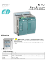
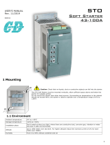
1 MCD5-0021B to MCD5-0215B: Allow 100 mm (3.94 inches) between the soft starters.
MCD5-0245B to MCD5-0961B: Allow 200 mm (7.88 inches) between the soft starters.
MCD5-0245C: Allow 100 mm (3.94 inches) between the soft starters.
MCD5-0360C to MCD5-1600C: Allow 200 mm (7.88 inches) between the soft starters.
2 MCD5-0021B to MCD5-0215B: Allow 50 mm (1.97 inches) between the soft starter and solid surfaces.
MCD5-0245B to MCD5-0961B: Allow 200 mm (7.88 inches) between soft starters.
MCD5-0245C: Allow 100 mm (3.94 inches) between the soft starter and solid surfaces.
MCD5-0360C to MCD5-1600C: Allow 200 mm (7.88 inches) between the soft starter and solid surfaces.
3 It is possible to mount the soft starter on its side. Derate the soft starter rated current by 15%.
4 If mounted without communication modules, soft starters may be mounted side-by-side with no clearance.
Illustration 3.1 Clearances and Derating Values at Installation
Installation
VLT
®
Soft Starter MCD 500
10 Danfoss A/S © 10/2015 All rights reserved. MG17K502
33

3.2 Dimensions and Weights
177HA514.10
Model A [mm] (in) B [mm] (in) C [mm] (in) D [mm] (in) E [mm] (in) Weight [kg] (lbs)
MCD5-0021B
295
(11.6)
278
(10.9)
150
(5.9)
124
(4.9)
183
(7.2)
4.2
(9.3)
MCD5-0037B
MCD5-0043B
MCD5-0053B
MCD5-0068B
213
(8.14)
4.5
(9.9)
MCD5-0084B
4.9
(10.8)
MCD5-0089B
MCD5-0105B
MCD5-0131B
438
(17.2)
380
(15.0)
275
(10.8)
248
(9.8)
250
(9.8)
14.9
(32.8)
MCD5-0141B
MCD5-0195B
MCD5-0215B
MCD5-0245B
440
(17.3)
392
(15.4)
424
(16.7)
376
(14.8)
296
(11.7)
26 (57.2)
MCD5-0331B
30.2
(66.6)
MCD5-0396B
MCD5-0469B
640
(25.2)
600
(23.6)
433
(17.0)
320
(12.6)
295
(11.6)
49.5
(109.1)
MCD5-0525B
MCD5-0632B
60.0
(132.3)
MCD5-0744B
MCD5-0826B
MCD5-0961B
MCD5-0245C
460
(18.1)
400
(15.0)
390
(15.4)
320
(12.6)
279
(11.0)
23.9
(52.7)
MCD5-0360C
689
(27.1)
522
(20.5)
430
(16.9)
320
(12.6)
300
(11.8)
35
(77.2)
MCD5-0380C
MCD5-0428C
MCD5-0595C
45
(99.2)
MCD5-0619C
MCD5-0790C
MCD5-0927C
Installation Operating Instructions
MG17K502 Danfoss A/S © 10/2015 All rights reserved. 11
3 3

Model A [mm] (in) B [mm] (in) C [mm] (in) D [mm] (in) E [mm] (in) Weight [kg] (lbs)
MCD5-1200C
856
(33.7)
727
(28.6)
585
(23.0)
500
(19.7)
364
(14.3)
120
(264.6)
MCD5-1410C
MCD5-1600C
Illustration 3.2 Dimensions and Weights
Installation
VLT
®
Soft Starter MCD 500
12 Danfoss A/S © 10/2015 All rights reserved. MG17K502
33

4 Electrical Installation
4.1 Control Wiring
4.1.1 Ways to Control the Soft Starter
Control the soft starter in 3 ways:
•
Pressing the keys on the LCP.
•
Via remote inputs.
•
Via a serial communication link.
The MCD 500 always responds to a local start or stop
command (via the [Hand On] and [O] keys on the LCP).
Pressing the [Auto On] key selects remote control (the soft
starter accepts commands from the remote inputs). In
remote mode, the Auto On LED is on. In local mode, the
Hand On LED is on if the soft starter starts or runs. The O
LED is on if the soft starter is stopped or stops.
4.1.2 Control Terminals
Control terminations use 2.5 mm
2
plug-in terminal blocks.
Dierent models require control voltage to dierent
terminals:
•
CV1 (24 V AC/V DC): A5, A6.
•
CV2 (110–120 V AC): A5, A6.
•
CV2 (220–240 V AC): A4, A6.
Illustration 4.1 Wiring to Control Terminals
NOTICE
Do not short terminals 05 and 06 without using a
thermistor.
All control terminals and relay terminals comply with SELV
(Safety Extra Low Voltage). This protection does not apply
to grounded delta leg above 400 V.
To maintain SELV, all connections made to the control
terminals must be PELV (for example thermistor must be
reinforced/double insulated from motor).
NOTICE
SELV oers protection by way of extra low voltage.
Protection against electric shock is ensured when the
electrical supply itself is of the SELV type and the instal-
lation follows local/national regulations on SELV supplies.
NOTICE
Galvanic (ensured) isolation is obtained by fullling
requirements for higher isolation and by providing the
relevant creepages/clearance distances. These
requirements are described in the IEC 61140 standard.
The components that make up the electrical isolation
also comply with the requirements for higher isolation
and the relevant test as described in IEC 61140.
4.1.3 Remote Inputs
The soft starter has 3 xed inputs for remote control.
Control these inputs by contacts rated for low voltage, low
current operation (gold ash or similar).
177HA504.10
Start/stop
Reset
Start
Stop
Reset
Start
Stop
Reset
15
16
17
18
25
18
15
16
17
18
25
18
15
16
17
18
25
18
2
3
1
1 2-wire control
2 3-wire control
3 4-wire control
Illustration 4.2 2-, 3-, and 4-wire Control
The reset input can be normally open or normally closed.
To select the conguration, use parameter 3-8 Remote Reset
Logic.
CAUTION
Do not apply voltage to the control input terminals.
These terminals are active 24 V DC inputs and must be
controlled with potential-free contacts.
Segregate cables to the control inputs from mains
voltage and motor cabling.
Electrical Installation Operating Instructions
MG17K502 Danfoss A/S © 10/2015 All rights reserved. 13
4 4

4.1.4 Serial Communication
Control via the serial communication network is always
enabled in local control mode and can be enabled or
disabled in remote control mode (see parameter 3-2
Comms in Remote). Control via the serial communication
network requires an optional communication module.
4.1.5 Ground Terminal
Ground terminals are located at the back of the soft
starter.
•
MCD5-0021B to MCD5-0105B have 1 terminal on
the input side (top).
•
MCD5-0131B to MCD5-0961B and MCD5-0245C to
MCD5-1600C have 2 terminals, 1 on the input
side (top), and 1 on the output side (bottom).
Electrical Installation
VLT
®
Soft Starter MCD 500
14 Danfoss A/S © 10/2015 All rights reserved. MG17K502
44

4.1.6 Power Terminations
NOTICE
For personnel safety, snap-o tabs protect the power terminals on models up to MCD5-0105B. When using large cables,
it may be necessary to break o these tabs.
NOTICE
Some units use aluminium busbars. When connecting power terminations, clean the surface contact area thoroughly
(using an emery or stainless steel brush), and use an appropriate jointing compound to prevent corrosion.
Use only copper stranded or solid conductors, rated for 75 °C or higher.
177HA646.10
Cable size: 6–50 mm
2
(AWG 10-1/0)
Torque: 4 Nm (2.9 ft-lb)
177HA647.10
14 mm (0.55 inch)
177HA648.10
Torx T20 x 150
177HA649.10
Flat 7 mm x 150
MCD5-0021B to MCD5-0105B
38 Nm (28 ft-lb)
5 mm
15 mm
28 mm
11 mm
(M10)
177HA643.10
MCD5-0131B MCD5-0141B to MCD5-0215B MCD5-0245B
38 Nm (28 ft-lb) 38 Nm (28 ft-lb)
6 mm
15 mm
28 mm
11 mm
(M10)
177HA644.10
13 mm
12 mm
32 mm
11 mm
(M10)
177HA645.10
MCD5-0331B to MCD5-0396B MCD5-0469B to MCD5-0961B MCD5-0245C
MCD5-0360C to MCD5-0927C MCD5-1200C to MCD5-1600C
Table 4.1 Measurements and Torques for Power Terminations
Electrical Installation Operating Instructions
MG17K502 Danfoss A/S © 10/2015 All rights reserved. 15
4 4

4.2 Power Input and Output Congurations
4.2.1 Internally Bypassed Models (MCD5-0021B to MCD5-0961B)
Models MCD5-0021B to MCD5-0215B have power inputs at the top of the unit and outputs at the bottom of the unit.
Internally bypassed models MCD5-0245B to MCD5-0396B have output busbars at the bottom of the unit and input busbars
at both the top and bottom. The AC supply can be connected top-in, bottom-out or bottom-in, bottom-out.
Internally bypassed models MCD5-0469B to MCD5-0961B have input and output busbars at the top and bottom of the unit.
The AC supply can be connected:
•
Top-in/bottom-out.
•
Top-in/top-out.
•
Bottom-in/bottom-out.
•
Bottom-in/top-out.
20.0
1/L1, 3/L2, 5/L3
2/T1, 4/T2, 6/T3
1/L1 3/L2 5/L3
2/T1 4/T2 6/T3
1/L1 3/L2 5/L3
2/T1 4/T2 6/T3
1/L1 3/L2 5/L3
2/T1 4/T2 6/T3
1/L1 3/L2 5/L3
1/L1 3/L2 5/L3
2/T1 4/T2 6/T3
177HA650.10
Illustration 4.3 Internally Bypassed Models, MCD5-0021B to MCD5-0105B, MCD5-0131B to MCD5-0215B, MCD5-0245B to MCD5-0396B,
MCD5-0469B to MCD5-0961B
Electrical Installation
VLT
®
Soft Starter MCD 500
16 Danfoss A/S © 10/2015 All rights reserved. MG17K502
44

4.2.2 MCD5-0245C
MCD5-0245C has dedicated bypass terminals at the bottom
of the unit. The bypass terminals are:
•
T1B
•
T2B
•
T3B
177HA651.10
1/L1 3/L2 5/L3
T1B T2B T3B
2/T1 4/T2 6/T3
Illustration 4.4 Bypass Terminals on MCD5-0245C
4.2.3 MCD5-0360C to MCD5-1600C
MCD5-0360C to MCD5-1600C have dedicated bypass
terminals on the input busbars. The bypass terminals are:
•
L1B
•
L2B
•
L3B
The busbars on non-bypassed models MCD5-0360C to
MCD5-1600C can be adjusted for top or bottom input and
output as required. See chapter 12 Busbar Adjustment
Procedure (MCD5-0360C to MCD5-1600C) for step-by-step
instructions. The soft starters are manufactured top-in/
bottom-out.
NOTICE
For models MCD5-0360C to MCD5-1600C to be UL-
compliant, mount them top-in, bottom-out, or top-out,
bottom-in. See chapter 11.1 UL Compliant Installation for
more information.
(L1B L2B L3B)
1/L1 3/L2 5/L3
2/T1 4/T2 6/T3
1/L1 3/L2 5/L3
(L1B L2B L3B)
2/T1 4/T2 6/T3
(L1B L2B L3B)
1/L1 3/L2 5/L3
2/T1 4/T2 6/T3
1/L1 3/L2 5/L3
(L1B L2B L3B)
2/T1 4/T2 6/T3
177HA652.10
Illustration 4.5 Location of Bypass Terminals, MCD5-0360C to
MCD5-1600C
4.3 Motor Connection
MCD 500 soft starters can be connected to the motor in-
line or inside delta (also called 3-wire and 6-wire
connection). When connecting in inside delta, enter the
motor full load current (FLC) for parameter 1-1 Motor Full
Load Current. The MCD 500 automatically calculates inside
delta current based on this data. Parameter 15-7 Motor
Connection is set to Auto Detect as default and can be set
to force the soft starter in inside delta or in-line.
4.3.1 Testing the Installation
The MCD 500 can be connected to a small motor for
testing. During this test, the control input and relay output
protection settings can be tested. This test mode is not
suitable for testing soft starting or soft stopping
performance.
The minimum FLC of the test motor is 2% of the minimum
FLC of the soft starter (see chapter 4.5 Minimum and
Maximum Current Settings).
NOTICE
When testing the soft starter with a small motor, set
parameter 1-1 Motor FLC to the minimum allowable
value.
Models which are internally bypassed do not require an
external bypass contactor.
Electrical Installation Operating Instructions
MG17K502 Danfoss A/S © 10/2015 All rights reserved. 17
4 4

4.3.2 In-line Installation
4.3.2.1 Internally Bypassed
177HA430.12
M
3
6/T3
2/T1
5/L3
3/L2
1/L1
13
14
4/T2
E
K1
K1 F1
K1 Main contactor (optional)
F1 Semiconductor fuses (optional)
Illustration 4.6 In-line Installation, Internally Bypassed
4.3.2.2 Non-bypassed
177HA429.12
6/T3
2/T1
5/L3
3/L2
1/L1
13
14
4/T2
E
K1
K1 F1
M
3
K1 Main contactor (optional)
F1 Semiconductor fuses (optional)
Illustration 4.7 In-line Installation, Non-bypassed
4.3.2.3 Externally Bypassed
Non-bypassed models have dedicated bypass terminals,
which allow the soft starter to continue providing
protection and monitoring functions even when bypassed
via an external contactor. Connect the bypass contactor to
the bypass terminals and control it by a programmable
output congured to Run (see parameters 4-1 to 4-9).
NOTICE
The bypass terminals on MCD5-0245C are:
•
T1B
•
T2B
•
T3B
The bypass terminals on MCD5-0360C to MCD5-1600C
are:
•
L1B
•
L2B
•
L3B
If necessary, the fuses can be installed on the input side.
177HA617.11
M
3
F1
6/T3
2/T1
5/L3
3/L2
1/L1
13
14
4/T2
E
K1
K1
T1B
T2B
T3B
K2
34
33
K2
K1 Main contactor
K2 Bypass contactor (external)
F1 Semiconductor fuses (optional)
Illustration 4.8 In-line Installation, Externally Bypassed,
MCD5-0245C
Electrical Installation
VLT
®
Soft Starter MCD 500
18 Danfoss A/S © 10/2015 All rights reserved. MG17K502
44
Page is loading ...
Page is loading ...
Page is loading ...
Page is loading ...
Page is loading ...
Page is loading ...
Page is loading ...
Page is loading ...
Page is loading ...
Page is loading ...
Page is loading ...
Page is loading ...
Page is loading ...
Page is loading ...
Page is loading ...
Page is loading ...
Page is loading ...
Page is loading ...
Page is loading ...
Page is loading ...
Page is loading ...
Page is loading ...
Page is loading ...
Page is loading ...
Page is loading ...
Page is loading ...
Page is loading ...
Page is loading ...
Page is loading ...
Page is loading ...
Page is loading ...
Page is loading ...
Page is loading ...
Page is loading ...
Page is loading ...
Page is loading ...
Page is loading ...
Page is loading ...
Page is loading ...
Page is loading ...
Page is loading ...
Page is loading ...
Page is loading ...
Page is loading ...
Page is loading ...
Page is loading ...
Page is loading ...
Page is loading ...
Page is loading ...
Page is loading ...
Page is loading ...
Page is loading ...
Page is loading ...
Page is loading ...
Page is loading ...
Page is loading ...
Page is loading ...
Page is loading ...
Page is loading ...
Page is loading ...
Page is loading ...
Page is loading ...
Page is loading ...
Page is loading ...
Page is loading ...
Page is loading ...
Page is loading ...
Page is loading ...
Page is loading ...
Page is loading ...
Page is loading ...
Page is loading ...
Page is loading ...
Page is loading ...
-
 1
1
-
 2
2
-
 3
3
-
 4
4
-
 5
5
-
 6
6
-
 7
7
-
 8
8
-
 9
9
-
 10
10
-
 11
11
-
 12
12
-
 13
13
-
 14
14
-
 15
15
-
 16
16
-
 17
17
-
 18
18
-
 19
19
-
 20
20
-
 21
21
-
 22
22
-
 23
23
-
 24
24
-
 25
25
-
 26
26
-
 27
27
-
 28
28
-
 29
29
-
 30
30
-
 31
31
-
 32
32
-
 33
33
-
 34
34
-
 35
35
-
 36
36
-
 37
37
-
 38
38
-
 39
39
-
 40
40
-
 41
41
-
 42
42
-
 43
43
-
 44
44
-
 45
45
-
 46
46
-
 47
47
-
 48
48
-
 49
49
-
 50
50
-
 51
51
-
 52
52
-
 53
53
-
 54
54
-
 55
55
-
 56
56
-
 57
57
-
 58
58
-
 59
59
-
 60
60
-
 61
61
-
 62
62
-
 63
63
-
 64
64
-
 65
65
-
 66
66
-
 67
67
-
 68
68
-
 69
69
-
 70
70
-
 71
71
-
 72
72
-
 73
73
-
 74
74
-
 75
75
-
 76
76
-
 77
77
-
 78
78
-
 79
79
-
 80
80
-
 81
81
-
 82
82
-
 83
83
-
 84
84
-
 85
85
-
 86
86
-
 87
87
-
 88
88
-
 89
89
-
 90
90
-
 91
91
-
 92
92
-
 93
93
-
 94
94


Danfoss VLT® Soft Starter MCD 500 Operating instructions
- Type
- Operating instructions
- This manual is also suitable for
Ask a question and I''ll find the answer in the document
Finding information in a document is now easier with AI
Related papers
-
Danfoss VLT Soft Starter MCD 500 User guide
-
-
-
-
-
-
-
-
Danfoss VLT Soft Starter MCD 100 User guide
-
Other documents
-
 Magnetek RVS-DX-310-E User manual
-
Motorola Symbol MC9002 User manual
-
Toshiba VF010H05 User manual
-
-
-
Hubbell LXi-1100 User manual
-
 CD Automation Soft Starter Owner's manual
-
Fellowes DS-1200CS Owner's manual
-
 CD Automation Soft Starter Owner's manual
-
Fellowes DS-1200C User manual


