Page is loading ...

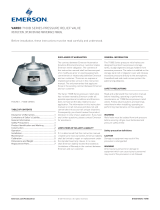
ANDERSON GREENWOOD MARVAC FIGURE 785S EMERGENCY RELIEF MANHOLE
InstallatIon and MaIntenance InstructIons
SAFETY PRECAUTIONS
Read and understand this instruction manual
before installing, operating or performing
maintenance on a Figure 785S emergency relief
manhole. Follow all precautions and warnings
noted herein when installing, operating or
performing maintenance on this equipment.
Safety precaution definitions
CAUTION
Damage to equipment may result if this
precaution is disregarded.
WARNING
Direct injury to personnel or damage to
equipment that can cause injury to personnel may
result if this precaution is not followed.
NOTE
This manual is issued for guidance only and does not
affect our standard terms and conditions and our
product limited warranty, all of which are available
upon request.
1 INSTALLATION
785S emergency relief manholes must be
mated with the appropriate flange.
1. These valves must be gasketed and bolted
to a flat machined horizontal flange, bolts
are to be tightened uniformly to ensure a
good seal.
2. The pressure on these valves is controlled
by compression springs, which are adjusted
and set at works before dispatch.
3. This valve does not contain any internal
packing. Therefore, internal checks should
not be necessary.
4. It is recommended that carbon steel valves
be given a coat of paint immediately after
installation is complete. Apply paint to
external surfaces only.
WARNING
Relief vents must be isolated from tank pressure
before servicing. All gas must be blocked and
pressure vented safely.
Wear appropriate gloves and/or breathing
apparatus if hazardous vapors are present.
2 MAINTENANCE
(during atmospheric venting period)
Before installation these instructions must be read fully and understood
© 2017 Emerson. All Rights Reserved.Emerson.com/FinalControl VCIOM-01937-EN 18/02
Refer to Figure 1
1. Note exact position (height) of top spring
washer (item 7).
2. Remove locknuts (item 6) and unscrew nuts
(item 5) remove spring washers (item 7) and
springs.
3. Inspect O-rings (item 3) for damage and
replace if necessary.
4. Re-assemble in reverse order.
5. Reset top spring washer to its original
position (height), tighten locknuts.
6. Check pressure relief setting on test run
and adjust if necessary.
7. Ensure when adjusting springs that there
is a maximum height tolerance of ± 2mm
between each of the spring arrangements.
NOTE
The efficiency of the valve depends on maintaining
good seating surfaces. Therefore, maintenance
periods should be adjusted to suit service conditions.

2
ANDERSON GREENWOOD MARVAC FIGURE 785S EMERGENCY RELIEF MANHOLE
InstallatIon and MaIntenance InstructIons
3 SPARES
When spare parts are required, the customer
should quote the valve size, serial number,
the item number and the material of the parts
required.
The valve size and serial number can be
obtained from the valve identification label. The
item number and description can be obtained
from the arrangement (left).
Recommended spares
Item 3 O-rings
PARTS LIST
Item Description CS specification SS specification
1 Base C. Steel 316 SS
2 Cover plate C. Steel 316 SS
3 Seal Nitrile Nitrile
4 Spring 316 SS 316 SS
5 Nut 316 SS 316 SS
6 Lock nut 316 SS 316 SS
7 Spring washer 316 SS 316 SS
8 Bearing 316 SS 316 SS
9 Bush Nylatron Nylatron
10 Screws 316 SS 316 SS
FIGURE 1 - TYPICAL ASSEMBLY
Neither Emerson, Emerson Automation Solutions, nor any of their affiliated entities assumes responsibility for the selection, use or maintenance of any product.
Responsibility for proper selection, use, and maintenance of any product remains solely with the purchaser and end user.
Anderson Greenwood is a mark owned by one of the companies in the Emerson Automation Solutions business unit of Emerson Electric Co. Emerson Automation
Solutions, Emerson and the Emerson logo are trademarks and service marks of Emerson Electric Co. All other marks are the property of their respective owners.
The contents of this publication are presented for informational purposes only, and while every effort has been made to ensure their accuracy, they are not to be
construed as warranties or guarantees, express or implied, regarding the products or services described herein or their use or applicability. All sales are governed by
our terms and conditions, which are available upon request. We reserve the right to modify or improve the designs or specifications of such products at any time without
notice.
Emerson.com/FinalControl
/