Keystone Butterfly valves Figure 55 Owner's manual
- Type
- Owner's manual

KEYSTONE BUTTERFLY VALVES FIGURE 55
INSTALLATION AND MAINTENANCE INSTRUCTIONS
1 STORAGE AND HANDLING
1.1 Protection
Keystone butterfly valves are delivered with
protection in accordance with the Keystone
Engineering Instructions, to protect the valve
seats and disc from damage. Wrapping and/or
covers should be left in place until immediately
before fitting to the pipe.
1.2 Storage
When valves are to be stored for some time
(2months or more) before being fitted, storage
should be in the original delivery crates or cases.
1.2.1 Storage conditions
The valves should be stored off the
ground in a clean, dry indoor area.
Protect the valve from temperature
and humidity extremes, and exposure
to excessive dust, moisture, vibration,
deformations, sunlight and ozone.
Please read these instructions carefully
Hazard potentials:
• disregarding of instructions
• improper use of product
• insufficiently qualified personnel
Valve application to be within the
pressure/temperature limits indicated in
theP/T diagram.
Essential points and functions of the valve
should be inspected on a regular basis.
When the valve is used in an end-of-line
function, PED Cat-I applications are allowed
only. For other categories, contact factory.
Emerson.com/FinalControl
1.3 Handling
1.3.1 Packed valves
Lifting and handling of the packed valves in
crates should be carried out by appropriate
lifting equipment. If a fork lift truck is used,
appropriate fork hitches are required.
The lifting and handling of packed valves in
cases will be carried out in the lifting points.
The transportation of all packed material
should be carried out safely and
according the local safety regulations.
1.3.2 Unpacked valves
The lifting and the handling of these
valves has to be carried out by using
appropriate means and by respecting
the carrying limits. The handling must,
preferably, be carried out on pallets,
protecting the machined surfaces and
seat to avoid damage.
When lifting the large dimension valves,
the sling and the hooking of the load must
be carried out by using the appropriate
tools (brackets, hook, fasteners) and load
balancing tools in order to prevent the
valves from falling or moving during the
lifting and handling.
The valve may be lifted only by slings
attached to the flange holes or valve body;
never to the actuator or the valve opening.
VCIOM-00756-EN 19/01© 2017 Emerson. All Rights Reserved.
Before installation these instructions must be fully read and understood
Recommendations
1. Temperature: storage temperature below
25°C, above 0°C preferable below 15°C.
2. Humidity: storage conditions should be such
that condensation does not occur, store in
a dry environment. Maximal 50% relative
humidity.
3. Light: valve rubbers should be protected
from light, in particular direct sunlight or
strong artificial light with high ultra violet.
4. Ozone: storage rooms should not
contain any equipment generating ozone.
E.g.lamps, electric motors.
IMPORTANT
Before valves are being installed or used the
following actions are recommended.
1. Valves/parts have to be inspected and
thoroughly cleaned if required.
2. Rubber parts need to be greased with silicone
grease if not present anymore.
3. All surfaces in contact with seats have to be
thoroughly cleaned and greased with silicone
grease if stored for more than 5 months.

2
KEYSTONE BUTTERFLY VALVES FIGURE 55
INSTALLATION AND MAINTENANCE INSTRUCTIONS
YY
D max./min.
Q
2.1 Valve inspection
1. Carefully remove the valve from the
shipping package (box or pallet) avoiding any
damage to the valve or, in case of automated
valves, to the electric or pneumatic/
hydraulic actuator or instrumentation.
2. Confirm that the materials of construction
listed on the valve nameplate are
appropriate for the service intended and are
as specified.
3. It is not allowed to use third party spare
parts. In case of third party spare parts, safe
operation is not guaranteed.
2 INSTALLATION
WARNING
For safety reasons, it is important to take the
following precautions before you start work on
the valve:
1. Personnel making any adjustments to the
valves should utilize suitable equipment. All
required personal protection means should be
worn.
2. The line must be depressurized before
installing the valve.
3. Personnel trained in all aspects of manual and
mechanical handling techniques only must
carry out handling of the valves.
4. Misuse of the valve is not allowed. For
example: the valve, handles, actuators or other
parts may not be used as ‘climbing tools’.
5.
Ensure that valve pressure/temperature
limitations marked on the identification tag are
within the service conditions. The trim number
on the valve’s tagplate identifies the valve
materials. See Product Manual for valve specific
P/T diagram and trim number definition.
6. Ensure that valve materials are compatible
with the pipeline fluid.
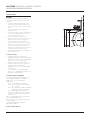
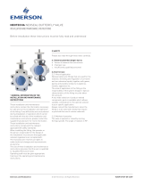
2.2 Flange and pipe compatibility
Check matching of flange drilling pattern of
valve and pipe flange before assembly.
Flanges have to meet the following
requirements:
- The face inside diameter should be:
D min.:
The valve Q-dimension + adequate
disc clearance.
D max.:
The inside diameter (ID) of standard
pipe for the nominal size ISO4200.
- If the flange (or pipe) is provided with a
raised face, the diameter of this shall be at
least 10mm larger than the YY-dimension
of the valve.
The use of the flange-gaskets is not allowed
since it might damage the valve.
The Keystone seat-face design eliminates the
need for the gaskets.
Use flange bolting in agreement with
appropriate standard.
Do not use flange gaskets!

3
2.3 Valve installation
The valves are bi-directional and may be fitted
in either direction relative to the flow. The valve
will control flow equally in either direction.
Therecommended installation position is shaft
horizontal and the lower disc edge opening
down-stream. (Especially for slurry service and
media with a tendency for sedimentation). For
optimum valve control and smooth performance,
it is recommended to have a 10 to 20 pipe
diameters of straight run inlet piping and 3 to 5
pipe diameters straight outlet piping. A valve is
no crow-bar. Do not use the valve to spread the
flanges. Seat damage might be the result.
2.3.1 Existing system (see sketch)
1. Check whether the flange distance
meets the valve face-to-face
dimensions. Spread with adequate
tooling the flanges for easy insertion of
the valve.
2. Close the valve so far, that the disc
edge is at least 10mm within the body.
3. Insert the valve between the flanges,
center the valve body and insert all
flange bolts.
4. Maintain the valve flange alignment
while gradually removing the flange-
spreaders and tighten the flange-bolts
hand tight.
5. Slowly open and close the valve to
check for adequate disc clearance.
6. Cross-tighten all bolting to the proper
torque.
2.3.2 New system (see sketch)
1. With the disc in near-closed position
center each mating flange with the
valve body. Fix the body with some
flange-bolts and tighten the bolts.
2. Use the flange-valve-flange assembly
for fit-up and centering to the pipe.
3. Tack-weld the flanges to the pipe.
4. Remove the bolting and the valve from
between the flanges.
KEYSTONE BUTTERFLY VALVES FIGURE 55
INSTALLATION AND MAINTENANCE INSTRUCTIONS
NOTES
- The valve can be installed in the pipe-line either with
or without the actuator mounted on top of the valve.
Make sure that you can turn the disc cautious so you
can feel a mismatch resulting from a disc touching
the adjacent piping.
- Do not use the valve as a support of the pipe line
construction.
- Adjacent piping must be positioned so that minimal
piping stresses are transmitted to the valve flanges
during or after installation.
- Handling and lifting of the valves during installation
MUST be performed following the same instructions
described in previous paragraph ‘1.3 Handling’.
IMPORTANT
Mating flange faces should be in good condition
and free of dirt and/or inclusions. Both pipe
insides to be well cleaned.
IMPORTANT
Do not finish-weld the flanges to the pipe with the
valve bolted between the flanges as this will result
in serious heat-damage to the seat.
5. Finish-weld the flanges to the pipe and
allow the flanges to cool completely.
6. Install the valve now according to the
procedure for installing in existing
systems.

4
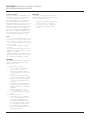
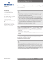
EXISTING SYSTEM NEW SYSTEM
1. Spread the flanges with the adequate tooling.
Insertsome flange bolts to bear the valve.
1. Center a flange-valve-flange assembly
between the pipes.
2. Open the valve and remove the flange spreads 2. Tack weld the flanges to the pipes.
3. Close the valve clockwise, return to open position
and cross-tighten all bolting.
3. R
emove the valve and finish weld. Install the valve
according to the procedure in the left column.
2.4 Valve verification
Check the operation of the valve by operating it
to ‘full open’ and ‘full close’. To verify the valve
operation, the disc position indicator on the
actuator or the handle should rotate between
the ‘full open’ and ‘full close’ indicators on the
actuator or throttle plate. Generally the valve
disc travels clockwise to close.
KEYSTONE BUTTERFLY VALVES FIGURE 55
INSTALLATION AND MAINTENANCE INSTRUCTIONS
2.5 Sources of possible danger
This section contains some examples of
possible foreseen danger sources.
2.5.1 Mechanical
A. When manual operators are used,
available space should be checked in
order to avoid hands being clamped.
B. Mechanical sparks caused on impact
of valve and e.g. tooling, are a potential
source of ignition of surrounding
atmosphere.
2.5.2 Electrical
If static charges or stray electrical
currents can initiate explosions, the valve
should be grounded to earth.
2.5.3 Thermal
A. If the valve is used in applications
with a fluid temperature above 40°C
the outside of the body might be hot.
Sufficient measurements should be
taken to avoid burning. A manual
operated valve should be opened and
closed with sufficient protection for
the personnel operating the valve. For
example: protecting gloves.
B. Hot surfaces can be a potential source
of ignition of the environment.
2.5.4 Operational
Closing a valve too fast may result in
waterhammer in the upstream part of
the pipeline. Waterhammer results in
excessive stresses in the valve’s body and
will cause severe damage. Waterhammer
should be avoided in all circumstances.
Due to differential pressure across the
valve disc, butterfly valves have the
tendency to be closed by the flow. Take
care when unlatching the valve operating
mechanism.

5
3 MAINTENANCE
The Keystone butterfly valve figure 55 is
designed to require a minimum of maintenance.
WARNING
Depressurize and, if necessary in case of
dangerous fluids, drain the line and flush with
appropriate cleaning fluid before starting any
maintenance. Failure to do so may cause serious
personal injury and/or equipment damage.
Before disassembling the valve ensure the valve
has been decontaminated correctly from any
harmful gasses or liquids and that it is within a
safe temperature range for handling.
Personnel making any adjustments to the valves
should utilize suitable equipment. All required
personal protection means should be worn.
Only personnel trained in all aspects of manual
and mechanical handling techniques must carry
out handling of all valves.
3.1 Routine maintenance
Routine maintenance or lubrication is not
required other than periodic inspection to
ensure satisfactory operation and sealing.
3.2 Removing the valve
1. Turn the disc to nearly closed position.
(The disc is in line with the parallel flats or
keyway in the stem).
2.
Loosen all flange bolts and remove the bolt
s.
3. Spread the flanges with adequate tooling,
and remove the valve.
3.3 Valve disassembly
1. Turn the disc to almost open position.
2. Remove actuator.
3. Remove the disc screw(s) with the O-ring(s).
4. Pull the shaft out of the body (shaft valve
sizes DN350 - 600 contain a tapped hole for
mounting lifting eyebolt).
5. Remove the disc by pulling or ‘rolling’ out of
the seat bore.
6. Remove circlip and pull the plug, containing
an O-ring, out of the body.
7. Remove the O-ring from the plug.
8. Remove the dirt scraper and bushing from
the body.
2.6 TROUBLESHOOTING GUIDE
Symptom Possible cause Resolution
Valve would not rotate
Actuator has failed Replace or repair
Valve packed with debris Flush or clean valve to remove debris
Valve leaking
Valve not fully closed Close valve
Debris trapped in valve Cycle and flush (with valve open) to remove debris
Seat is damaged Replace valve
Jerky operation
Debris trapped in valve Cycle and flush (with valve open) to remove debris
Air supply actuator inadequate Increase air supply pressure and/or volume
KEYSTONE BUTTERFLY VALVES FIGURE 55
INSTALLATION & MAINTENANCE INSTRUCTIONS
3.4 Valve assembly
1. Clean all parts.
2. Insert the bushing.
3. Insert the shaft with sufficient (silicone)
grease so far that it protrudes approximately
10mm into the inside bore of the seat.
Install the disc, with the disc screw holes
toward the actuator flange, by inserting the
disc in the seat with the shaft bore on the
topside against the shaft, leaving the bottom
part of the disc just outside the seat. Push
the bottom part of the disc in place with a
twisting motion.
4. Insert the shaft completely using a rotating
pressure on the shaft, and a rotating motion
on the disc. Pay special attention in order
that the seat is not damaged due to any
misalignment of stem holes.
5. Align the counter-drilled position of the stem
screw holes. Place the O-ring(s) on the disc
screw(s). Install the disc screw(s) and tighten
securely.
6. Place the O-ring onto the plug.
Place the plug into the body and position it
with a circlip.
7. Assemble the dirt scraper.
8. Mount the actuator.
3.5 Re-installing the valve
See paragraph 2.3.1.

6
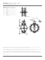
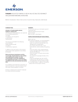
Parts list
1. Body
2. Disc
3. Seat
4. Shaft
5. Disc screw
6. O-ring
7. Bushing
8. Plug
9. O-ring
10. Circlip
11. Dirt scraper
Mounting holes
Key-way sizes 350 - 600mm
Parallel flats sizes
150 - 300mm
Sizes
150 - 300mm
only
PCD
KEYSTONE BUTTERFLY VALVES FIGURE 55
INSTALLATION AND MAINTENANCE INSTRUCTIONS
Neither Emerson, Emerson Automation Solutions, nor any of their affiliated entities assumes responsibility for the selection, use or maintenance of any product.
Responsibility for proper selection, use, and maintenance of any product remains solely with the purchaser and end user.
Keystone is a mark owned by one of the companies in the Emerson Automation Solutions business unit of Emerson Electric Co. Emerson Automation Solutions, Emerson
and the Emerson logo are trademarks and service marks of Emerson Electric Co. All other marks are the property of their respective owners.
The contents of this publication are presented for informational purposes only, and while every effort has been made to ensure their accuracy, they are not to be
construed as warranties or guarantees, express or implied, regarding the products or services described herein or their use or applicability. All sales are governed by
our terms and conditions, which are available upon request. We reserve the right to modify or improve the designs or specifications of such products at any time without
notice.
Emerson.com/FinalControl
-
 1
1
-
 2
2
-
 3
3
-
 4
4
-
 5
5
-
 6
6


Keystone Butterfly valves Figure 55 Owner's manual
- Type
- Owner's manual
Ask a question and I''ll find the answer in the document
Finding information in a document is now easier with AI
Related papers
-
Keystone Series 320 Butterfly valves Owner's manual
-
Keystone Butterfly valves ParaSeal Owner's manual
-
-
-
-
-
-
-
-
Other documents
-
 Neotecha Inline Sampling O&SI User guide
-
Watts BF03-121-1P-M2 4 Installation guide
-
 Neotecha Neoseal Butterfly Valve Owner's manual
-
 Neotecha Ball check valve type KR / Sightglass type SG User guide
-
Bettis BHH Series Hydraulic Double-Acting Balanced Rotary Actuator 90° Quarter-Turn Owner's manual
-
 Fasani Assisted swing check valve bolted bonnet Owner's manual
-
Vanessa Series 30,000 Triple Offset Valve – IOM Owner's manual
-
Emerson Vanessa 30000 Series Installation And Maintenance Instructions Manual
-
 Fasani Bolted Bonnet Globe Valves Owner's manual
-
 Fasani Gate Valves Owner's manual


