
www.samlex.com
www.samlex-solar.com
BSB-250 DUAL
Model No.
BATTERY SEPARATOR
OWNER’S MANUAL / BEDIENUNGSANLEITUNG
GEBRUIKSAANWIJZING
Please read this manual before operating your seperator
Intelligent Battery Seperator

• Auto 12V/24V detection • Latching relay
• Handling of high currents • Very low stand-by current
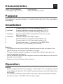
Characteristics
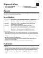
Purpose
The charging of an extra battery in a vehicle without the risk of the main battery
discharging.
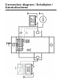
1. Connect the plus (+) of the secondary battery to T2.
2. (optional). Connect the battery charger plus terminal (+) to T2.
3. Connect the plus (+) of the secondary battery to A2.
4. (optional). Connect a push switch that switches to plus (+) to the
Start connection.
5. (optional). Connect a lamp to the status output.
6. Connect the plus (+) of the primary battery to T1.
7. Connect the plus (+) of the primary battery to A1.
8. Connect the minus (–) connection of the BSB-250 to
the minus (–) of the battery via a 5A fuse.
Warning:
• The product should only be fitted by qualified personal who are aware of the
requirements for working with high battery voltages.
• The use of faulty connection material or wires with insufficient diameter can
result in damaged equipment.
• A short between the positive and negative terminal of the battery can do serious
damage to your system.
• Alsways use fuses between all connections
Installation
General
• All the voltages referred to here apply to a 12V system. For a complete overview
of all voltages for both the 12V and 24V systems, please consult the table below
on the right.
• The LED is an indication of the status of the relay. If this is illuminated or flashes,
the relay is closed. If the LED is off, the relay is open.
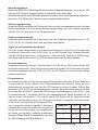
Operation
UK

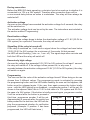
During connection
Before the BSB-250 starts operating, a decision has to be made as to whether it is
connected to a 12V or a 24V system. Therefore after connection there will be
a one second delay before an action is undertaken. The relay will then always be
switched off.
Activation voltage
As soon as the voltage has exceeded the activation voltage for 5 seconds, the relay
will be switched on.
The activation voltage level can be set by the user. The instructions are included in
the section entitled ‘Programming’.
Deactivation voltage
As soon as the voltage drops to below the deactivation voltage of 11.8V (23.6V for
24V system) for a period of 5 seconds, the relay will switch off.
Signalling (if the relay is turned off)
If the relay is switched on, it will issue a signal when the voltage has been below
12.8V (25.6V for 24V system) for a minimum of 5 seconds. At that moment
the LED will start flashing (1 sec. on, 1 sec. off). The signal stops after a minute and
both the LED and the relay will switch off.
Excessively high voltage
As soon the voltage has exceeded 16V (32V for 24V system) for at least 1 second,
the relay will switch off. If the voltage is then present for, in any case, 5
seconds between the activation voltage and 15.6V (31.6V for 24V system), the relay
will switch on again.
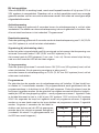
Programming
The user can set the value of the activation voltage himself. When doing so he can
choose from 3 different values. The programming mode is activated by pressing
the programming button until the LED starts flashing. As soon as this happens, the
button must be released again. If the user then again presses the button briefly
once – with the LED lighting up as feedback – programme number 1 will be set. As
shown in the adjacent table, this is 13.2V in the case of a 12V system and 26.4V in
the case of a 24V system. If the button is briefly pressed again, programme number
2 will be set and after the button is pressed a
third time, programme number 3 will be set.
Approximately 4 seconds after the switch has
been pushed for the last time, the LED will dis-
play the programmed situation for verification
purposes. (example: If position 2 has been
programmed, the LED will flash twice.)
prog no. 12V 24V
*1 13.2 V 26.4 V
2 13.5 V 27.0 V
3 13.8 V 27.6 V
*) factory setting

Start assistance
As soon as the Start input is connected to the plus (+) of the primary battery, the
relay will switch on immediately. From the moment this connection is broken,
the relay will continue to operate for 30 seconds.
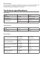
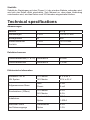
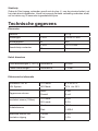
Weight 370 g
Dimensions WxHxD 82x57x120 mm
Mounting holes Ø 19x2x18 mm
Terminal strips
WxHxD 27.6 V
Ø 8 mm
Weight 12V 24V
Dimensions 13.2 V 26.4 V
Flange connectors (T1 & T2)
12V mode 8 V to 20 V
24V mode 20 V to 35 V
Current consumption
Active 3 mA
Passive 2 mA
Input surge current (100ms)
12V mode 2.6 A
24V mode 5.0 A
Switch current
Continues 250 A
Peak 1,500 A
Maximum flow from Continues 0.5 A
the status exit Peak 1.0 A
Dimensions
Cable diameters
Electrical data
Technical specifications
Page is loading ...
Page is loading ...
Page is loading ...
Page is loading ...
Page is loading ...
Page is loading ...

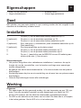
Connection diagram / Schaltplan /
Aansluitschema
Programmeren
De gebruiker kan de waarde van de activatiespanning zelf instellen. Hij kan hierbij keuze maken uit 3 verschillende waarden. De
programeerstand wordt geactiveerd door de programmeerknop in te drukken tot de LED gaat knipperen. Zodra dit gebeurd moet
de knop weer losgelaten worden. Als de gebruiker vervolgens eenmaal de knop kort indrukt – waarbij de LED als terugkoppeling
oplicht – wordt programma nummer 1 ingesteld. Zoals in de tabel hiernaast te zien is, is dit bij een 12V systeem 13,2V en bij
een 24V systeem 26,4V. Als nogmaals de knop kort ingedrukt wordt zal programma nummer 2 ingesteld worden en na een
derde maal op de knop drukken zal programma nummer 3 ingesteld worden. Ongeveer 4 seconden na het laatst indrukken van
de knop zal de LED de geprogrammeerde stand ter controle nogmaals weergeven. (voorbeeld: Als stand 2 is geprogrammeerd, zal de LED twee maal
knipperen.)
Starthulp
Zodra de Start ingang verbonden wordt met de plus (+) van de primaire batterij, zal het relais direct inschakelen. Vanaf het moment dat deze verbinding
verbroken wordt, zal het relais nog 30 seconden ingeschakeld blijven.
Technische gegevens
Dimensies
Gewicht 370 g
Afmetingen L*B*H 120*82*57 mm
Montagegaten Ø 5 mm
Aansluitstrip contacten
L*B*H
Ø
18*19*2 mm
8 mm
Kabel diameters
Flens aansluitingen (T1 & T2) minimale Ø 50 mm
2
Faston aansluitingen minimale Ø 1,5 mm
2
Elektronische informatie
Autodetect 12V of 24V systeem
12V mode
24V mode
8 V t/m 20 V
20 V t/m 35 V
Opgenomen stroom
Actief
Passief
3 mA
2 mA
Inschakel stroom (100ms)
12V mode
24V mode
2,6 A
5,0 A
Schakelstroom
Continu
Piek
250 A
1.500 A
Maximale stroom van de status uitgang
Continu
Piek
0,5 A
1,0 A
Connection diagram / Schaltplan / Aansluitschema
prog nr. 12V 24V
1 13,2V 26,4V
2 13,5V 27,0V
3 13,8V 27,6V
Page is loading ...
-
 1
1
-
 2
2
-
 3
3
-
 4
4
-
 5
5
-
 6
6
-
 7
7
-
 8
8
-
 9
9
-
 10
10
-
 11
11
-
 12
12


Ask a question and I''ll find the answer in the document
Finding information in a document is now easier with AI
in other languages
- Deutsch: Samlexpower BSB 250 DUAL Bedienungsanleitung
- Nederlands: Samlexpower BSB 250 DUAL de handleiding
Related papers
-
Samlexpower BSM 140 DUAL Owner's manual
-
-
-
Samlexpower BS 500 DUAL Owner's manual
-
Samlexpower BS 100 DUAL Owner's manual
-
-
Samlexpower BGB 250 Owner's manual
-
Samlexpower BG 200 Owner's manual
-
Other documents
-
Victron energy BatteryProtect 65A/100A/220A Owner's manual
-
-
-
-
-
-
-
-
-