

Datalogic S.r.l.
Via S. Vitalino 13
40012 Calderara di Reno
Bologna - Italy
© 2014 - 2017 Datalogic S.p.A. and/or its affiliates ALL RIGHTS RESERVED. Without limiting the rights
under copyright, no part of this documentation may be reproduced, stored in or introduced into a retrieval
system, or transmitted in any form or by any means, or for any purpose, without the express written
permission of Datalogic S.p.A. and/or its affiliates.
Datalogic and the Datalogic logo are registered trademarks of Datalogic S.p.A. in many countries, including
the U.S.A. and the E.U.
All other trademarks and brands are property of their respective owners. Datalogic reserves the right to
make modifications and improvements without prior notification.
16/06/17

INDEX
1. Safety summary ................................................................................................................. 1
2. Identification ...................................................................................................................... 3
3. Mechanical installation ...................................................................................................... 4
3.1 Solid shaft encoders ...................................................................................................... 4
3.1.1 Customary installation ............................................................................................ 4
3.1.2 Installation using fixing clamps (code LKM-386) ..................................................... 4
3.1.3 Installation using a flange (code ST-58-FLNG) ....................................................... 5
3.2 Hollow shaft encoders .................................................................................................... 6
3.2.1 AMT58-H15 ............................................................................................................ 6
4. Electrical connections ....................................................................................................... 7
4.1 PWR Power supply connector (Fig.1) ........................................................................... 7
4.2 P1 Port 1 and P2 Port 2 connectors (Fig.1)................................................................... 8
4.3 Ground connection (Fig.1) ............................................................................................. 8
4.4 MAC address and IP address ....................................................................................... 8
4.5 Diagnostic LEDs (Fig.1) ................................................................................................ 9
5. Getting started 10
5.1 Configuring the encoder with Siemens SIMATIC STEP 7 ........................................... 10
5.2 Mac address ................................................................................................................ 10
5.3 Encoder installation under STEP 7 environment ......................................................... 11
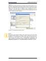
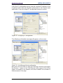
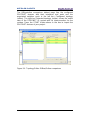
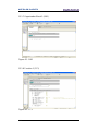
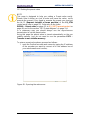
5.3.1 Description of the GSDML file .............................................................................. 11
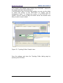
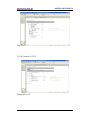
5.3.2 Installing the GSDML file ...................................................................................... 12
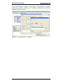
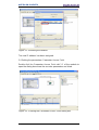
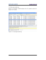
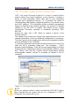
5.3.3 Inserting the module in the Profinet-IO system ..................................................... 15
5.3.4 Device name and IP address at delivery .............................................................. 17
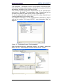
5.3.5 Setting the device name ....................................................................................... 17
5.3.6 Checking the device name ................................................................................... 26
5.3.7 Setting the IP address .......................................................................................... 27
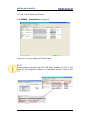
5.4 Setting the parameters: Parameter Access Point ........................................................ 30
5.5 Resetting the parameters to default factory values ..................................................... 32
6. Profinet interface ............................................................................................................. 37
6.1 A brief introduction to Profinet ..................................................................................... 37
6.2 Profinet encoders from Datalogic Automation s.r.l. ..................................................... 38
6.2.1 Overview of the encoder profiles .......................................................................... 39
6.3 Application Class definition ......................................................................................... 39
6.3.1 Application Class 3 ............................................................................................... 39
6.3.2 Application Class 4 ............................................................................................... 39
6.4 Encoder Object model ................................................................................................. 39
6.5 Encoder object architecture ......................................................................................... 40
7. PROFINET IO data description ....................................................................................... 42
7.1 Telegrams ................................................................................................................... 42
7.1.1 Standard Telegram 81 .......................................................................................... 42
7.1.2 Standard Telegram 82 .......................................................................................... 42
7.1.3 Standard Telegram 83 .......................................................................................... 43
7.1.4 Standard Telegram 84 .......................................................................................... 43

8. Cyclic Data Exchange–Standard signals ....................................................................... 44
G1_XIST1 ......................................................................................................................... 45
G1_XIST2 ......................................................................................................................... 46
G1_XIST3 ......................................................................................................................... 47
STW2_ENC ....................................................................................................................... 47
Control by PLC .................................................................................................................. 47
ZSW2_ENC ....................................................................................................................... 48
Control requested .............................................................................................................. 48
G1_STW ........................................................................................................................... 49
Home position mode ......................................................................................................... 49
Request set/shift of home position .................................................................................... 49
Request absolute value cyclically ...................................................................................... 51
Activate parking sensor ..................................................................................................... 51
Acknowledging a sensor error ........................................................................................... 52
G1_ZSW ........................................................................................................................... 52
NIST_A ............................................................................................................................. 52
NIST_B ............................................................................................................................. 52
9. Acyclic Data Exchange .................................................................................................... 53
9.1 Index 0xAFF0: Identification & Maintenance (I&M) functions ...................................... 53
9.2 Index 0xB02E : supported PROFIdrive specific parameters ....................................... 54
P922 – Telegram Selection ........................................................................................... 54
P964 – Profidrive Parameter : Device identification ....................................................... 54
P965 – Encoder profile number ..................................................................................... 54
P971 – Transfer to non volatile memory ........................................................................ 54
P975 – Encoder object identification ............................................................................. 55
P979 – Sensor format .................................................................................................... 56
P980 – Number list of defined parameter ...................................................................... 56
P61001 – IP of station ................................................................................................... 56
9.3 Index 0xB02E : supported encoder specific parameters ............................................. 57
P65000 – Preset value ................................................................................................... 57
P65001 – Operating status ............................................................................................ 57
9.4 Index 0xBF00 : user parameter data ........................................................................... 59
Code sequence ............................................................................................................. 59
Class 4 functionality ....................................................................................................... 60
G1_XIST1 preset control ............................................................................................... 60
Scaling function control ................................................................................................. 61
Alarm channel control .................................................................................................... 61
Compatibility mode ........................................................................................................ 62
Scaling function parameters .......................................................................................... 62
Measuring units / Revolution ......................................................................................... 63
Total measuring range ................................................................................................... 63
Maximum Master Sign-Of-Life failures .......................................................................... 64
Velocity measuring units ................................................................................................ 65
9.5 "Red Zone" .................................................................................................................. 66
10. Diagnostics and Alarms .................................................................................................. 68
10.1 Acyclic diagnosis parameter ...................................................................................... 69
10.2 Error messages via the Alarm Channel ..................................................................... 69
10.2.1 Use of the ChannelErrorType ............................................................................. 70
10.3 Error codes in ............................................................................................................ 70
10.4 LED indication ........................................................................................................... 70

11. Real time class communication ..................................................................................... 71
11.1 Real-time classes in PROFINET IO .......................................................................... 71
11.2 Real-Time class 2 (RT2) – Not synchronized ............................................................ 71
11.3 Real-Time class 3 (IRT_TOP) (RT3) ......................................................................... 73
11.3.1 Setting an isochronous communication .............................................................. 74
11.4 OB61 ......................................................................................................................... 85
11.5 PIP (Process Image Partition) ................................................................................... 86
11.5.1 Consistency ........................................................................................................ 86
11.5.2 SFC126 “SYNC_PI” ............................................................................................ 87
11.5.3 SFC127 “SYNC_PO” .......................................................................................... 87
11.6 Domain Management ............................................................................................ 88
11.7 Topology Editor ..................................................................................................... 92
11.8 Message monitoring .............................................................................................. 96
12. Encoder replacement using LLDP ................................................................................. 97
13. Read & write records in acyclic communication .......................................................... 98
13.1 Example: reading and writing a parameter (Preset Value) ........................................ 99
13.1.1 System Function Block 52 (SFB52) .................................................................... 99
13.1.2 System Function Block 53 (SFB53) .................................................................... 99
13.1.3 Data Block 1 (DB1) ........................................................................................... 100
13.1.4 Data Block 2 (DB2) ........................................................................................... 100
13.1.5 Data Block 3 (DB3) ........................................................................................... 101
13.1.6 Data Block 4 (DB4) ........................................................................................... 101
13.1.7 Organization Block 1 (OB1) .............................................................................. 102
13.1.8 Function 1 (FC1) ............................................................................................... 102
13.1.9 Function 2 (FC2) ............................................................................................... 103
13.1.10 Acyclic request of Preset ................................................................................ 104
13.2 Monitoring a variable ............................................................................................... 105
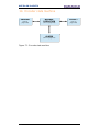
14. Encoder state machine .................................................................................................. 106
14.1 Normal operation diagram ....................................................................................... 107
14.2 Preset diagram ........................................................................................................ 108
14.3 Parking sensor diagram .......................................................................................... 109
14.4 Error diagram .......................................................................................................... 110
14.4.1 Acknowledgment of acknowledgeable sensor error ......................................... 110
14.4.2 Acknowledgment of not acknowledgeable sensor error .................................... 111
15. Integrated web server .................................................................................................... 112
15.1 Firmware upgrade ................................................................................................... 119
15.2 Setting the preset value........................................................................................... 125
16. Default parameters list .................................................................................................. 128

Subject Index
A
Acknowledging a sensor error ............... 52
Activate parking sensor.......................... 51
Alarm channel control ............................ 61
C
Class 4 functionality ............................... 60
Code sequence ...................................... 59
Compatibility mode ................................ 62
Control by PLC ...................................... 47
Control requested .................................. 48
Controller Sign-Of-Life ........................ 47
E
Encoder Sign-Of-Life ........................... 48
G
G1_STW ................................................ 49
G1_XIST1 .............................................. 45
G1_XIST1 preset control ....................... 60
G1_XIST2 .............................................. 46
G1_XIST3 .............................................. 47
G1_ZSW ................................................ 52
H
Home position mode .............................. 49
I
Index 0xAFF0 ........................................ 54
Index 0xB02E
supported encoder specific parameters
....................................................... 57
supported PROFIdrive specific
parameters ..................................... 54
Index 0xBF00 ......................................... 59
M
Maximum Master Sign-Of-Life failures ... 64
Measuring units / Revolution .................. 63
N
NIST_A .................................................. 52
NIST_B .................................................. 52
P
P61001 – IP of station ............................ 56
P65000 – Preset value ........................... 57
P65001 – Operating status .................... 57
P922 – Telegram Selection .................... 54
P964 – Profidrive Parameter
Device identification ........................... 54
P965 – Encoder profile number ............. 54
P971 – Transfer to non volatile memory 54
P975 – Encoder object identification ...... 55
P979 – Sensor format ............................ 56
P980 – Number list of defined parameter
........................................................... 56
R
Request absolute value cyclically .......... 51
Request set/shift of home position ......... 49
S
Scaling function control .......................... 61
Standard Telegram 81 ........................... 42
Standard Telegram 82 ........................... 42
Standard Telegram 83 ........................... 43
Standard Telegram 84 ........................... 43
STW2_ENC ........................................... 47
T
Total measuring range ........................... 63
V
Velocity measuring units ........................ 65
Z
ZSW2_ENC ........................................... 48

Table of figures
Figure 1 - Connectors and diagnostic LEDs ........................................................................ 7
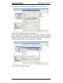
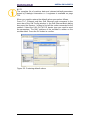
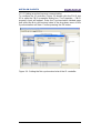
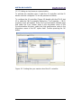
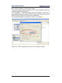
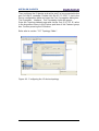
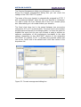
Figure 2 - Installing the GSDML file ................................................................................... 12
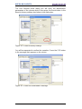
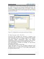
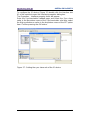
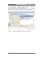
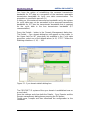
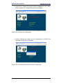
Figure 3 - Selecting the GSDML file .................................................................................. 13
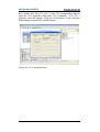
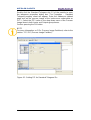
Figure 4 - GSDML file installation ...................................................................................... 13
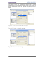
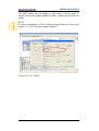
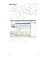
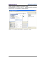
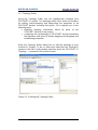
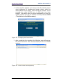
Figure 5 - Scrolling through Profinet families and categories ............................................. 14
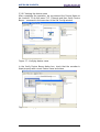
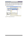
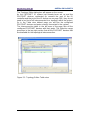
Figure 6 - Inserting a module in the Profinet-IO system ..................................................... 15
Figure 7 - Inserted module ................................................................................................. 15
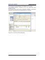
Figure 8 - Adding the Standard Telegram .......................................................................... 16
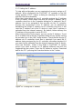
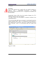
Figure 9 - Assigning the device name ................................................................................ 19
Figure 10 - Assigning the IP address ................................................................................. 20
Figure 11 - Downloading data to the PLC .......................................................................... 21
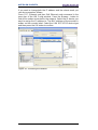
Figure 12 - Assigning the device name .............................................................................. 22
Figure 13 - Confirming the device name ............................................................................ 23
Figure 14 - Edit Ethernet Node dialog box ......................................................................... 24
Figure 15 - Edit Ethernet Node confirmation ...................................................................... 25
Figure 16 - Browsing the network ...................................................................................... 25
Figure 17 - Verifying device name ..................................................................................... 26
Figure 18 - Verifying device name ..................................................................................... 26
Figure 19 - Setting the IP address ..................................................................................... 27
Figure 20 - Browsing the network ...................................................................................... 28
Figure 21 - Assigning IP configuration ............................................................................... 29
Figure 22 - Edit Ethernet Node confirmation ...................................................................... 29
Figure 23 - Browsing the network ...................................................................................... 30
Figure 24 - Entering the Parameter Access Point dialog box ............................................. 30
Figure 25 - Parameter Access Point properties ................................................................. 31
Figure 26 - Downloading data to the PLC .......................................................................... 31
Figure 27 - Parameter Access Point help messages ......................................................... 32
Figure 28 - Restoring default values .................................................................................. 33
Figure 29 - Reset to factory settings .................................................................................. 34
Figure 30 - Reset first confirmation message .................................................................... 34
Figure 31 - Reset second confirmation message ............................................................... 35
Figure 32 - Reset executed message ................................................................................ 35
Figure 33 - Checking data after reset ................................................................................ 36
Figure 34 - Setting the Not synchronized role of the IO controller ..................................... 72
Figure 35 - Setting the Not synchronized role of the IO device .......................................... 73
Figure 36 - Setting the sync master role of the IO controller .............................................. 74
Figure 37 - Setting the sync slave role of the IO device ..................................................... 75
Figure 38 - CPU property sheet ......................................................................................... 76
Figure 39 - PIP of OB61 ..................................................................................................... 77
Figure 40 - OB61: assigning IO device in isochronous mode ............................................ 78
Figure 41 - Standard Telegram as isochronous submodule .............................................. 79
Figure 42 - Setting PIP for Standard Telegram IOs ........................................................... 80
Figure 43- Configuring the IO controller topology .............................................................. 81
Figure 44 - Configuring the IO device topology .................................................................. 82
Figure 45 - Checking the Profinet IO isochronous mode ................................................... 83
Figure 46 - Isochronous Mode dialog box .......................................................................... 84

Figure 47 - OB61 ............................................................................................................... 85
Figure 48 - Process Image Partition .................................................................................. 86
Figure 49 - Assigning the IO device to a sync domain ....................................................... 89
Figure 50 - Domain management dialog box ..................................................................... 90
Figure 51 - Sync domain details dialog box ....................................................................... 91
Figure 52 - Entering the Topology Editor ........................................................................... 92
Figure 53 - Topology Editor: Table view ............................................................................ 93
Figure 54 - Topology Editor: Offline/Online comparison .................................................... 94
Figure 55 - Topology Editor: Graphic view ......................................................................... 95
Figure 56 - Message monitoring ........................................................................................ 96
Figure 57 - Link Layer Discovery Protocol (LLDP) ............................................................. 97
Figure 58 - Base mode parameter request and response ................................................. 98
Figure 59 - SFB52 ............................................................................................................. 99
Figure 60 - SFB53 ............................................................................................................. 99
Figure 61 - DB1 ............................................................................................................... 100
Figure 62 - DB2 ............................................................................................................... 100
Figure 63 - DB3 ............................................................................................................... 101
Figure 64 - DB4 ............................................................................................................... 101
Figure 65 - OB1 ............................................................................................................... 102
Figure 66 - FC1 ................................................................................................................ 102
Figure 67 - FC1 ................................................................................................................ 103
Figure 68 - FC2 ................................................................................................................ 103
Figure 69 - Acyclic request of Preset value ...................................................................... 104
Figure 70 - Monitoring a variable ..................................................................................... 105
Figure 71 - Encoder state machine .................................................................................. 106
Figure 72 - Opening the web server ................................................................................ 112
Figure 73 - Web server Index page ................................................................................. 113
Figure 74 - Encoder Information page ............................................................................. 113
Figure 75 - Firmware upgrade page ................................................................................ 114
Figure 76 - Status & Alarms page .................................................................................... 114
Figure 77 - Encoder Parameters page ............................................................................. 115
Figure 78 - Encoder Specific Profile Parameters page .................................................... 115
Figure 79 - Encoder Specific Profile Parameters page 1 ................................................. 116
Figure 80 - Encoder Specific Profile Parameters page 2 ................................................. 116
Figure 81 - Identification & Maintenance page ................................................................. 117
Figure 82 - Change the preset value page ....................................................................... 118
Figure 83 - Reserved area page ...................................................................................... 118
Figure 84 - Opening the web server ................................................................................ 120
Figure 85 - Web server Index page ................................................................................. 120
Figure 86 - Confirming the access to the Firmware upgrade page .................................. 121
Figure 87 - Firmware upgrade page ................................................................................ 121
Figure 88 - Web server stopped ...................................................................................... 122
Figure 89 - Firmware upgrade executable file .................................................................. 122
Figure 90 - Starting the firmware upgrade operation ....................................................... 123
Figure 91 - Firmware upgrade operation process ............................................................ 124
Figure 92 - Opening the web server ................................................................................ 125
Figure 93 - Web server Index page ................................................................................. 126
Figure 94 - Confirming the access to the Preset page ..................................................... 126
Figure 95 - Changing the Preset value ............................................................................ 127
Figure 96 - Preset value stored properly .......................................................................... 127

Typographic and iconographic conventions
In this guide, to make it easier to understand and read the text the following typographic
and iconographic conventions are used:
parameters and objects of both Datalogic Automation s.r.l. device and interface are
coloured in ORANGE;
alarms are coloured in RED;
states are coloured in FUCSIA.
When scrolling through the text some icons can be found on the side of the page: they are
expressly designed to highlight the parts of the text which are of great interest and
significance for the user. Sometimes they are used to warn against dangers or potential
sources of danger arising from the use of the device. You are advised to follow strictly the
instructions given in this guide in order to guarantee the safety of the user and ensure the
performance of the device. In this guide the following symbols are used:
This icon, followed by the word WARNING, is meant to highlight the
parts of the text where information of great significance for the user can
be found: user must pay the greatest attention to them! Instructions
must be followed strictly in order to guarantee the safety of the user and
a correct use of the device. Failure to heed a warning or comply with
instructions could lead to personal injury and/or damage to the unit or
other equipment.
This icon, followed by the word NOTE, is meant to highlight the parts of
the text where important notes needful for a correct and reliable use of
the device can be found. User must pay attention to them! Failure to
comply with instructions could cause the equipment to be set wrongly:
hence a faulty and improper working of the device could be the
consequence.
This icon is meant to highlight the parts of the text where suggestions
useful for making it easier to set the device and optimize performance
and reliability can be found. Sometimes this symbol is followed by the
word EXAMPLE when instructions for setting parameters are
accompanied by examples to clarify the explanation.

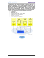
Preliminary information
This guide is designed to provide the most complete information the operator needs to
correctly and safely install and operate the following encoders fitted with Profinet interface:
AMT58…PN (DAP 1 : multiturn encoder 13 +14 bits)
To make it easier to read the text, this guide can be divided into some main sections.
In the first section (from chapter 1 to chapter 4) general information concerning the safety,
the mechanical installation and the electrical connection.
In the second section (chapter 5) information on how to install and configure the encoder
in the STEP 7 development environment as well as tips for setting up and running properly
and efficiently the unit are provided.
In the third section (from chapter 6 to chapter 12) both general and specific information is
given on the Profinet interface.
In this section the interface features and the parameters implemented in the unit are fully
described.
In the last section (from chapter 13 to chapter 15) some examples of programming and
advanced maintenance information are explained.

Glossary of Profinet terms
PROFINET IO, like many other networking systems, has a set of unique terminology.
Table below contains a few of the technical terms used in this guide to describe the
PROFINET IO interface. Sometimes they also refer more specifically to the S7
programming environment. They are listed in alphabetical order.
Acyclic
Communications
Unscheduled, on demand communications. Diagnostic messages from
an IO Supervisor to an IO Device are Acyclic. Refer to page 58.
AP Application Process - The application process running in the device.
PROFINET supports a default Application Processes and additional
profile specific application processes.
API The value of the API (Application Process Identifier) parameter
specifies the application that is processing the IO data. PROFINET
standard IEC 61158 assigns profiles to certain APIs (PROFIdrive,
PROFIslave) which are defined by the PROFINET User Organization.
The standard API is 0.
Application class
A
n application class specifies a number of mandatory functions and
addition optional functions to be supported by an IO device. The
Profinet encoders can be configured as CLASS 3 and CLASS 4
PROFINET IO devices according to the encoder profile. Refer to page
41
AR Application Relation - The relationship between a PROFINET IO
Controller and an IO device. A PROFINET IO device can support more
than one Application Relationship.
Bus
A
bus is a communication medium connecting several nodes. Data
can be transferred via serial or parallel circuits, that is, via electrical
conductors or fiber optic.
Channel A single IO point. A Channel can be discrete or analog.
Consumer Status The Status an IO device provides to an IO Controller for the data it
consumes from IO Controller.
CR Communication Relationship -
A
virtual communication channel within
an AR.
Cyclic
Communications
Scheduled, repetitive communications. IO data and alarm transfers are
cyclic.
Data block In contrast to code blocks, data blocks (DB) do not contain Step 7
statements. They are used to save data, i.e. variable data which are
processed by the user program. Global data blocks serve to
accommodate user data which can be used by all other blocks.
DCP Discovery Control Protocol -
A
communications protocol with
PROFINET IO that allows an IO Controller or Supervisor to find every
PROFINET IO device on a subnet.

Determinism Determinism means that a system responds in a predictable
(deterministic) manner.
Device name Before an IO device can be addressed by an IO controller, it must have a
device name. In PROFINET, this method was selected because it is
simpler to work with names than with complex IP addresses.
Refer to page 18
Encoder
Profile
The PROFINET profile for Encoders is intended to define a standard
application interface for encoders. The profile is a supplement to the
PROFIdrive profile, so it is mandatory to read the PROFIdrive profile
before implementing the encoder profile. Profinet encoders from Datalogic
Automation s.r.l.comply with the Encoder Profile Specifications V4.1
version 3.162. See also “Profile“.
Function Functions (FC) are code blocks which can be programmed by the user. A
FC does not have a “memory”. Temporary variables as well as
parameters transferred to the function when the latter is called are saved
in a L stack. They are lost following processing of the FC.
Function block Function blocks (FB) are code blocks with a “memory” which are
programmed by the user. They have an assigned instance data block
(instance DB) as memory. Parameters transferred to a FB as well as the
static variables are saved in this data block. An FB contains a program
which is always executed when the FB is called by another code block.
Function blocks facilitate the programming of frequently repeated,
complex functions.
Frame ID The two-byte field in the Ethernet frame which defines the type of
PROFINET IO message.
GSD The properties of a PROFINET device are described in a GSD file
(General Station Description) that contains all the information required for
configuration. In PROFINET IO, the GSD file is in XML format. The
structure of the GSD file conforms to ISO 15734, which is the world-wide
standard for device descriptions. Refer to page 11
GSDML General Station Description Markup Language – The file containing the
XML description of the PROFINET IO device. Refer to page 11
IO Controller Device used to address the connected IO devices. This means that the IO
controller exchanges input and output signals with assigned field devices.
The IO controller is often the controller on which the automation program
runs. Refer to page 39
IO Device A decentralized field device that is assigned to one of the IO controllers
(e.g. remote IO, encoders, valve terminals, frequency converters,
switches, etc.). Refer to page 39
IO Parameter
Server
An IO Parameter Server is a server station, usually a PC, for loading and
saving the configuration data (records) of IO Devices.
IO Supervisor Programming device, PC or HMI device used for commissioning and
diagnostics of IO Controllers and IO Devices. Refer to page 39.
IP address The IP address is the name of the unit in a network using the Internet
protocol. Refer to page 8.

IRT Synchronized transmission procedure for the cyclic exchange of IRT data
between PROFINET devices. A reserved bandwidth within the send clock
is available for the IRT IO data. The reserved bandwidth ensures that the
IRT data can be transmitted at reserved, synchronized intervals whilst
remaining uninfluenced even by other greater network loads (e.g. TCP/IP
communication or additional real time communication). The "high
flexibility" enables simple planning and expansion of the system. A
topological configuration is not required. Refer to page 77.
MAC address The MAC address is an identifier unique wordlwide consisting of two
parts: the first 3 bytes are the manufacturer ID and are provided by IEE
standard autority; the last three bytes represent a consecutive number of
the manufacturer. Refer to page 8.
Module Modules are user defined components that plug into slots. Modules can
be real or virtual.
NRT Non Real Time - The non Real Time PROFINET IO Channel.
Configuration and diagnostic messages are transferred over the NRT
Channel.
Organization
block
A
range of organization blocks (OB) are designed to execute the user
program. OBs are the interface interface between the user program and
the operating system of a CPU. They permit event-controlled processing
of special program components within the user program.The order in
which the user program is executed is defined in the organization blocks.
Profile Profiles define application-specific functionality to ensure the openness of
PROFIBUS and PROFINET is utilized consistently. PI Profiles can cover
simple devices such as encoders by defining how signals are used and
how they are physically connected. However, profiles are increasingly
covered more complex systems or requirements. Profiles such as
PROFIdrive and PROFIsafe deliver active functionality as well. An
advanced profile covering active power management for end devices like
lasers and robots is now under development with the aim of bringing
significant reductions in energy consumption for the automotive industry.
Profiles guarantee quicker system design and they support faster device
interchange, promoting competition amongst vendors, increased choice
for users and full interoperability.
Provider
Status
The Status an IO device provides to an IO Controller with the data
transferred to the Controller.
Proxy A device which maps non PROFINET IO data to PROFInet.
Real-time Real-time means that a system processes external events within a
defined time. If the reaction of a system is predictable, one speaks of a
deterministic system. The general requirements for real-time are
therefore: deterministic response and defined response time. Refer to
page 77.
RT Real Time - The Real Time PROFINET IO Channel. I/O and Alarm Data
are transferred over the RT Channel. Refer to page 77.
Slot A group of one or more Subslots. Slots can be real or virtual.
Standard
signal
The encoder profile defines a series of standard signals which are used to
configure the IO data. Refer to page 46.

Submodule
A
component of a module that is plugged into a subslot. A submodule is
real or virtual.
Subslot A group of one or more channels. Subslots can be real or virtual.
Sync domain
A
ll PROFINET devices that are to be synchronized via PROFINET IO with
IRT must belong to a sync domain. The sync domain consists of precisely
one sync master and at least one sync slave. IO controllers and switches
can hold the role of a sync master or sync slave. Other IO devices
support only the role as sync slave. Refer to page 94.
System
function
System functions (SFC) are integral functions in the operating system of a
S7 CPU. In addition, SFCs are frequently called implicitly by SFBs. SFCs
can be called by the user program like normal functions. SFCs are used
to implement a number of important system functions for Profinet IO.
System
function block
System function blocks (SFB) are integral functions in the operating
system of a S7 CPU. SFBs can be called by the user program like normal
function blocks. SFBs are used to implement a number of important
system functions for Profinet IO.
TCP/IP The Ethernet system is designed solely to carry data. It is comparable to
a highway as a system for transporting goods and passengers. The data
is actually transported by protocols.
This is comparable to cars and commercial vehicles transporting
passengers and goods on the highway.
Tasks handled by the basic Transmission Control Protocol (TCP) and
Internet Protocol (IP) (abbreviated to TCP/IP):
1. The sender splits the data into a sequence of packets.
2. The packets are transported over the Ethernet to the correct recipient.
3. The recipient reassembles the data packets in the correct order.
4. Faulty packets are sent again until the recipient acknowledges that
they have been transferred successfully.
Telegram
A
telegram is a rigidly defined bit stream carrying data. A telegram
specifies the data length and the type of data which is sent to and from
the IO controller. The encoder profile supports Standard Telegrams 81,
82, 83 and 84. Refer to page 44.
Topology Network structure. Commonly used structures:
Line topology;
Ring topology;
Star topology;
Tree topology.
Refer to page 94.
Transmission
rate
Data transfer rate (in bps).
User program The user program contains all instructions, declarations and data for
signal processing required to control a plant or a process. It is assigned to
a programmable module (for example CPU) and can be structured in
smaller units (blocks).

List of abbreviations
Table below contains a list of abbreviations (in alphabetical order) which may be used in
this guide to describe the PROFINET IO interface. Sometimes they also refer more
specifically to the S7 programming environment.
AR Application Relation
API Application Process Identifier
C-LS Controller’s Sign-Of-Life
CR Communication Relation
DB Data block
DO Drive Object
DO-LS Driver Object Sign-Of-Life
DU Drive Unit
EO Encoder Object
EU Encoder Unit
FB Function block
FC Function
I&M Identification & Maintenance
IRT Isochronous Real Time Ethernet
IRT Flex IRT “High Flexibility”
IRT Top IRT “High Performance”
GSDML General Station Description Markup Language
IO Input/Output
IP Internet Protocol
LLDP Link Layer Discovery Protocol
LS Sign-Of-Life
MAC Media Access Control
MAP Module Access Point
MLS Master Sign-Of-Life
OB Organization block
PAP Parameter Access Point
PI PROFIBUS and PROFINET International
RT Real Time Ethernet
SFB System function block
SFC System function
TCP Transmission Control Protocol
T
MAPC
Master Application Cycle Time


AMT58x-PN ProfiNET®
1
1. Safety summary
Safety
Always adhere to the professional safety and accident prevention
regulations applicable to your country during device installation and
operation;
installation and maintenance operations have to be carried out by
qualified personnel only, with power supply disconnected and
stationary mechanical parts;
device must be used only for the purpose appropriate to its design:
use for purposes other than those for which it has been designed
could result in serious personal and/or the environment damage;
high current, voltage and moving mechanical parts can cause serious
or fatal injury;
warning ! Do not use in explosive or flammable areas;
failure to comply with these precautions or with specific warnings
elsewhere in this manual violates safety standards of design,
manufacture, and intended use of the equipment;
Datalogic Automation s.r.l. assumes no liability for the customer's
failure to comply with these requirements.
Electrical safety
Turn OFF power supply before connecting the device;
connect according to explanation in section ”Electrical
connections”;
in compliance with 2014/30/EU norm on electromagnetic
compatibility, following precautions must be taken:
- before handling and installing the equipment, discharge electrical
charge from your body and tools which may come in touch with the
device;
- power supply must be stabilized without noise; install EMC filters on
device power supply if needed;
- always use shielded cables (twisted pair cables whenever possible);
- avoid cables runs longer than necessary;
- avoid running the signal cable near high voltage power cables;
- mount the device as far as possible from any capacitive or inductive
noise source; shield the device from noise source if needed;
- to guarantee a correct working of the device, avoid using strong
magnets on or near by the unit;
- minimize noise by connecting the shield and/or the connector housing
and/or the frame to ground. Make sure that ground is not affected by
noise. The connection point to ground can be situated both on the
device side and on user’s side.
The best solution to minimize the interference must be carried out by
the user. Provide the ground connection as close as possible to the
encoder. We suggest using the ground point provided in the cap, use
one TCEI M3 x 6 cylindrical head screw with two tooth lock washers.

AMT58x-PN ProfiNET®
2
Mechanical safety
Install the device following strictly the information in the section 3
“Mechanical installation;
mechanical installation has to be carried out with stationary
mechanical parts;
do not disassemble the unit;
do not tool the unit or its shaft;
delicate electronic equipment: handle with care; do not subject
the device and the shaft to knocks or shocks;
respect the environmental characteristics of the product;
unit with solid shaft: in order to guarantee maximum reliability
over time of mechanical parts, we recommend a flexible
coupling to be installed to connect the encoder and user's shaft;
make sure the misalignment tolerances of the flexible coupling
are respected;
unit with hollow shaft: the encoder can be mounted directly on a
shaft whose diameter has to respect the technical
characteristics specified in the purchase order and clamped by
means of the collar and, when requested, the anti-rotation pin.

AMT58x-PN ProfiNET®
3
2. Identification
Device can be identified through the ordering code, the serial number
and the MAC address printed on the label applied to its body.
Information is listed in the delivery document too.
Please always quote the ordering code, the serial number and the
MAC address when reaching Datalogic Automation s.r.l. for
purchasing spare parts or needing assistance.
For any information on the technical characteristics of the product
refer to the technical catalogue.

AMT58x-PN ProfiNET®
4
3. Mechanical installation
WARNING
Installation and maintenance operations have to be carried out by
qualified personnel only, with power supply disconnected. Shaft and
mechanical components must be in stop.
For any information on the mechanical data and the electrical
characteristics of the encoder please refer to the technical catalogue.
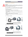
3.1 Solid shaft encoders
Mount the flexible coupling 1 on the encoder shaft;
fix the encoder to the flange 2 (or to the mounting bell) by means
of the screws 3;
secure the flange 2 to the support (or the mounting bell to the
motor);
mount the flexible coupling 1 on the motor shaft;
make sure the alignment tolerances of the flexible coupling 1 are
respected.
3.1.1 Customary installation
a [mm] b [mm] c [mm] d [mm]
AMT58 36 H7 48 - -
3.1.2 Installation using fixing clamps (code LKM-386)
a [mm] b [mm] c [mm] d [mm]
AMT58
36 H7 - 67 -
Page is loading ...
Page is loading ...
Page is loading ...
Page is loading ...
Page is loading ...
Page is loading ...
Page is loading ...
Page is loading ...
Page is loading ...
Page is loading ...
Page is loading ...
Page is loading ...
Page is loading ...
Page is loading ...
Page is loading ...
Page is loading ...
Page is loading ...
Page is loading ...
Page is loading ...
Page is loading ...
Page is loading ...
Page is loading ...
Page is loading ...
Page is loading ...
Page is loading ...
Page is loading ...
Page is loading ...
Page is loading ...
Page is loading ...
Page is loading ...
Page is loading ...
Page is loading ...
Page is loading ...
Page is loading ...
Page is loading ...
Page is loading ...
Page is loading ...
Page is loading ...
Page is loading ...
Page is loading ...
Page is loading ...
Page is loading ...
Page is loading ...
Page is loading ...
Page is loading ...
Page is loading ...
Page is loading ...
Page is loading ...
Page is loading ...
Page is loading ...
Page is loading ...
Page is loading ...
Page is loading ...
Page is loading ...
Page is loading ...
Page is loading ...
Page is loading ...
Page is loading ...
Page is loading ...
Page is loading ...
Page is loading ...
Page is loading ...
Page is loading ...
Page is loading ...
Page is loading ...
Page is loading ...
Page is loading ...
Page is loading ...
Page is loading ...
Page is loading ...
Page is loading ...
Page is loading ...
Page is loading ...
Page is loading ...
Page is loading ...
Page is loading ...
Page is loading ...
Page is loading ...
Page is loading ...
Page is loading ...
Page is loading ...
Page is loading ...
Page is loading ...
Page is loading ...
Page is loading ...
Page is loading ...
Page is loading ...
Page is loading ...
Page is loading ...
Page is loading ...
Page is loading ...
Page is loading ...
Page is loading ...
Page is loading ...
Page is loading ...
Page is loading ...
Page is loading ...
Page is loading ...
Page is loading ...
Page is loading ...
Page is loading ...
Page is loading ...
Page is loading ...
Page is loading ...
Page is loading ...
Page is loading ...
Page is loading ...
Page is loading ...
Page is loading ...
Page is loading ...
Page is loading ...
Page is loading ...
Page is loading ...
Page is loading ...
Page is loading ...
Page is loading ...
Page is loading ...
Page is loading ...
Page is loading ...
Page is loading ...
Page is loading ...
Page is loading ...
Page is loading ...
Page is loading ...
Page is loading ...
-
 1
1
-
 2
2
-
 3
3
-
 4
4
-
 5
5
-
 6
6
-
 7
7
-
 8
8
-
 9
9
-
 10
10
-
 11
11
-
 12
12
-
 13
13
-
 14
14
-
 15
15
-
 16
16
-
 17
17
-
 18
18
-
 19
19
-
 20
20
-
 21
21
-
 22
22
-
 23
23
-
 24
24
-
 25
25
-
 26
26
-
 27
27
-
 28
28
-
 29
29
-
 30
30
-
 31
31
-
 32
32
-
 33
33
-
 34
34
-
 35
35
-
 36
36
-
 37
37
-
 38
38
-
 39
39
-
 40
40
-
 41
41
-
 42
42
-
 43
43
-
 44
44
-
 45
45
-
 46
46
-
 47
47
-
 48
48
-
 49
49
-
 50
50
-
 51
51
-
 52
52
-
 53
53
-
 54
54
-
 55
55
-
 56
56
-
 57
57
-
 58
58
-
 59
59
-
 60
60
-
 61
61
-
 62
62
-
 63
63
-
 64
64
-
 65
65
-
 66
66
-
 67
67
-
 68
68
-
 69
69
-
 70
70
-
 71
71
-
 72
72
-
 73
73
-
 74
74
-
 75
75
-
 76
76
-
 77
77
-
 78
78
-
 79
79
-
 80
80
-
 81
81
-
 82
82
-
 83
83
-
 84
84
-
 85
85
-
 86
86
-
 87
87
-
 88
88
-
 89
89
-
 90
90
-
 91
91
-
 92
92
-
 93
93
-
 94
94
-
 95
95
-
 96
96
-
 97
97
-
 98
98
-
 99
99
-
 100
100
-
 101
101
-
 102
102
-
 103
103
-
 104
104
-
 105
105
-
 106
106
-
 107
107
-
 108
108
-
 109
109
-
 110
110
-
 111
111
-
 112
112
-
 113
113
-
 114
114
-
 115
115
-
 116
116
-
 117
117
-
 118
118
-
 119
119
-
 120
120
-
 121
121
-
 122
122
-
 123
123
-
 124
124
-
 125
125
-
 126
126
-
 127
127
-
 128
128
-
 129
129
-
 130
130
-
 131
131
-
 132
132
-
 133
133
-
 134
134
-
 135
135
-
 136
136
-
 137
137
-
 138
138
-
 139
139
-
 140
140
-
 141
141
-
 142
142
-
 143
143
-
 144
144
-
 145
145


Datalogic AMT58 Owner's manual
- Type
- Owner's manual
- This manual is also suitable for
Ask a question and I''ll find the answer in the document
Finding information in a document is now easier with AI
Related papers
Other documents
-
Baumer EAL580-B - PROFINET Owner's manual
-
-
Baumer HMG10P-T PROFINET Owner's manual
-
Baumer GBAMS Owner's manual
-
HEIDENHAIN PROFINET Interface for Encoders User manual
-
Pepperl+Fuchs ENA58IL-S***-B17 Owner's manual
-
Oriental motor AZD-KRPN User manual
-
Siemens v1.0 User manual
-
SICK AFS/AFM60 PROFINET Absolute Encoder Operating instructions
-
Lika XAC80 PB User manual