Lennox CBA38MV Air Handler User manual
- Category
- Split-system air conditioners
- Type
- User manual
This manual is also suitable for

©2019 Lennox Industries Inc.
Dallas, Texas, USA
Page 1
WARNING
Improper installation, adjustment, alteration, service
or maintenance can cause property damage, personal
injury or loss of life. Installation and service must be
performed by a licensed professional HVAC installer or
equivalent, service agency, or the gas supplier.
IMPORTANT
The Clean Air Act of 1990 bans the intentional venting of
refrigerant (CFCs, HCFCs and HFCs) as of July 1, 1992.
Approved methods of recovery, recycling or reclaiming
must be followed. Fines and/or incarceration may be
levied for noncompliance.
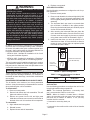
NOTICE
A thermostat is not included and must be ordered
separately.
• A Lennox communicating thermostat must be used in
communicating applications.
• In non-communicating applications, the Lennox
ComfortSense® thermostat may be used, as well as
other non-communicating thermostats.
In all cases, setup is critical to ensure proper system
operation.
Field wiring for both communicating and non-
communicating applications is illustrated in diagrams,
which begin on page 13.
INSTALLATION
INSTRUCTIONS
MULTI-POSITION AIR HANDLERS
507725-02
12/2019
Dave Lennox Signature
®
Collection CBA38MV Units
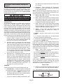
THIS MANUAL MUST BE LEFT WITH THE
HOMEOWNER FOR FUTURE REFERENCE
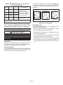
IMPORTANT: Special procedures are required for cleaning the all-aluminum coil in this unit. See page 43 in this instruction
for information.
IMPORTANT INFORMATION FOR INSTALLER
A
B
C
HORIZONTA L DRAIN PAN (SEE
UPFLOW APPLICATIONS ON PAGE
5 AND DOWNFLOW APPLICATIONS
ON PAGE 8 )
BLOWER HOUSING SUPPORT PAD.
REFRIGERANT LINE PLUGS (SEE
BRAZING CONNECTION ON PAGE 9) .
CHECK FOR AND REMOVE THE FOLLOWING ITEMS BEFORE OPERATING UNIT.
H
H
CONFIGURE ELECTRIC HEAT
ECB38
Important Update: The CBA38MV Air Handler Control (AHC) has been enhanced to
automatically configure (set-up) the electric heat when the ECBA38 electric heat harness
is connected to CBA38MV air handler. Manual Configuration of the electric heat using
the push button is no longer required. See page 32.
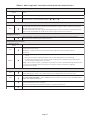
Table of Contents
CBA38MV Upow and Downow Unit Dimensions ....... 2
CBA38MV Horiz. LH/RH Discharge Unit Dimensions ...3
General Information .......................................................4
Shipping and Packing List .............................................4
Installation Clearances ..................................................4
Requirements ................................................................5
Installing the Unit ........................................................... 5
Brazing Connections .....................................................9
Installing the Condensate Drain .................................. 11
Inspecting and Replacing Filters .................................12
Sealing the Unit ...........................................................12
Field Control Wiring .....................................................13
Air Handler Control Button, Display and Jumpers ....... 25
Target CFM Tables ......................................................30
Unit Operating Sequences ..........................................32
Unit Operating Sequences ..........................................34
Heat Pump Operation (Heating and Cooling) ..............39
Cooling Operation ........................................................40
Error Code / Recall Mode ............................................ 41
Indoor Blower Test ....................................................... 42
Operation .....................................................................42
Repairing or Replacing Cabinet Insulation ..................43
Homeowner Maintenance ............................................43
Professional Maintenance ...........................................43

Page 2
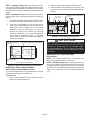
OPTIONAL
ELECTRIC HEAT
(FIELD-INSTALLED)
AIR
FLOW
LIQUID
LINE
SUCTION
LINE
SUPPLY AIR
OPENING
RETURN AIR
FILTER
LOW VOLTAGE
INLETS (TOP AND
RIGHT SIDE)
RETURN AIR
TOP VIEW
FRONT VIEW
SIDE VIEW
BLOWER
PIPING PLAT E DETAIL
(FOR UP-FLOW AND DOWN-FLOW POSITIONS)
A
CB
11‐1/16 (281)
D
F
E
LIQUID LINE
SUCTION LINE
CONDENSATE DRAINS
(2) (HORIZONTAL)
COIL
3/4 (19)
3/4 (19)
5/8 (16)
)52( 1)61( 8/5
5/8 (16)
1‐3/4 (44)
2
(51)
1‐1/8 (29)
4‐3/8 (111)
2‐3/4
(70)
5‐3/8
(137)
3‐1/2 (89)
OPTIONAL
ELECTRIC HEAT
(FIELD-INSTALLED)
AIR FLOW
LIQUID
LINE
SUCTION
LINE
Return
Air Opening
SUPPLY
AIR
FILTER
SUPPLY AIR
TOP VIEW
FRONT VIEW
SIDE VIEW
BLOWER
A
B
C
11‐1/16 (281)
F
D
E
COIL
5/8 (16)
5/8 (16)
5/8 (16)
5/8 (16)
5/8 (16)
LOW VOLTAGE
(RIGHT SIDE)
LINE VOLTAGE
(LEFT SIDE)
DOWN-FLOW POSITION
1 (25)
UP-FLOW POSITION
CONDENSATE DRAINS
(2) (UP-FLOW AND
DOWN-FLOW)
FILTER ACCESS
FILTER ACCESS
H
G
H
G
LINE VOLTAGE
INLETS (TOP
AND LEFT SIDE)
5/8 (16)
5/8 (16)
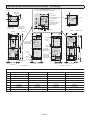
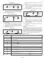
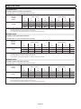
CBA38MV Common Dimensions - Inches (mm)
Dim. -018/024 -030/-036 -042/-048 -060
A
49-1/4 (1251) 51 (1295) 58-1/2 (1486) 62‐1/2 (1588)
B
21-1/4 (540) 21-1/4 (540) 21‐1/4 (540) 21‐1/4 (540)
C
20-5/8 (524) 22‐5/8 (575) 24-5/8 (625) 24-5/8 (625)
D
19-3/4 (502) 19-3/4 (502) 19‐3/4 (502) 19‐3/4 (502)
E
19 (483) 21 (533) 23 (584) 23 (584)
F
20 (508) 20 (508) 20 (508) 20 (508)
G
24-5/8 (625) 26‐3/8 (670) 27‐7/8 (708) 27‐7/8 (708)
H
24-5/8 (625) 24-5/8 (625) 30-5/8 (778) 34‐5/8 (879)
CBA38MV Upow and Downow Unit Dimensions – Inches (mm)

Page 3
LIQUID
LINE
SUCTION
LINE
Supply
Air
Opening
FILTER
LOW VOLTAGE
INLETS (BOTTOM
AND RIGHT
SIDE)
TOP VIEW
FRONT VIEW
BLOWER
H
B
C
D
LIQUID
LINE
SUCTION
LINE
CONDENSATE
DRAINS (2)
(UP-FLOW
AND
DOWN-FLOW)
CONDENSATE
DRAINS (2)
(HORIZONTAL)
Coil
3/4 (19)
3/4 (19)
1‐1/2
(38)
1‐3/4
(44)
5‐3/4
(46)
2
(51)
1‐1/8
(29)
RETURN AIR
OPENING
F
E
5/8 (16)
5/8 (16)
5/8 (16)
END VIEW
AIR
FLOW
OPTIONAL ELECTRIC
HEAT (FIELD-INSTALLED)
11‐1/16
(281)
LINE VOLTAGE
INLETS (TOP
AND RIGHT
SIDE)
5‐3/8
(137)
4‐3/8
(111)
LIQUID
LINE
SUCTION
LINE
Supply
Air Opening
FILTER
LOW VOLTAGE
INLETS (TOP AND
LEFT SIDE)
END VIEW
BLOWER
B
C
D
Coil
3/4 (19)
3/4 (19)
3/4 (19)
Return
Air Opening
F
E
5/8 (16)
5/8 (16)
5/8 (16)
END VIEW
Air Flow
OPTIONAL ELECTRIC
HEAT (FIELD INSTALLED)
LINE VOLTAGE INLETS
(BOTTOM AND LEFT SIDE)
Horizontal Position
(Right‐Hand Air
Discharge)
FILTER ACCESS
FILTER ACCESS
5‐3/4
(146)
1‐1/2 (38)
1‐3/4
(44)
CONDENSATE DRAINS (2)
(HORIZONTA L)
A
5/8 (16)
G
H
A
5/8 (16)
G
1 (25)
1 (25)
11‐1/16
(281)
PIPING PLAT E
DETAIL
LIQUID
LINE
SUCTION LINE
2
(51)
1‐1/8
(29)
5‐3/8
(137)
4‐3/8
(111)
PIPING PLAT E
DETAIL
Horizontal Position
(Left‐Hand Air
Discharge)
TOP VIEW
FRONT VIEW
3/4 (19)
END VIEW
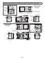
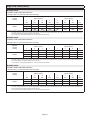
FOR DIMENSIONS “A” THROUGH
“H”, SEE CHART ON PAGE 2.
CBA38MV Horizontal Left- and Right-Hand Discharge Unit Dimensions – Inches (mm)

Page 4
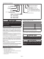
Model Number Identication
Coil Type
A = Aluminum Coil
230CB 38 036-01
Series
Nominal Cooling Capacity
018/024 = 1.5 to 2 tons (5.3 to 7 kW)
030 = 2.5 tons (8.8 kW)
036 = 3 tons (10.6 kW)
048 = 4 tons (14.1 kW)
060 = 5 tons (17.6 kW)
Minor Revision Number
Configuration
MV = Multi-Position, Variable
speed blower motor
-
Voltage
230 = 208/230V-60hz-1ph
--6
Refrigerant Metering Device
2 = Fixed Orifice
3 = TXV - Bleed port (indoor unit)
4 = TXV - Non-bleed port (indoor unit)
5 = TXV - Non-bleed port (outdoor unit)
6 = TXV - R410A Non-bleed port (indoor
unit)
MV
Unit Type
CB = Air Handler
A
042 = 3.5 tons (12.3 kW)
CAUTION
As with any mechanical equipment, contact with sharp
sheet metal edges can result in personal injury. Take
care while handling this equipment and wear gloves and
protective clothing.
General Information
This indoor unit with all-aluminum coil is designed for
installation with optional eld-installed electric heat and a
matched outdoor unit that is charged with HFC-410A re-
frigerant. These units, designed for indoor installation in
multiple positions, are completely assembled for upow
and horizontal right-hand discharge before being shipped
from the factory.
All CBA38MV air handlers are equipped with a factory-in-
stalled, internally mounted check / expansion valve, which
is suitable for use in HFC-410A applications.
This air handler is compatible with the ComfortSense®
non-communicating thermostat and non-communicating
outdoor units. In addition, this unit has the enhanced ca-
pability of communicating with the communicating thermo-
stats and communicating outdoor units using the Lennox
RSBus protocols.
NOTE - For downow or horizontal left-hand air discharge,
certain eld modications are required.
These instructions are intended as a general guide and do
not supersede local or national codes in any way. Consult
authorities having jurisdiction before installation.
Shipping and Packing List
Package 1 of 1 contains:
1 – Assembled air handler unit
1 – Pipe nipple (Sch80, 3/4" I.D. x 5")
1 – Downow shields and foam tapes (required for down-
ow conguration only)
1 – Horizontal drip shield (CBA38MV-060 only)
1 – Warranty card
Check the air handler for shipping damage; if found, im-
mediately contact the last carrier.
Installation Clearances
Cabinet 0 inch (0 mm)
To Plenum 0 inch (0 mm)
To Outlet Duct within 3 feet (914 mm) 0 inch (0 mm)
Floor See Note #1
Service / Maintenance See Note #2
1
Units installed on combustible oors in the downow position with
electric heat require optional downow additive base.
2
Front service access – 24 inches (610 mm) minimum.
NOTE - If cabinet depth is more than 24 inches (610 mm),
allow a minimum of the cabinet depth plus 2 inches (51
mm).
IMPORTANT
This unit must be matched with an indoor coil as
specied in the Lennox Product Specications (EHB).
Coils previously charged with HCFC-22 must be ushed.
WARNING
During blower operation, the ECM motor emits
energy that may interfere with pacemaker operation.
Interference is reduced by both the sheet metal cabinet
and distance.

Page 5
WARNING
Improper installation of the air handler can result in
personal injury or death.
Do not allow external combustion products or other
contaminants to enter the return air system or to be
mixed with air that will be supplied to the living space.
Use sheet metal screws and joint tape or duct mastic to
seal return air system to air handler. In platform
installations, the air handler should be sealed airtight to
the return air plenum. A door must never be used as
a portion of the return air duct system. The base must
provide a stable support and an airtight seal to the air
handler. Allow absolutely no sagging, cracks, gaps. etc.
For no reason should return and supply air duct systems
ever be connected to or from other heating devices
such as a replace or stove. etc. Fire, explosion, carbon
monoxide poisoning, personal injury and/or property
damage could result.
Requirements
In addition to conforming to manufacturer’s installation in-
structions and local municipal building codes, installation
of Lennox air handler units (with or without optional elec-
tric heat), shall conform with the following National Fire
Protection Association (NFPA) standards:
• NFPA No. 90A - Standard for Installation of Air Condi-
tioning and Ventilation Systems
• NFPA No. 90B - Standard for Installation of Residence
Type Warm Air Heating and Air Conditioning Systems
This unit is approved for installation clearance to combus-
tible material as stated on the unit rating plate. Accessi-
bility and service clearances must take precedence over
combustible material clearances.
Installing the Unit
These units are factory-congured for upow and hori-
zontal right-hand discharge installation. For downow or
horizontal left-hand discharge, certain eld modications
are required.
DISASSEMBLE/REASSEMBLE AIR HANDLER UNITS
The air handler units consists of two factory-assembled
sections. It may be necessary to disassemble the sections
when positioning the unit for installation.
To disassemble:
1 - Remove access panels.
2 - Remove both blower and coil assemblies. This will
lighten the cabinet for lifting.
3 - Remove one screw from the left and right posts
inside the unit. Remove one screw from each side on
the back of the unit. Unit sections will now separate.
To reassemble:
1 - Align cabinet sections together.
2 - Reinstall screws.
3 - Replace blower and coil assemblies.
4 - Replace access panel.
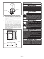
UPFLOW APPLICATION
Use the following procedures to congure the unit for up-
ow operations:
1 - Remove access panels.
2 - Remove and discard the horizontal drip shield (-060
model, used only on horizontal applications) and
the corrugated padding between the blower and coil
assembly.
3 - The horizontal drain pan must be removed when
the coil blower is installed in the upow position.
Removing the horizontal drain pain will allow proper
air ow and increased eciency.
4 - After removing the horizontal drain pan, place the
unit in the desired location. Set unit so that it is level.
Connect return and supply air plenums as required
using sheet metal screws as illustrated in gure 1.
5 - Install units that have no return air plenum on a
stand that is at least 14" from the oor to allow for
proper air return. Lennox oers an optional upow
unit stand as listed in table 1.
HORIZONTAL DRAIN PAN
(MUST BE REMOVED)
UP-FLOW /
DOWN-FLOW
DRAIN PAN
FIGURE 1. Upow Conguration
TABLE 1. Optional Side-Return Unit Stand
(Upow Only)
Model Kit Number
All unit sizes
45K32
HORIZONTAL RIGHT-HAND DISCHARGE
APPLICATION
Use the following procedures to congure the unit for hor-
izontal right-hand discharge operations:
NOTE – For horizontal applications, a secondary drain
pan is recommended. Refer to local codes.
NOTE – When air handler is located above a nished
space, the secondary drain pan must have a larger foot-
print than the air handler. In addition, a 3/4" (19.1mm)
overow drain line must be:
• Connected to secondary drain pan
or
• Connected to the overow drain outlet of the air handler
drain pan.

Page 6
NOTE - (-060 Model Only) Before operating the unit, re-
move access panels and the horizontal drip shield and the
corrugated padding between the blower and coil assem-
bly. Discard the corrugated padding and the downow drip
shields.
NOTE - (-060 Model Only) Install the horizontal shield on
the front edge of the horizontal drain pan as illustrated in
gure 2.
1 - No further adjustment is necessary. Set unit so that it
is sloped 1/4" towards the drain pan end of the unit.
2 - If the unit is suspended, the entire length of the
cabinet must be supported. If you use a chain or
strap, use a piece of angle iron or sheet metal
attached to the unit (either above or below) to
support the length of the cabinet. Use securing
screws no longer than 1/2" to avoid damaging the
coil or lter as illustrated in gure 3. Use sheet
metal screws to connect the return and supply air
plenums as required.
UP-FLOW / DOWN-FLOW
DRAIN
PAN
HORIZONTAL DRIP SHIELD (-060 MODELS)
DOWN-FLOW RAIL
HORIZONT
AL DRAIN
PA
N
NO ADJUSTMENT IS NECESSARY
FIGURE 2. Right-Hand Discharge Conguration
HORIZONTAL RIGHT-HAND DISCHARGE
APPLICATION IN HIGH-HUMIDITY AREAS
For horizontal applications in high humidity areas, remove
the downow rail closest to the drain pan.
To remove rail:
1 - Remove the screws from the rail at the back of unit
and at the cabinet support rail.
2 - Remove the downow rail then replace screws.
3 - Seal around the exiting drain pipe, liquid line, and
suction line to prevent humid air from inltrating into
the unit.
FRONT VIEW END VIEW
ANGLE IRON OR
SHEET METAL
ELECTRICAL INLET CLEARANCE 4"
(102 mm)
1/2" SCREWS MAXIMUM
FIGURE 3. Suspending Horizontal Unit
IMPORTANT
When removing the coil, there is possible danger of
equipment damage and personal injury. Be careful when
removing the coil assembly from a unit installed in right-
or left-hand applications. The coil may tip into the drain
pan once it is clear of the cabinet. Support the coil when
removing it.
HORIZONTAL LEFT-HAND DISCHARGE
APPLICATION
NOTE – For horizontal applications, a secondary drain
pan is recommended. Refer to local codes.
NOTE - (-060 Model Only) Before operating the unit, re-
move access panels and the horizontal drip shield and the
corrugated padding between the blower and coil assem-
bly. Discard the corrugated padding and the downow drip
shields. (The shields are used for downow applications
only.)

Page 7
HORIZONTAL DRIP SHIELD (-060 MODEL)
DOWN-FLOW RAIL FRONT EDGE OF HORIZONTAL
DRAIN PAN
FIGURE 5. Left-Hand Discharge Conguration
8 - Install the horizontal shield (-060 model) on the
front edge of the horizontal drain pan as illustrated
in gure 5.
NOTE – For horizontal applications in high humidity ar-
eas, remove the downow rail closest to the drain pan. To
remove rail, remove screw from rail at back of unit and at
cabinet support rail. Remove downow rail then replace
screws. Also, seal around the exiting drain pipe, liquid and
suction lines to prevent inltration of humid air.
9 - Knock out drain seal plate from access door. Secure
plate to cabinet front ange with screw provided.
10 - Flip access door and replace it on the unit.
11 - Set unit so that it is sloped 1/4ʺ toward the drain
pan end of the unit. Connect return and supply air
plenums as required using sheet metal screws.
90º
BEND
CABINET
SUPPORT
COIL SHOWN IN UPFLOW POSITION FOR EASY
CONVERSION (LEFT-HAND AIR DISCHARGE )
TOP CAP
SCREWS
DRAIN PAN
REINSTALLED
HERE
DRAIN PAN
SHIPPING
LOCATION
TOP CAP ROTATED TO
CORRECT POSITION
———— DRAIN PLUGS ————
REINSTALLED HERE REMOVED FROM HERE
BACK COIL
END SEAL
TOP CAP
90º
BEND
INSTALL DRAIN PAN
BETWEEN TAB AND
EXTERIOR INNER WALL.
DETAIL A
DETAIL B
DETAIL C
HORIZONTA L DRIP
SHIELD SCREW
(FRONT COIL END
SEAL)
FRONT VIEW
3/16” PLASTIC
PLUG (REAR COIL
END SEAL)
ALIGN HOLES WITH
HOLES IN COIL END
PLATE. STARTING WITH
THE ROUND HOLES ON
THIS END.
FIGURE 4. Field Modication for Left-Hand Discharge
Use the following procedures to congure the unit for hor-
izontal left-hand discharge operations:
1 - Pull the coil assembly from unit. Pull o the horizontal
drain pan.
2 - Remove the drain plugs from back drain holes on
horizontal drain pan and reinstall them on front
holes.
IMPORTANT
After removal of drain pan plug(s), check drain hole(s)
to verify that drain opening is fully open and free of any
debris. Also check to make sure that no debris has fallen
into the drain pan during installation that may plug up the
drain opening.
3 - Rotate drain pan 180º front-to-back and install it on
the opposite side of the coil.
4 - Remove screws from top cap. Remove horizontal
drip shield screw located in the center of the back
coil end seal as illustrated in gure 4 on page 5.
5 - Rotate horizontal drip shield 180º front-to-back.
6 - Remove plastic plug from left hole on coil front
end seal and reinstall plug in back hole. Reinstall
horizontal drip shield screw in front coil end seal.
Drip shield should drain downward into horizontal
drain pan inside coil.
NOTE – Be very careful when reinstalling the screws into
the coil end plate engaging holes. Misaligned screws may
damage the coil.
7 - From the upow position, ip cabinet 90º to the
left and set into place. Replace blower assembly.
Secure coil in place by bending down the tab on the
cabinet support rail as illustrated in gures 4 and 5.

Page 8
HORIZONTA L DRAIN P
AN
(REMOVE FROM UNIT)
UP-LOAD /
DOWNFLO
W
DRAIN PAN
FIGURE 6. Downow Discharge Position
SIDE
VIEW
2” WIDE FOAM TAPE
DRIP SHIELD
1” WIDE FOAM TAPE (LONGER PIECE)
FIGURE 7. Applying Foam Tape to Drip Shield
COIL
DRIP SHIELD
DRIP PAN
FIGURE 8. Downow Drip Shields
6 - Replace the coil assembly and blower if you have
removed it. Replace the coil access panel.
7 - Set the unit so that it is level. Using sheet metal
screws, connect the return and supply air plenums
as required.
NOTE - For downow application, metal or Class I supply
and return air plenums must be used.
12 - If suspending the unit, it must be supported along the
entire length of the cabinet. If using chain or strap,
use a piece of angle iron or sheet metal attached
to the unit (either above or below) so that the full
length of the cabinet is supported. Use securing
screws no longer than 1/2ʺ to avoid damage to coil
or lter, as illustrated in gure 3 on page 6. Connect
return and supply air plenums as required using
sheet metal screws.
DOWNFLOW APPLICATION
Use the following procedures to congure the unit for
downow operations:
IMPORTANT
If electric heat section with circuit breakers (ECB29/
ECB31) is installed in a CBA38MV unit in a downow
application, the circuit breakers must be rotated 180°
to the UP position. See ECB29/ECB31 installation
instructions for more details.
Table 2 outlines the sizes of the various drip shields.
NOTE - (-060 Model Only) Remove access panels and
horizontal drip shield from the corrugated padding be-
tween the blower and coil assembly.
1 - Remove the coil assembly from the unit.
2 - For best eciency and air ow, remove the
horizontal drain pan from the units in downow
positions as illustrated in gure 6.
3 - Rotate cabinet 180º from the upright position. See
gure 6. You may need to rst remove the blower
assembly to lighten the cabinet for lifting.
4 - Foam tape that is provided creates a seal between
the drip shield and the coil so that water does not
leak into the air stream. The foam tape pieces
are precut. Apply the tape to the drip shields as
illustrated in gure 7 and specied as follows:
• Apply two pieces of foam tape provided down both
ends of each shield. The tape should measure
4-3/4ʺ X 2ʺ (120 X 25 mm). Ensure that the tape
covers both sides of the shield equally.
• Apply the longer piece of 1 inch wide foam tape be-
tween the end pieces of tape.
5 - From the underside of the coil, install the downow
drip shield rmly in place as illustrated in gure 8.
TABLE 2. Downow Drip Shields (Tape Required)
Units Length Width
-018/024 Not Required Not Required
-030 15-7/8ʺ 4-11/16ʺ
-036, -042 17-7/8ʺ 4-11/16ʺ
-048, -060 19-7/8ʺ 4-11/16ʺ

Page 9
COMBUSTIBLE FLOOR
ADDITIVE BASE
PROPERLY SIZED
FLOOR OPENING
AIR
HANDER
UNIT
FIGURE 9. Downow Combustible Flooring Base
8 - For downow installation on combustible ooring,
an additive base must be used as illustrated in gure
9 on page 9. See CBA38MV Product Specications
(EHB) for downow combustible ooring base kits
available for this air handler.
9 - Cut an opening appropriately sized for combustible
base. Base dimensions are illustrated in gure 10.
After opening has been cut, set the additive base
into opening. Connect outlet air plenum to the
additive base. Set the unit on the additive base so
anges of the unit drop into the base opening and
seal against the insulation strips. The unit is now
locked in place. Install return air plenum and secure
with sheet metal screws.
TOP VIEW
OPENING
1‐5/8 (41)
SIDE VIEW
1‐5/8 (41)
11‐3/8
(289)
3 (76)
1‐5/8 (41)
22‐5/8 (575) -018/024
24‐5/8 (625) -030, 036
26‐5/8 (676) -042, 048, 060
5/8 (16)
13‐1/2 (343)
SUPPLY AIR OPENING
INCHES (MM)
23-1/4 (591)
20 (508)
FIGURE 10. Downow Combustible Base Dimensions
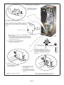
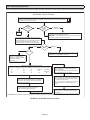
Brazing Connections
WARNING
Polyol ester (POE) oils used with HFC-410A refrigerant
absorb moisture very quickly. It is very important that the
refrigerant system be kept closed as much as possible.
DO NOT remove line set caps or service valve stub caps
until you are ready to make connections.
WARNING
Danger of re. Bleeding the refrigerant
charge from only the high side may result
in pressurization of the low side shell and
suction tubing. Application of a brazing torch
to a pressurized system may result in ignition
of the refrigerant and oil mixture. Check the
high and low pressures before applying heat.
WARNING
Danger of explosion!
Can cause equipment damage, injury, or
death.
When using a high pressure gas such as
nitrogen to pressurize a refrigeration or air
conditioning system, use a regulator that can
control the pressure down to 1 or 2 psig (6.9
to 13.8 kPa).
CAUTION
Brazing alloys and ux contain materials which are
hazardous to your health.
Avoid breathing vapors or fumes from brazing operations.
Perform operations only in well ventilated areas.
Wear gloves and protective goggles or face shield to
protect against burns.
Wash hands with soap and water after handling brazing
alloys and ux.
IMPORTANT
To prevent the build-up of high levels of nitrogen when
purging, it must be done in a well-ventilated area. Purge
low-pressure nitrogen (1 to 2 psig) through the refrigerant
piping during brazing. This will help to prevent oxidation
and the introduction of moisture into the system.

Page 10
REMOVE ACCESS PANEL
A
REMOVE RUBBER PLUG FROM BOTH LIQUID
AND SUCTION LINES
B
USE A WET RAG TO PROTECT CTXV
SENSING BULB WHEN BRAZING
SUCTION LINE CONNECTIONS.
C
NITROGEN
HIGH
LOW
EITHER REMOVE OR PUSH PIPE WRAPPING BACK
THROUGH HOLE IN PIPING PLATE BEFORE LINE
SET CONNECTION AND BRAZING.
D
E
CONNECT PIPES
F
CONNECT GAUGES AND
START NITROGEN FLOW
G
PLACE A WET RAG AGAINST PIPING
PLATE AND AROUND THE SUCTION
LINE CONNECTION. A
H
BRAZE CONNECTION. ALLOW PIPE TO
COOL BEFORE REMOVING WET RAG
FROM CTXV SENSING BULB AND PIPING
PANEL AREA.
I
REPEAT PREVIOUS PROCEDURE FOR LIQUID
LINE.
NOTE — REFER TO OUTDOOR UNIT INSTALLATION INSTRUCTIONS
FOR REFRIGERANT PIPING SIZE REQUIREMENTS .
NOTE — REFRIGERANT LINE SETS
SHOULD BE ROUTED TO ALLOW
FILTER ACCESSIBILITY.
NOTE — CBA38MV SERIES UNITS USE NITROGEN OR DRY AIR
AS A HOLDING CHARGE. IF THERE IS NO PRESSURE WHEN
THE RUBBER PLUGS ARE REMOVED, CHECK THE COIL FOR
LEAKS BEFORE INSTALLING.
REFER TO INSTRUCTIONS PROVIDED WITH OUTDOOR UNIT FOR
LEAK TESTING, EVACUATING AND CHARGING PROCEDURES
FLOW REGULATED NITROGEN (AT 1 TO 2 PSIG)
THROUGH THE REFRIGERATION GAUGE SET INTO THE
VALVE STEM PORT CONNECTION ON THE OUTDOOR
UNIT LIQUID LINE SER VICE VALVE AND OUT OF THE
VALVE STEM PORT CONNECTION ON THE SUCTION
SERVICE VALVE.
PIPING
PLATE
NOTE - Use silver alloy brazing rods with five or six percent
minimum silver alloy for copper-to-copper brazing, 45
percent alloy for copper-to-brass and copper-to-steel
brazing.
PLEASE READ IMPORTANT ISSUES CONCERNING BRAZING
OPERATIONS ON PAGE 10 BEFORE PROCEEDING.
FIGURE 11. Brazing Connections

Page 11
TABLE 3. CBA38MV Refrigerant Connections and
Line Set Requirements
Model
Liquid
Line
Vapor
Line
L15 Line Sets
-018/
024
3/8ʺ
(10mm)
3/4ʺ
(19mm)
L15 line set sizes are
dependant on unit
match-up. See Product
Specications (EHB) for
outdoor unit to determine
correct line set sizes
-030
-036
3/8ʺ
(10mm)
3/4ʺ
(19mm)
-042
-048
3/8ʺ
(10mm)
7/8"
(22mm)
-060
3/8ʺ
(10mm)
7/8"
(22mm)
Field fabricated
NOTE - Some applications may require a eld-provided 7/8ʺ
to 1-1/8ʺ adapter.
NOTE - When installing refrigerant lines longer than 50
feet, see the Lennox Refrigerant Piping Design and Fab-
rication Guidelines, CORP. 9351-L9, or contact Lennox
Technical Support Product Applications for assistance.
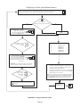
Installing the Condensate Drain
IMPORTANT
After removal of drain pan plug(s), check drain hole(s)
to verify that drain opening is fully open and free of any
debris. Also check to make sure that no debris has fallen
into the drain pan during installation that may plug up the
drain opening.
MAIN DRAIN
Connect the main drain and route downward to drain line
or sump. Do not connect drain to a closed waste system.
See Figure 13 for typical drain trap conguration.
OVERFLOW DRAIN
It is recommended that the overow drain is connected to
an overow drain line for all units. If overow drain is not
connected, it must be plugged with provided cap.
For downow orientation, the overow drain MUST be
connected and routed to a overow drain line. See Fig-
ure 12 for main and overow drain locations based on coil
orientation.
LEFT-HAND AIR
DISCHARGE
MAIN DRAIN ON
RIGHT
OVERFLOW
DRAIN ON LEFT
UP-FLOW OR
DOWN-FLOW
RIGHT-HAND AIR
DISCHARGE
FIGURE 12. Main and Overow Drain Locations
Based on Coil Orientation
BEST PRACTICES
The following best practices are recommended for the
condensate removal process:
• Main and overow drain lines should NOT be smaller
than both drain connections at drain pan.
• Overow drain line should run to an area where home-
owner will notice drainage.
• It is recommended that the overow drain line be vented
and a trap installed. Refer to local codes.
• Condensate drain lines must be congured or provided
with a cleanout to permit the clearing of blockages and
for maintenance without requiring the drain line to be
cut.

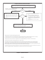
Page 12
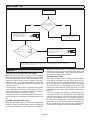
ABOVE
FINISHED
SPACE?
OVERFLOW DRAIN LINE
ALWAYS RUN AN OVERFLOW DRAIN LINE. IF NOT POSSIBLE TO
ROUTE OVERFLOW DRAIN LINE, INSTALL LOW VOLTAGE
OVERFLOW SWITCH KIT. WIRE KIT TO SHUT DOWN
COMPRESSOR PER INSTRUCTIONS.
NO
YES
LENNOX #
X3169
CLEAN OUT
VENT
PRESS IN
(DO NOT GLUE)
VENT MUST EXTEND
ABOVE HEIGHT OF
COIL DRAIN PAN BY
TWO INCHES (51MM)
1” X 3/4” X 3/4”
REDUCING
TEE WITH
PLUG
LENNOX
1
P-TRAP
49P66, J-TRAP #
91P90 OR ANY
PVC SCH 40 P- OR
J-TRAP 3/4”
OVERFLOW
DRAIN
AIR HANDLER DRAIN PAN
WHEN A COIL IS LOCATED ABOVE A FINISHED SPACE, A
3/4” (19.1MM) SECONDARY DRAIN LINE MUST BE:
CONNECTED TO SECONDARY DRAIN PAN
OR
CONNECTED TO THE OVERFLOW DRAIN OUTLET OF
THE AIR HANDLER DRAIN PAN.
TRAPS MUST BE DEEP ENOUGH TO OFFSET MAXIMUM STATIC DIFFERENCES —
GENERALLY, TWO INCHES (51MM).
DRAIN LINE SHOULD
SLOPE A MINIMUM OF
ONE INCH PER 10
FEET (25MM PER 3
METERS)
NOTE — WHEN A AIR HANDLER IS LOCATED
ABOVE A FINISHED SPACE THE SECONDARY
DRAIN PAN MUST HAVE A LARGER FOOTPRINT
THAN THE AIR HANDLER.
MAIN
DRAIN
TO APPROVED
DRAIN
FOR NEGATIVE PRESSURE COILS (BLOWER
AFTER COIL) TRAPS ARE REQUIRED ON ALL
DRAIN LINES CONNECTED TO COIL.
COMPACT OVERFLOW SWITCH WITH 3/4” FEMALE SLIP INLET
AND MALE ADAPTER, TWO PART DESIGN FOR USE WHERE
OBSTRUCTIONS PREVENT DIRECT THREADING
SECONDARY
DRAIN PAN
2”
(51MM)
TRAP DEPTH
1
LENNOX P-TRAP 49P66 REQUIRES A LARGER INSTALLATION SPACE THAN THE J-TRAP 91P90.
2
PIPE NIPPLE PROVIDED IN BAG ASSEMBLY - SCH 80, 3/4” I. D. X 5” - 34K7401 (1): CUT THE PIPE IN HALF AND USE IT TO ROUTE THE MAIN DRAIN.
MAIN
DRAIN
PROVIDED
PIPE NIPPLE
2
CUT TO
REQUIRED
LENGTH
SIDE VIEW
FIGURE 13. Typical Main and Overow Drain Installations
Inspecting and Replacing Filters
IMPORTANT
Filter access door must be in place during unit operation.
Excessive warm air entering the unit from unconditioned
space may result in water blow-o problems.
Filters may be duct-mounted or installed in the cabinet. A
lter is installed at the factory. Note that lter access door
ts over access panel. Air will leak if the access panel is
placed over the lter door.
Filters should be inspected monthly and must be cleaned
or replaced when dirty to assure proper furnace operation.
To replace lter:
1 - Loosen the thumbscrews holding the lter panel in
place.
2 - Slide the lter out of the guides on either side of
cabinet.
3 - Insert new lter.
4 - Replace panel.
See table 4 for replacement lter sizes.
TABLE 4. Filter Dimensions
CBA38MV Filter Size – In. (mm)
-018/024, -030, -036 20 x 20 x 1 (508 x 508 x 25)
-042, -048, -060 20 x 24 x 1 (508 x 610 x 25)
Sealing the Unit
WARNING
There must be an airtight seal between the bottom of
the air handler and the return air plenum. Use berglass
sealing strips, caulking, or equivalent sealing method
between the plenum and the air handler cabinet to
ensure a tight seal. Return air must not be drawn from a
room where this air handler or any gas-fueled appliance
(i.e., water heater), or carbon monoxide-producing
device (i.e., wood replace) is installed.
Seal the unit so that warm air is not allowed into the cabi-
net. Warm air introduces moisture, which results in water
blow-o problems. This is especially important when the
unit is installed in an unconditioned area.

Page 13
Make sure the liquid line and suction line entry points are
sealed with either the provided exible elastomeric ther-
mal insulation, or eld provided material (e.g. Armaex,
Permagum or equivalent). Any of the previously men-
tioned materials may be used to seal around the main and
auxiliary drains, and around open areas of electrical inlets.
Field Control Wiring
WARNING
Electric Shock Hazard.
Can cause injury or death.
Foil-faced insulation has conductive characteristics
similar to metal. Be sure there are no electrical
connections within a ½ʺ of the insulation. If the foil-faced
insulation comes in contact with electrical voltage, the
foil could provide a path for current to pass through to
the outer metal cabinet. While the current produced
may not be enough to trip existing electrical safety
devices (e.g. fuses or circuit breakers), the current can
be enough to cause an electric shock hazard that could
cause personal injury or death.
Wiring must conform to the current National Electric Code
ANSI/NFPA No. 70, or Canadian Electric Code Part I, CSA
Standard C22.1, and local building codes. Refer to follow-
ing wiring diagrams. See unit nameplate for minimum cir-
cuit ampacity and maximum over-current protection size.
WARNING
Run 24V Class II wiring only through specied low
voltage opening. Run line voltage wiring only through
specied high voltage opening. Do not combine voltage
in one opening
Select the proper supply circuit conductors in accordance
with tables 310-16 and 310-17 in the National Electric
Code, ANSI/NFPA No. 70 or tables 1 through 4 in the Ca-
nadian Electric Code, Part I, CSA Standard C22.1.
Separate openings have been provided for 24V low volt-
age and line voltage. Refer to the dimension illustration of
specic location.
CAUTION
USE COPPER CONDUCTORS ONLY.
WIRING CONNECTIONS
1 - Install line voltage power supply to unit from a
properly installed circuit breaker.
2 - Ground unit at unit disconnect switch or to an earth
ground.
NOTE – Connect conduit to the unit using a proper con-
duit tting. Units are approved for use only with copper
conductors. A complete unit wiring diagram is located on
the back side of the unit’s access panel.
3 - Install low voltage wiring from outdoor to indoor unit
and from thermostat to indoor unit.
NOTE – For proper voltages, select thermostat wire gauge
per the following chart:
CAUTION
ELECTROSTATIC
DISCHARGE
(ESD)
Precautions and
Procedures
Electrostatic discharge can aect
electronic components. Take care
during unit installation and service to
protect the unit’s electronic controls.
Precautions will help to avoid
control exposure to electrostatic
discharge by putting the unit, the
control and the technician at the
same electrostatic potential. Touch
hand and all tools on an unpainted
unit surface before performing any
service procedure to neutralize
electrostatic charge.

Page 14
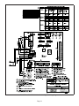
Cut Size: 7" wide x 10" tall
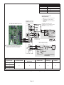
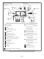
FIGURE 14. CBA38MV Air Handler Unit Typical Wiring Diagram

Page 15
SENSOR
(CENTER SIDE-T0 -SIDE)
9-PIN
CONNECTOR
SECURING
SCREWS
AIR
HANDLER
CONTROL
AIR HANDLER CONTROL
L-BRACKET MOUNTING PLATE
19 IN.
(483 MM)
5-1/2 IN.
(140 MM)
9-PIN CONNECTOR
ELECTRIC HEAT RELAY
PART NO. 49W91
22V DIRECT CURRENT COIL
30 AMP CONTACT RATING
FASTEN THE PROBE
BRACKET TO THE
PLENUM WITH TWO
SELF-TAPPING SHEET
METAL SCREWS.
CONNECT WIRES TO DISCHARGE AIR SENSOR
TERMINAL ON AIR HANDLER CONTROL.
PLENUM
CBA38MV AIR HANDLER CONTROL
PART NO. 16X40
DISCHARGE SENSOR
(DAT)
TEMPRESISTANCE
ºF (OHMS)
30 34,566
40 26,106
50 19,904
60 15,313
70 11,884
80 9,298
90 7,332
100 5,826
DETAIL A
NOTE — EVENHEAT MODE CANNOT BE ENABLED WITH
HARMONY III
DUE TO EACH CONTROL REQUIRING ITS OWN
DISCHARGE AIR SENSOR.
THE AIR HANDLER CONTROL (AHC) HAS
TWO SCREW TERMINALS MARKED
DISCHARGE AIR SENSOR. THE SENSOR
IS REQUIRED FOR EVENHEAT
OPERATION, IS FIELD-MOUNTED AND
MUST BE ORDERED SEPARATELY
(CATALOG # 88K38).
DETAIL B
TEMPERATURE RESISTANCE
CHART
NOTE - Due to varying duct designs
and air flow conditions, relocation of
the discharge sensor may be required
to insure accurate sensing.
FIGURE 15. Component Connections

Page 16
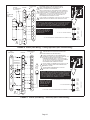
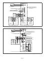
AIR HANDLER CONTROL COMES FROM FACTORY WITH A
METAL JUMPER BETWEEN W1 TO W2 AND W2 TO W3. SEE
FIGURE 21 FOR HEAT SECTION CONFIGURATION.
CUT ON-BOARD JUMPER R-DS WHEN DEHUMIDIFICATION TERMINAL IS USED.
CBA38MV
COMFORTSENSE
7500
AIR
CONDITIONER
UNIT
(TWO-STAGE)
RED
YELLOW
BLUE
BLACK
1
1
R
W3
W2
W1
O
Y1
Y2
G
DS
C
R
H
W2
W1
O
Y1
Y2
G
D
B
C
Y1-Y2
2-STAGE
COMPR
R-O
HEAT
PUMP
R-DS
DEHUM
OR
HARMONY
CUT FOR OPTION
CUT ON-BOARD JUMPER Y1-Y2 FOR TWO-STAGE AC
DO NOT CUT ON-BOARD JUMPER R -O.
IMPORTANT – USE CARE WHEN
CUTTING OPTION JUMPERS. SEE
JUMPER AND LINK GUIDE FOR
FURTHER DETAILS.
AIR HANDLER
CONTROL
OPTIONAL
N.C. CONDENSATE
FLOAT SWITCH
FLOAT SW
WHEN A CONVENTIONAL 24V NON-COMMUNICATING THERMOSTAT
IS USED WITH THE CBA38 AIR HANDLER, THE FLOAT SWITCH MUST
BE WIRED TO BREAK "Y1 COMPRESSOR DEMAND" WIRE TO THE
OUTDOOR UNIT. A FLOAT SWITCH CONNECTED TO "FLOAT SW"
TERMINALS WILL NOT SHUT OFF THE COOLING WHEN A 24V
NON-COMMUNICATING THERMOSTAT IS USED
IMPORTANT – WHEN A CONVENTIONAL 24V NON-COMMUNICATING THERMOSTAT
IS USED WITH THE CBA38 AIR HANDLER, THE FLOAT SWITCH MUST BE WIRED TO
BREAK "Y1 COMPRESSOR DEMAND" WIRE TO THE OUTDOOR UNIT. A FLOAT
SWITCH CONNECTED TO "FLOAT SW" TERMINALS WILL NOT SHUT OFF THE
COOLING WHEN A 24V NON-COMMUNICATING THERMOSTAT IS USED.
3
3
2
DO NOT CONNECT A CONDENSATE FLOAT SWITCH TO THE "FLOAT SW"
TERMINAL WHEN A NON-COMMUNICATING THERMOSTAT IS USED
FIGURE 16. Control (Field Wiring) – Cooling Application (Non-Communicating)
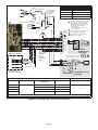
HEAT PUMP
UNIT
(TWO-STAGE)
X2658 OUTDOOR SENSOR IS REQUIRED FOR OUTDOOR
TEMPERATURE DISPLAY, DEW POINT CONTROL, HEAT
PUMP AND DUAL FUEL BALANCE POINTS.
COMFORTSENSE
7500
R
R
W3
H
W2
W2
W1
W1 W1
O
OO
Y1
Y1
Y1
Y2Y2
G
G
C
C
T
T
D
B
Y2
DS
O. D.
SENSOR
(X2658)
Y2
OUT
BL
1
1
CUT ON-BOARD JUMPER R -O.
CUT ON-BOARD JUMPER R-DS WHEN DEHUMIDIFICATION TERMINAL IS USED.
CUT ON-BOARD JUMPER Y1-Y2 FOR TWO-STAGE HP
2
FIELD PROVIDED JUMPER BETWEEN Y2 OUT BL ON
HEAT PUMP TO Y2 ON CBA38MV.
Y1-Y2
2-STAGE
COMPR
R-O
HEAT
PUMP
R-DS
DEHUM
OR
HARMONY
CUT FOR OPTION
CBA38MV
IMPORTANT – USE CARE
WHEN CUTTING OPTION
JUMPERS. SEE JUMPER
AND LINK GUIDE FOR
FURTHER DETAILS.
OPTIONAL N.C.
CONDENSATE
FLOAT SWITCH
C
R
FLOAT SW
3
2
4
WHEN A CONVENTIONAL 24V NON-COMMUNICATING
THERMOSTAT IS USED WITH THE CBA38 AIR HANDLER, THE
FLOAT SWITCH MUST BE WIRED TO BREAK "Y1
COMPRESSOR DEMAND" WIRE TO THE OUTDOOR UNIT.
A FLOAT SWITCH CONNECTED TO "FLOAT SW" TERMINALS
WILL NOT SHUT OFF THE COOLING WHEN A 24V
NON-COMMUNICATING THERMOSTAT IS USED.
3
4
DO NOT CONNECT A CONDENSATE FLOAT SWITCH TO THE
"FLOAT SW" TERMINAL WHEN A NON-COMMUNICATING
THERMOSTAT IS USED.
IMPORTANT – WHEN A CONVENTIONAL 24V NON-COMMUNICATING
THERMOSTAT IS USED WITH THE CBA38 AIR HANDLER, THE FLOAT
SWITCH MUST BE WIRED TO BREAK "Y1 COMPRESSOR DEMAND"
WIRE TO THE OUTDOOR UNIT. A FLOAT SWITCH CONNECTED TO
"FLOAT SW" TERMINALS WILL NOT SHUT OFF THE COOLING WHEN
A 24V NON-COMMUNICATING THERMOSTAT IS USED.
FIGURE 17. Control (Field Wiring) – Heat Pump (Non-Communicating)

Page 17
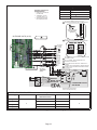
iComfort
®
AIR
HANDLER (AHC)
S30 SMART HUB
IComfort
®
OUTDOOR UNIT
(AC OR HP)
C
i+
i-
R
S30 MAG
MOUNT
OPTIONAL DISCHARGE AIR
SENSOR (SEE DAS NOTE ON
PAGE 7)
SOR (SEE OAS NOTE ON PAGE
7)
12VDC
+ -
COM
BUS
A B
COM
BUS
B A
12VDC
- +
ALL CONNECTIONS ON THE RSBUS ARE LIMITED TO 1500FT. WIRE GAUGE OF RSBUS WIRE IS 18.
N.C. CONDENSATE
FLOAT SWITCH
FLOAT SW
SW
R
1
1
REMOVE FACTORY-INSTALLED
JUMPER ON FLOAT SWITCH
TERMINALS WHEN INSTALLING
A FLOAT SWITCH
FIGURE 18. iComfort
®
Communicating System Wiring
A
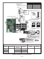
LL CONNECTIONS ON THE RSBUS IS LIMITED TO 1500FT. WIRE GAUGE OF RSBUS WIRE IS 18.
24VAC
HEAT PUMP UNIT
- 1 OR 2 STAGE
iComfort
®
DLER (AHC)
OPTIONAL OUTDOOR
AIR SENSOR (SEE OAS
NOTE ON PAGE 7)
OPTIONAL DISCHARGE AIR SENSOR
(SEE DAS NOTE ON PAGE 7)
SETUP NOTES:
CUT Y1-Y2 ON-BOARD
MUNICATING)
CUT R-O ON-BOARD JUMPER
FOR OUTDOOR HEAT
MUNICATING)
COM
BUS
B A
12VDC
- +
12VDC
+ -
COM
BUS
A B
S30 MAG
MOUNT
S30 SMART
HUB
N.C. CONDENSATE
FLOAT SWITCH
FLOAT SW
SW
R
1
1
REMOVE FACTORY-INSTALLED
JUMPER ON FLOAT SWITCH
TERMINALS WHEN INSTALLING
A FLOAT SWITCH
JUMPER FOR 2-STAGE OUT-
FIGURE 19. iComfort
®
Communicating Indoor / Non-Communicating Outdoor (HP) System Wiring

Page 18
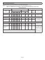
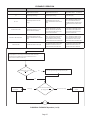
Components
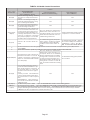
Unit Type
Thermostat ComfortSense® 7000 or 7500
Indoor Conventional 24V
Outdoor Conventional 24V
NUMBER OF WIRES REQUIRED—Indoor unit to: Thermostat to:
System type Humiditrol
®
EDA Comfort Sense 7000 or 7500
Thermostats
Outdoor Unit Outdoor Air Sensor
1 stage AC
3
7* 3
2
2 stage AC 8* 4
1 stage HP 8* 5
2 stage HP 9* 6
*Includes conductor for 2-stage heat
B4
FAN
Blue
Yellow
Black
K1
FIRST,
CUT YELLOW WIRE HERE.
*OUTDOOR RELAY —
NOT REQUIRED WITH
SINGLE‐SPEED
OUTDOOR FAN
Purple
Yellow
Yellow
2
SECOND,
REWIRE YELLOW WIRE AS SHOWN
75
ComfortSense 7000 or
7500 Thermostat
OUTDOOR
SENSOR
(X2658)
K1
XP19-024 UNITS COME FACTORY WIRED
FOR LOW OUTDOOR FAN SPEED ONLY.
HIGH SPEED Y2 (BLUE WIRE) IS NOT
CONNECTED. BE SURE TO CONNECT
BLUE Y2 WIRE TO TERMINAL OF
OUTDOOR RELAY.
Y1—Y2 JUMPER - ONLY REMOVE IF
2-STAGE COOLING
DS—Y1 JUMPER - MUST BE REMOVED
FOR HUMIDITROL OPERATION
HEAT PUMP APPLICATIONS ONLY -
REMOVE R—O JUMPER.
Purple
Black
OUTDOOR UNIT
DEFROST BOARD (HP)
YELLOW
BROWN
RED
BLUE
BLACK
OUTDOOR UNIT
CONTROL WIRES (AC)
WIRE
NUTS
INDOOR
UNIT
24 VOLT
TERMINAL
STRIP
GREY
RED
EDA VALVE
ACTUATOR
EDA RELAY
BLACK
VIOLET
ORANGE
EDA VALVE
ACTUATOR
EDA RELAY
RED
Use Wire nuts
LATER MODEL VALVE
ACTUATOR
EARLIER
MODEL VALVE
ACTUATOR
1N4005 DIODE (shrink wrapped -
diode is concealed in the wire.)
L1
FIGURE 20. Field Wiring (Non-Communicating Systems)

Page 19
Components
Unit Type
Thermostat ComfortSense® 7000 or 7500
Indoor Conventional 24V
Outdoor iComfort
®
-enabled
NUMBER OF WIRES REQUIRED—Indoor unit to: Thermostat to:
System Type Humiditrol
®
EDA
ComfortSense® 7000 or
7500 Thermostats
Outdoor Unit Outdoor Air Sensor
1-stage AC
3
7 4
2
2-stage AC 8 5
1-stage HP 9 6
2-stage HP 10 7)
DS—R (W1) JUMPER - MUST BE CUT FOR
HUMIDITROL OPERATION. SEE W1 JUMPER DETAIL.
DS—R TRACE ON A175 - MUST BE CUT FOR
HUMIDITROL OPERATION. SEE TRACE CUT DETAIL.
DS TO R ON A92 - ON-BOARD LINK MUST BE CUT FOR
DEHUMIDIFICATION.
DS—Y1 JUMPER - MUST BE REMOVED FOR
HUMIDITROL OPERATION
HEAT PUMP APPLICATIONS ONLY - REMOVE R—O
JUMPER.
(2-STAGE ONLY) FOR HUMIDITROL OPERATION (EDA),
CONNECT FIELD PROVIDED WIRE FROM DS ON A92
TO DS ON A175.
OUTDOOR
SENSOR
(X2658)
INDOOR UNIT
24 VOLT
TERMINAL
STRIP
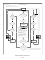
Operation sequence for
dehumidification
1. REMOVE 24 VOLTS FROM
DH AND/OR DS
2. THERMOSTAT CYCLES
OUTDOOR UNITS TO Y2
3. INDOOR AND OUTDOOR
FAN SPEEDS REDUCED
Trace cut for
Humiditrol (EDA)
application
Trace intact
ComfortSense 7000 or
7500 Thermostat
OUTDOOR UNITS (A175)
GREY
RED
EDA VALVE
ACTUATOR
EDA RELAY
BLACK
VIOLET
ORANGE
EDA VA LVE
ACTUATOR
EDA RELAY
RED
SEE TRACE CUT DETAIL.
SEE W1 JUMPER DETAIL.
Clip W1 Jumper for
Humiditrol (EDA)
application
LATER MODEL VALVE
ACTUATOR
EARLIER
MODEL VALVE
ACTUATOR
1N4005 DIODE (shrink wrapped -
diode is concealed in the wire.)
L1
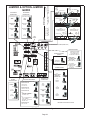
FIGURE 21. 24V Field Wiring (Non-Communicating Systems)

Page 20
Components
Unit Type
Thermostat
ComfortSense
®
7000 or 7500
Indoor iComfort
®
-enabled
Outdoor iComfort
®
-enabled
NUMBER OF WIRES REQUIRED—Indoor unit to: Air Sensors (Optional)
System Type Humiditrol
®
EDA
ComfortSense
®
7000 or 7500
Thermostats
Outdoor unit Outdoor Discharge
1-stage AC
3
8 4
2 2
2-stage AC 10 5
1-stage HP 8 6
2-stage HP 10 7
iComfort by Lennox
FURNACE (IFC) OR
AIR HANDLER (AHC)
Clip W1 Jumper for
Humiditrol (EDA)
application
Operation sequence for
dehumidification
1. REMOVE 24 VOLTS FROM DH AND/OR DS
2. THERMOSTAT CYCLES OUTDOOR UNITS TO
Y2
3. INDOOR AND OUTDOOR FAN SPEEDS
REDUCED
OUTDOOR
SENSOR
(X2658)
CHARGE
DOOR
Air Sensors
(optional)
Trace cut for
Humiditrol (EDA)
application
Trace intact
OUTDOOR UNITS (A175)
DS—R TRACE - MUST BE CUT FOR
HUMIDITROL OPERATION. SEE TRACE CUT
DETAIL
DS—R (W1) JUMPER - MUST BE CUT FOR
HUMIDITROL OPERATION. SEE W1 JUMPER
DETAIL.
ComfortSense 7000 or
7500
Thermostat
GREY
RED
EDA VALVE
ACTUATOR
EDA RELAY
1N4005 DIODE (shrink wrapped -
diode is concealed in the wire.)
BLACK
VIOLET
ORANGE
EDA VA LVE
ACTUATOR
EDA RELAY
RED
SEE TRACE CUT DETAIL.
SEE W1 JUMPER DETAIL.
LATER MODEL VALVE
ACTUATOR
EARLIER
MODEL VALVE
ACTUATOR
L1
FIGURE 22. Field Wiring (Non-Communicating Systems)
Page is loading ...
Page is loading ...
Page is loading ...
Page is loading ...
Page is loading ...
Page is loading ...
Page is loading ...
Page is loading ...
Page is loading ...
Page is loading ...
Page is loading ...
Page is loading ...
Page is loading ...
Page is loading ...
Page is loading ...
Page is loading ...
Page is loading ...
Page is loading ...
Page is loading ...
Page is loading ...
Page is loading ...
Page is loading ...
Page is loading ...
Page is loading ...
Page is loading ...
Page is loading ...
-
 1
1
-
 2
2
-
 3
3
-
 4
4
-
 5
5
-
 6
6
-
 7
7
-
 8
8
-
 9
9
-
 10
10
-
 11
11
-
 12
12
-
 13
13
-
 14
14
-
 15
15
-
 16
16
-
 17
17
-
 18
18
-
 19
19
-
 20
20
-
 21
21
-
 22
22
-
 23
23
-
 24
24
-
 25
25
-
 26
26
-
 27
27
-
 28
28
-
 29
29
-
 30
30
-
 31
31
-
 32
32
-
 33
33
-
 34
34
-
 35
35
-
 36
36
-
 37
37
-
 38
38
-
 39
39
-
 40
40
-
 41
41
-
 42
42
-
 43
43
-
 44
44
-
 45
45
-
 46
46


Lennox CBA38MV Air Handler User manual
- Category
- Split-system air conditioners
- Type
- User manual
- This manual is also suitable for
Ask a question and I''ll find the answer in the document
Finding information in a document is now easier with AI
Related papers
-
Lennox Variable Speed Air Handlers CBX32MV Installation Instructions Manual
-
-
-
-
-
-
Lennox EL18XCV Owner's manual
-
-
-
Other documents
-
Broan Downflow Adapter Kit for B5 B6 Installation guide
-
GE AUH4860ZGDA Installation guide
-
RectorSeal 97647 Installation guide
-
Allied Commercial 1.913029 Operating instructions
-
Mars HMG60E1P Operating instructions
-
Broan Downflow Adapter Kit for B5 B6 Installation guide
-
Allied BCE5C Installation guide
-
-
Broan H6HK Electric Heater Kit Product information
-
Allied 4HP15L60P Operating instructions