Supermicro SUPERO X8QB6-F User manual
- Category
- Server/workstation motherboards
- Type
- User manual
This manual is also suitable for

USER’S MANUAL
Revision 1.0a
X8QB6-F
X8QBE-F

Manual Revision 1.0a
Release Date: June 29, 2010
Unless you request and receive written permission from Super Micro Computer, Inc., you may not
copy any part of this document.
Information in this document is subject to change without notice. Other products and companies
referred to herein are trademarks or registered trademarks of their respective companies or mark
holders.
Copyright © 2010 by Super Micro Computer, Inc.
All rights reserved.
Printed in the United States of America
The information in this User’s Manual has been carefully reviewed and is believed to be accurate.
The vendor assumes no responsibility for any inaccuracies that may be contained in this document,
makes no commitment to update or to keep current the information in this manual, or to notify any
person or organization of the updates. Please Note: For the most up-to-date version of this
manual, please see our Website at www.supermicro.com.
Super Micro Computer, Inc. ("Supermicro") reserves the right to make changes to the product
described in this manual at any time and without notice. This product, including software and docu-
mentation, is the property of Supermicro and/or its licensors, and is supplied only under a license.
Any use or reproduction of this product is not allowed, except as expressly permitted by the terms
of said license.
IN NO EVENT WILL SUPER MICRO COMPUTER, INC. BE LIABLE FOR DIRECT, INDIRECT,
SPECIAL, INCIDENTAL, SPECULATIVE OR CONSEQUENTIAL DAMAGES ARISING FROM THE
USE OR INABILITY TO USE THIS PRODUCT OR DOCUMENTATION, EVEN IF ADVISED OF
THE POSSIBILITY OF SUCH DAMAGES. IN PARTICULAR, SUPER MICRO COMPUTER, INC.
SHALL NOT HAVE LIABILITY FOR ANY HARDWARE, SOFTWARE, OR DATA STORED OR USED
WITH THE PRODUCT, INCLUDING THE COSTS OF REPAIRING, REPLACING, INTEGRATING,
INSTALLING OR RECOVERING SUCH HARDWARE, SOFTWARE, OR DATA.
Any disputes arising between the manufacturer and the customer shall be governed by the laws of
Santa Clara County in the State of California, USA. The State of California, County of Santa Clara
shall be the exclusive venue for the resolution of any such disputes. Supermicro's total liability for
all claims will not exceed the price paid for the hardware product.
FCC Statement: This equipment has been tested and found to comply with the limits for a Class
A digital device pursuant to Part 15 of the FCC Rules. These limits are designed to provide
reasonable protection against harmful interference when the equipment is operated in a commercial
environment. This equipment generates, uses, and can radiate radio frequency energy and, if not
installed and used in accordance with the manufacturer’s instruction manual, may cause harmful
interference with radio communications. Operation of this equipment in a residential area is likely
to cause harmful interference, in which case you will be required to correct the interference at your
own expense.
California Best Management Practices Regulations for Perchlorate Materials: This Perchlorate
warning applies only to products containing CR (Manganese Dioxide) Lithium coin cells. “Perchlorate
Material-special handling may apply. See www.dtsc.ca.gov/hazardouswaste/perchlorate”.
WARNING: Handling of lead solder materials used in this
product may expose you to lead, a chemical known to
the State of California to cause birth defects and other
reproductive harm.

Preface
This manual is written for system integrators, PC technicians and
knowledgeable PC users. It provides information for the installation and use of the
X8QB6-F/X8QBE-F motherboard.
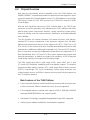
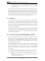
About This Motherboard
The X8QB6-F/X8QBE-F motherboard supports the Intel 7500 Series Socket-LS
processor, the fi rst generation chip multiprocessor (CMP) platform that offers Intel
QuickPath Interconnect (QPI) Technology, providing point-to-point system interface,
replacing the Front Side Bus. Integrating Intel Turbo Boost Technology, 45nm Pro-
cess Technology, combined with support of up to 32 CPU cores and 24MB L3 cache,
the X8QB6-F/X8QBE-F motherboard substantially enhances system performance
for HPC/Cluster/Database server platforms. Please refer to our Website (http://www.
supermicro.com) for updates on supported processors. This product is intended to
be installed and serviced by professional technicians.
Manual Organization
Chapter 1 provides quick installation instructions.
Chapter 2 describes the features, specifi cations and performance of the mother-
board and provides detailed information about the chipset.
Chapter 3 provides hardware installation instructions. Read this chapter when in-
stalling the processor, memory modules and other hardware components into the
system. If you encounter any problems, see Chapter 4, which describes trouble-
shooting procedures for video, memory and system setup stored in the CMOS.
Chapter 5 includes an introduction to the BIOS and provides detailed information
on running the CMOS Setup utility.
Appendix A provides BIOS Error Beep Codes.
Appendix B lists Other Software Program Installation Instructions.
Preface
iii

iv
Conventions Used in the Manual
Special attention should be given to the following symbols for proper installation and
to prevent damage done to the components or injury to yourself:
Danger/Caution: Instructions to be strictly followed to prevent catastrophic
system failure or to avoid bodily injury
Warning: Important information given to ensure proper system installation
or to prevent damage to the components
Note: Additional Information given to differentiate various models or pro-
vides information for correct system setup.
X8QB6-F/X8QBE-F Motherboard User’s Manual

Preface
v
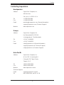
Contacting Supermicro
Headquarters
Address: Super Micro Computer, Inc.
980 Rock Ave.
San Jose, CA 95131 U.S.A.
Tel: +1 (408) 503-8000
Fax: +1 (408) 503-8008
Email: [email protected] (General Information)
[email protected] (Technical Support)
Website: www.supermicro.com
Europe
Address: Super Micro Computer B.V.
Het Sterrenbeeld 28, 5215 ML
's-Hertogenbosch, The Netherlands
Tel: +31 (0) 73-6400390
Fax: +31 (0) 73-6416525
Email: [email protected] (General Information)
[email protected] (Technical Support)
[email protected] (Customer Support)
Asia-Pacifi c
Address: Super Micro Computer, Inc.
4F, No. 232-1, Liancheng Rd.
Chung-Ho 235, Taipei County
Taiwan, R.O.C.
Tel: +886-(2) 8226-3990
Fax: +886-(2) 8226-3991
Website: www.supermicro.com.tw
Technical Support:
Email: [email protected]
Tel: 886-2-8228-1366, ext.132 or 139

vi
X8QB6-F/X8QBE-F Motherboard User’s Manual
Table of Contents
Preface
Chapter 1 Quick Installation Guide
1-1 Installing the CPU ...........................................................................................1-1
1-2 Installing the CPU/Heatsink/ CPU Fans ......................................................... 1-1
1-3 Installing the Memory Modules .......................................................................1-2
1-4 Installing the I/O Shield ...................................................................................1-2
1-5 Installing the Motherboard .............................................................................. 1-3
1-6 Connecting the Power Supply.........................................................................1-3
1-7 Installing Internal Peripherals .......................................................................... 1-4
1-8 Installing External Peripherals ........................................................................ 1-4
Chapter 2 Overview
2-1 Overview .........................................................................................................2-1
2-2 Chipset Overview ...........................................................................................2-11
2-3 Special Features ...........................................................................................2-12
2-4 PC Health Monitoring .................................................................................... 2-12
2-5 ACPI Features ...............................................................................................2-13
2-6 Power Supply ................................................................................................2-13
2-7 Super I/O .......................................................................................................2-14
2-8 Overview of the Nuvoton WPCM450R Controller ....................................... 2-14
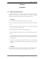
Chapter 3 Installation
3-1 Static-Sensitive Devices .................................................................................. 3-1
Precautions .....................................................................................................3-1
Unpacking .......................................................................................................3-1
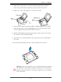
3-2 Processor and Heatsink Installation................................................................3-2
Installing an LGA 1567 Processor ..................................................................3-2
Installing a Passive CPU Heatsink ................................................................. 3-4
Removing the Passive Heatsink ..................................................................... 3-5
3-3 Installing and Removing the Memory Modules ...............................................3-6
Installing & Removing DIMMs .........................................................................3-6
Removing Memory Modules ........................................................................... 3-6
3-4 Motherboard Installation .................................................................................. 3-9
Tools Needed ..................................................................................................3-9
Location of Mounting Holes ............................................................................3-9
Installing the Motherboard ............................................................................ 3-10
3-5 Control Panel Connectors/I/O Ports...............................................................3-11
Back Panel Connectors/I/O Ports ..................................................................3-11
Back Panel I/O Port Locations and Defi nitions ............................................3-11

vii
Table of Contents
Universal Serial Bus (USB) ...................................................................... 3-12
Serial Port .................................................................................................3-13
Video Connection .....................................................................................3-13
Ethernet Ports ..........................................................................................3-14
Unit Identifi er Switch ................................................................................ 3-15
Front Control Panel .......................................................................................3-16
Front Control Panel Pin Defi nitions...............................................................3-17
NMI Button ...............................................................................................3-17
Power LED ..............................................................................................3-17
HDD LED ..................................................................................................3-18
NIC1/NIC2 LED Indicators .......................................................................3-18
Overheat (OH)/Fan Fail/PWR Fail/UID LED ............................................3-19
Power Fail LED ........................................................................................3-19
Reset Button ...........................................................................................3-20
Power Button ...........................................................................................3-20
3-6 Connecting Cables ........................................................................................ 3-21
Power Connectors ................................................................................... 3-21
Fan Headers .............................................................................................3-22
Chassis Intrusion .....................................................................................3-22
Internal Speaker .......................................................................................3-23
Power LED/Speaker ................................................................................. 3-23
TPM Header/Port 80 ................................................................................3-24
Overheat LED/Fan Fail ............................................................................ 3-24
Power SMB (I
2
C) Connector .................................................................... 3-25
IPMB .........................................................................................................3-25
T-SGPIO 1/2 Headers .............................................................................. 3-26
BBU Header (Optional for the X8QB6-F Only) ........................................3-26
3-7 Jumper Settings ............................................................................................3-27
Explanation of Jumpers ................................................................................ 3-27
GLAN Enable/Disable .............................................................................. 3-27
CMOS Clear .............................................................................................3-28
Watch Dog Enable/Disable ...................................................................... 3-28
VGA Enable .............................................................................................. 3-29
TPM Support Enable ................................................................................ 3-29
SAS2 Enable (X8QB6-F only) ..................................................................3-30
3-8 Onboard LED Indicators ............................................................................... 3-31
GLAN LEDs ..............................................................................................3-31
IPMI Dedicated LAN LEDs ....................................................................... 3-31
Onboard Power LED ............................................................................... 3-32

X8QB6-F/X8QBE-F Motherboard User’s Manual
viii
BMC Heartbeat LED ................................................................................ 3-32
Rear UID LED ......................................................................................... 3-33
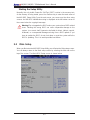
3-9 Serial ATA Connections .................................................................................3-34
Serial ATA Ports........................................................................................3-34
SAS2 Ports (X8QB6-F only).....................................................................3-34
Chapter 4 Troubleshooting
4-1 Troubleshooting Procedures ...........................................................................4-1
Before Power On ............................................................................................ 4-1
No Power ........................................................................................................4-1
No Video .........................................................................................................4-2
System Boot Failure .....................................................................................4-2
Losing the System’s Setup Confi guration .......................................................4-2
Memory Errors ...............................................................................................4-3
When the System Becomes Unstable ............................................................ 4-3
4-2 Technical Support Procedures ........................................................................ 4-4
4-3 Frequently Asked Questions ...........................................................................4-5
4-4 Returning Merchandise for Service.................................................................4-6
Chapter 5 BIOS
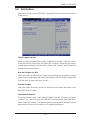
5-1 Introduction ......................................................................................................5-1
Starting BIOS Setup Utility .............................................................................. 5-1
How To Change the Confi guration Data ......................................................... 5-1
Starting the Setup Utility .................................................................................5-2
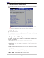
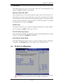
5-2 Main Setup ......................................................................................................5-2
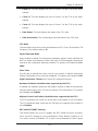
5-3 Advanced Setup Confi gurations......................................................................5-4
5-4 PCI/PnP Confi guration .................................................................................5-21
5-5 Boot Confi guration ........................................................................................5-23
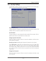
5-6 Security Settings ...........................................................................................5-25
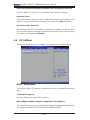
5-6 RC Settings ...................................................................................................5-26
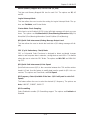
5-7 Chipset Settings ............................................................................................5-28
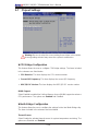
5-8 Exit Options ................................................................................................... 5-31
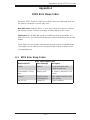
Appendix A BIOS Error Beep Codes
A-1 BIOS Error Beep Codes .................................................................................A-1
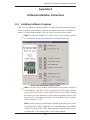
Appendix B Software Installation Instructions
B-1 Installing Software Programs ..........................................................................B-1
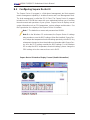
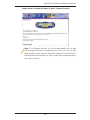
B-2 Confi guring Supero Doctor III .........................................................................B-2

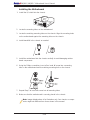
1-1
Chapter 1: Quick Installation Guide
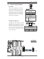
To avoid damage, do not rub the CPU pins against the socket.
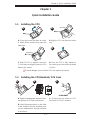
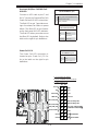
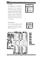
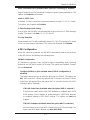
1-2 Installing the CPU/Heatsink/ CPU Fans
Chapter 1
Quick Installation Guide
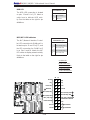
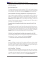
1-1 Installing the CPU
A B
C
D
A B
C
A. Press the socket clip down to unlock
it. Gently lift the socket clip to open the
load plate.
B. Align the CPU key with the socket
key.
D. Once the CPU is fully seated on
the socket, press the socket clip down
to lock it.
C. Align CPU Pin 1 against Socket Pin
1. Once they are aligned, lower the CPU
down to the socket.
A. Apply the appropriate amount of ther-
mal grease (to 0.13mm in thickness).
B. Insert the two push-pins on the sides
of the heatsink into the mounting holes
on the motherboard, turning clockwise
to lock them.
C. Connect the fan cables to CPU
Fan1 and CPU Fan 2 headers.
1
2
CPU Key
CPU Pin 1

1-2
X8QB6-F/X8QBE-F Motherboard User’s Manual
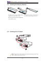
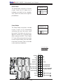
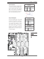
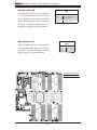
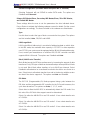
1-3 Installing the Memory Modules
1-4 Installing the I/O Shield
A B C
A
B
Note: Chassis and I/O plate images are for illustration purposes only. They
may be different from what you have.
A. Align the key on the DIMM module
against that of the DIMM socket.
B. Insert the DIMM module straight down
to the DIMM socket.
C. Press the notches on the ends of
the DIMM module inwards to lock it.

1-3
Chapter 1: Quick Installation Guide
X8QB6/X8QBE
Rev.1.01a
X8QB6/X8QBE
Rev.1.01a
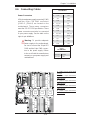
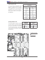
1-5 Installing the Motherboard
1-6 Connecting the Power Supply
A
B
C
D
A
B

1-4
X8QB6-F/X8QBE-F Motherboard User’s Manual
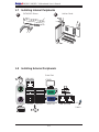
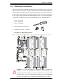
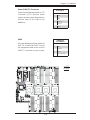
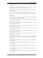
1-7 Installing Internal Peripherals
1-8 Installing External Peripherals
Add-on Cards
SATA/SAS2 Drives
A
B
IPMI LAN
Serial Port
(COM1)
Mouse
VGA Port LAN 1/2 PortsUSB 0/1
Keyboard
UID
Switch
USB 2/3

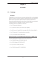
Chapter 2: Overview
2-1
Chapter 2
Overview
2-1 Overview
Checklist
Congratulations on purchasing your computer motherboard from an acknowledged
leader in the industry. Supermicro boards are designed with the utmost attention to
detail to provide you with the highest standards in quality and performance.
Please check that the following items have all been included with your motherboard.
If anything listed here is damaged or missing, contact your retailer.
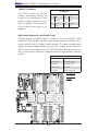
The following items are included in the retail box.
One (1) Supermicro Mainboard
•
Six (6) Serial ATA cables (CBL-0044Lx6) (for X8QBE-F)•
Two (2) I-Pass to 4 Serial ATA (50-cm) cables (CBL-097L-02) (for X8QB6-F)•
One (1) Supermicro CD containing drivers and utilities•
One (1) User's/BIOS Manual (MNL#1178)•
Optional (Required for Extended Battery Backup Support - X8QB6-F only)
The items listed below are available for purchase at Supermicro.
One (1) iBBU07 Battery (BTR-0018L-0000-LSI)
•
One (1) BBU Adaptor (BTR-0018L-ADPT)•
One (1) Extension Cable (CBL-0391L) •
One (1) BBU Bracket (MCP-240-00094-0N)•

2-2
X8QB6-F/X8QBE-F Motherboard User’s Manual
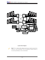
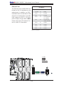
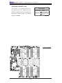
Motherboard Image
Note: All graphics shown in this manual were based upon the latest PCB
Revision available at the time of publishing of the manual. The motherboard
you've received may or may not look exactly the same as the graphics
shown in this manual.

Chapter 2: Overview
2-3
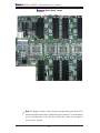
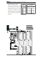
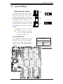
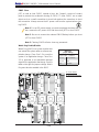
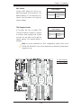
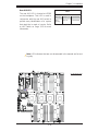
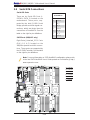
Motherboard Layout
Note: SAS2 connections and the LSI 2108 SAS2 Controller are available
on the X8QB6-F only. To enable battery backup support for onboard SAS,
an optional SAS Battery Backup Accessory kit is required. Refer to Page
3-26 in Chapter 3 for more details.
SAS_DBG1
LED26
JBT1
SP1
+
Battery
JWD1
JUID_OW1
JLPC1
LED12
LED35
LED18
LED16
LED15
LED23
LED20
LED17
LED14
LED19
LED21
LED24
VGA
COM1
JD1
JPRST1
LAN2
I-SATA5
I-SATA4
I-SATA3
I-SATA2
I-SATA1
JL1
PORT80
USB5
T-SGPIO1
BIOS
OHLED
Slot5 PCI-E 2.0 X8
Slot6 PCI-E 2.0 x16/X8
Slot2 PCI-E 2.0 x8
Slot3 PCI-E 2.0 x16/x8
FAN11
JF1
IPMB
FAN2
FAN1
FAN3
FAN4
FAN6
FAN7
FAN10
FAN8
FAN9
LAN1
USB0/1
IPMI_LAN
T-SGPIO2
JPW5
JPW3
JPW1
JPI2C
SAS4~7
SAS0~3
P3-DIMM1A
P3-DIMM8A
P3-DIMM7A
P3-DIMM6A
P3-DIMM5A
P3-DIMM4A
P3-DIMM3A
P3-DIMM2A
P4-DIMM5A
P4-DIMM6A
P4-DIMM7A
P4-DIMM8A
P4-DIMM1A
P4-DIMM2A
P4-DIMM3A
P4-DIMM4A
P2-DIMM6A
P2-DIMM5A
P2-DIMM8A
P2-DIMM7A
P2-DIMM1A
P2-DIMM2A
P2-DIMM3A
P2-DIMM4A
P1-DIMM8A
P1-DIMM7A
P1-DIMM6A
P1-DIMM5A
P1-DIMM4A
P1-DIMM3A
P1-DIMM2A
P1-DIMM1A
CPU1
CPU2
CPU3
UID_SWITCH
CPU4
UID_LED
BMC_HB
PVIOP12
I-SATA0
JPW4
JPW2
FAN5
X8QB6/X8QBE
Rev.1.01
BMC CTRL
LAN CTRL
Intel 82576
Intel ICH10R
Intel
IOH 7500
LSI 2108
SAS CTRL
Winbond
BIOS
Debug
D10
(Top)
BMC
Firmware
USB2/3
LED5
LED6
LED7
LED8
LED9
P5V_STBY
JPL1
BMCRST
BT2
JOH1
JPT1
JPS1
JPG1
JP3
JP1
(Bottom)
BBU
J59
D62
D61

2-4
X8QB6-F/X8QBE-F Motherboard User’s Manual
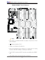
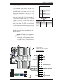
Notes:
See Chapter 3 for detailed information on jumpers, I/O ports and JF1 front
•
panel connections.
" " indicates the location of "Pin 1".
•
Jumpers not indicated are for testing only. •
When LED 8 (Onboard Power LED Indicator) is on, system power is on. Unplug •
the power cable before installing or removing any components.
The LSI SAS2 Controller and SAS2 Connections are available on the X8QB6-F
•
only.
LED Indicators that are not documented are for testing only.
•
X8QB6-F/X8QBE-F Quick Reference
SAS_DBG1
LED26
JBT1
SP1
+
Battery
JWD1
JUID_OW1
JLPC1
LED12
LED35
LED18
LED16
LED15
LED23
LED20
LED17
LED14
LED19
LED21
LED24
VGA
COM1
JD1
JPRST1
LAN2
I-SATA5
I-SATA4
I-SATA3
I-SATA2
I-SATA1
JL1
PORT80
USB5
T-SGPIO1
BIOS
OHLED
Slot5 PCI-E 2.0 X8
Slot6 PCI-E 2.0 x16/X8
Slot2 PCI-E 2.0 x8
Slot3 PCI-E 2.0 x16/x8
FAN11
JF1
IPMB
FAN2
FAN1
FAN3
FAN4
FAN6
FAN7
FAN10
FAN8
FAN9
LAN1
USB0/1
IPMI_LAN
T-SGPIO2
JPW5
JPW3
JPW1
JPI2C
SAS4~7
SAS0~3
P3-DIMM1A
P3-DIMM8A
P3-DIMM7A
P3-DIMM6A
P3-DIMM5A
P3-DIMM4A
P3-DIMM3A
P3-DIMM2A
P4-DIMM5A
P4-DIMM6A
P4-DIMM7A
P4-DIMM8A
P4-DIMM1A
P4-DIMM2A
P4-DIMM3A
P4-DIMM4A
P2-DIMM6A
P2-DIMM5A
P2-DIMM8A
P2-DIMM7A
P2-DIMM1A
P2-DIMM2A
P2-DIMM3A
P2-DIMM4A
P1-DIMM8A
P1-DIMM7A
P1-DIMM6A
P1-DIMM5A
P1-DIMM4A
P1-DIMM3A
P1-DIMM2A
P1-DIMM1A
CPU1
CPU2
CPU3
UID_SWITCH
CPU4
UID_LED
BMC_HB
PVIOP12
I-SATA0
JPW4
JPW2
FAN5
X8QB6/X8QBE
Rev.1.01
BMC CTRL
LAN CTRL
Intel 82576
Intel ICH10R
Intel
IOH 7500
LSI 2108
SAS CTRL
Winbond
BIOS
Debug
D10
(Top)
BMC
Firmware
USB2/3
LED5
LED6
LED7
LED8
LED9
P5V_STBY
JPL1
BMCRST
BT2
JOH1
JPT1
JPS1
JPG1
JP3
JP1
(Bottom)
BBU
J59
D62
D61

Chapter 2: Overview
2-5
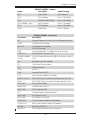
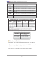
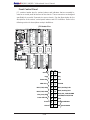
X8QB6-F/X8QBE-F Jumpers
Jumper
Description Default Setting
JBT1
Clear CMOS See Chapter 3
JPG1 VGA Enabled Pins 1-2 (Enabled)
JPL1 GLAN1/GLAN2 Enable Pins 1-2 (Enabled)
JPS1 (X8QB6-F only) SAS2 Enabled Pins 1-2 (Enabled)
JPT1 TPM Enabled Pins 1-2 (Enabled)
JWD1 Watch Dog Pins 1-2 (Reset)
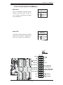
X8QB6-F/X8QBE-F Connectors
Connectors Description
BT2 Onboard Battery (See Chpt. 4 for Used Battery Disposal)
COM1 COM1 Serial Connection
FAN 1~10 CPU//System Fan Header
(Fan 11: Reserved)
IPMB 4-pin External BMC I
2
C Header (for an IPMI Card)
I-SATA 0~5 Intel SB SATA Connectors 0~5
J59 (BBU) (X8QB6-
F only)
LSI SAS Battery Backup Unit (BBU) (See Note on Pg.2-6,
3-26)
JD1 Speaker/Power LED Indicator
JF1 Front Panel Control Header
JL1 Chassis Intrusion
JLPC1 Port 80
JOH1 Overheat/Fan Fail LED
JPI
2
C Power Supply SMBbus I
2
C Header
JPW1~2, JP4~5 12V 8-Pin Power Connectors (See Warning on Pg. 2-6.)
JPW3 ATX 24-Pin Power Connector (See Warning on Pg. 2-6.)
JUID_OW1 UID Override Header
LAN1/LAN2 G-bit Ethernet Ports 1/2
(IPMI) LAN IPMI_Dedicated LAN
SP1 Onboard Buzzer (Internal Speaker)
Slot2, Slot5 PCI-Express 2.0 x8
Slot3, Slot6 PCI-Express 2.0 x16/x8
TPM/Port 80 Trusted Platform Module/Port 80 Header
T-SGPIO 1/2 Serial_Link General Purpose I/O Headers
USB 0/1 Back Panel USB 0/1
USB 2/3, 5 Front Panel Accessible USB Connections

2-6
X8QB6-F/X8QBE-F Motherboard User’s Manual
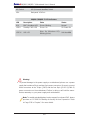
Warning!
To prevent damage to the power supply or motherboard, please use a power
•
supply that contains a 24-pin and two 8-pin power connectors. Be sure to connect
these connectors to the 24-pin (JPW3) and the four 8-pin (JPW1~2,JPW4~5)
power connectors on the motherboard. Failure in doing so will void the manu-
facturer warranty on your power supply and motherboard.
Note: To enable extended battery backup support for onboard SAS, please
purchase a LSI 2108 SAS Battery Accessory kit from Supermicro. Refer
to Page 3-26 in Chapter 3 for more details.
UID Switch UID (Universal Identifi er) Switch
VGA Backpanel VGA Port
X8QB6-F/X8QBE-F LED Indicators
LED Description State Status
D10 BMC Heartbeat LED Green: Blinking Normal
LED 8 Standby PWR LED Green: On SB Power On
LED 26 UID LED
Blue: On (Windows OS),
Blinking (Linux)
Unit Identifi ed

Chapter 2: Overview
2-7
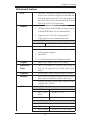
Motherboard Features
CPU
Four Intel•
®
7500 Series (Socket LS-LGA 1567) pro-
cessors; each processor supports four full-width Intel
QuickPath Interconnect (QPI) links (with support of
up to 25.6 GT/s per QPI link and with Data Transfer
Rate of up to 6.4 GT/s per direction)
Memory
Integrated memory controller supports:•
32 240-pin DDR3-1066 RDIMMs running at speeds 1.
of 1066/978/800 MHz (via an onboard buffer)
Support for up to 256 GB of Registered ECC 2.
DDR3 memory in two-channel memory bus
DIMM sizes
RDIMM
• 1 GB, 2GB, 4GB, and 8GB
Virtualization: VT-x, VT-d, and VT-c
•
I/O: Intel® QuickData Technology with Intel 82576 •
LAN Controller, supports:
Intel 825761.
LSI 2108 (Hardware RAID w/Battery Backup)2.
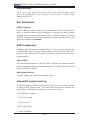
Chipset
Intel® 7500 Chipset (7500 IOH & ICH10R)•
Expansion
Two (2) PCI Express 2.0 x16 slots (Slot3, Slot6), or•
Four (4) PCI Express2.0 x8 (Slot2, Slot5, Slot3, •
Slot6)
Slots
Graphics
Winbond BMC Video Controller (Matrox G200eW)•
Network
One Intel 82576 Gigabit (10/100/1000 Mb/s) Ethernet •
Dual-Channel Controller for LAN 1/LAN 2 ports.
Winbond WP450R Base-board Controller (BMC)
•
supports IPMI_LAN 2.0
I/O Devices
SATA Connections
SATA Ports
• Six (6)
RAID (Win-
•
dows)
RAID 0, 1, 5, 10
RAID (Linux)
• RAID 0, 1, 10
SAS2 Connections
LSI SAS2 2108 Controller
•
SAS2 Ports• 0~3, 4~7
RAID Support
• RAID 0, 1, 5, 6, 10, 50, 60

2-8
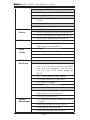
X8QB6-F/X8QBE-F Motherboard User’s Manual
Integrated IPMI 2.0
IPMI 2.0 supported by the WPCM450R BMC
•
Serial (COM) Port
One (1) Fast UART 16550 Connection: 9-pin RS-
•
232 port
Super I/O
Winbond Super I/O 83527
•
Peripheral
Devices
USB Devices
Two (2) USB ports on the rear I/O panel (USB 0/1)
•
One (1) USB connection for front access (USB 5)•
One (1) Type A internal connector (USB 2/3)•
BIOS
64 Mb SPI AMI BIOS•
®
SM Flash BIOS
APM 1.2, PCI 2.3, ACPI 1.0/2.0/3.0, USB Keyboard,
•
Plug & Play (PnP) and SMBIOS 2.5
Power
ACPI/ACPM Power Management•
Confi g.
Main switch override mechanism•
Keyboard Wake-up from Soft-Off•
Power-on mode for AC power recovery•
PC Health
CPU Monitoring
Monitoring
Onboard voltage monitors for CPU1 Vcore, CPU2 •
Vcore, CPU3 Vcore, CPU4 Vcore, NIC Vcore, BMC
Vcore, AUX Vcore, Standby ME Vcore, 12V Scale,
1.5V, 3.3V Vcc(V), 3.3VSB, Battery Voltage, and
IOPV12.
CPU 7-Phase switching voltage regulator
•
CPU/System overheat LED and control•
CPU Thermal Trip support•
Thermal Monitor 2 (TM2) support•
Fan Control
Fan status monitoring with fi rmware 4-pin (Pulse
•
Width Modulation) fan speed control
Low noise fan speed control
•
System
Management
PECI (Platform Environment Confi guration Interface) •
2.0 support
System resource alert via Supero Doctor III
•
SuperoDoctor III, Watch Dog, NMI•
Chassis Intrusion Header and Detection•
Page is loading ...
Page is loading ...
Page is loading ...
Page is loading ...
Page is loading ...
Page is loading ...
Page is loading ...
Page is loading ...
Page is loading ...
Page is loading ...
Page is loading ...
Page is loading ...
Page is loading ...
Page is loading ...
Page is loading ...
Page is loading ...
Page is loading ...
Page is loading ...
Page is loading ...
Page is loading ...
Page is loading ...
Page is loading ...
Page is loading ...
Page is loading ...
Page is loading ...
Page is loading ...
Page is loading ...
Page is loading ...
Page is loading ...
Page is loading ...
Page is loading ...
Page is loading ...
Page is loading ...
Page is loading ...
Page is loading ...
Page is loading ...
Page is loading ...
Page is loading ...
Page is loading ...
Page is loading ...
Page is loading ...
Page is loading ...
Page is loading ...
Page is loading ...
Page is loading ...
Page is loading ...
Page is loading ...
Page is loading ...
Page is loading ...
Page is loading ...
Page is loading ...
Page is loading ...
Page is loading ...
Page is loading ...
Page is loading ...
Page is loading ...
Page is loading ...
Page is loading ...
Page is loading ...
Page is loading ...
Page is loading ...
Page is loading ...
Page is loading ...
Page is loading ...
Page is loading ...
Page is loading ...
Page is loading ...
Page is loading ...
Page is loading ...
Page is loading ...
Page is loading ...
Page is loading ...
Page is loading ...
Page is loading ...
Page is loading ...
Page is loading ...
Page is loading ...
Page is loading ...
Page is loading ...
Page is loading ...
Page is loading ...
Page is loading ...
Page is loading ...
Page is loading ...
Page is loading ...
-
 1
1
-
 2
2
-
 3
3
-
 4
4
-
 5
5
-
 6
6
-
 7
7
-
 8
8
-
 9
9
-
 10
10
-
 11
11
-
 12
12
-
 13
13
-
 14
14
-
 15
15
-
 16
16
-
 17
17
-
 18
18
-
 19
19
-
 20
20
-
 21
21
-
 22
22
-
 23
23
-
 24
24
-
 25
25
-
 26
26
-
 27
27
-
 28
28
-
 29
29
-
 30
30
-
 31
31
-
 32
32
-
 33
33
-
 34
34
-
 35
35
-
 36
36
-
 37
37
-
 38
38
-
 39
39
-
 40
40
-
 41
41
-
 42
42
-
 43
43
-
 44
44
-
 45
45
-
 46
46
-
 47
47
-
 48
48
-
 49
49
-
 50
50
-
 51
51
-
 52
52
-
 53
53
-
 54
54
-
 55
55
-
 56
56
-
 57
57
-
 58
58
-
 59
59
-
 60
60
-
 61
61
-
 62
62
-
 63
63
-
 64
64
-
 65
65
-
 66
66
-
 67
67
-
 68
68
-
 69
69
-
 70
70
-
 71
71
-
 72
72
-
 73
73
-
 74
74
-
 75
75
-
 76
76
-
 77
77
-
 78
78
-
 79
79
-
 80
80
-
 81
81
-
 82
82
-
 83
83
-
 84
84
-
 85
85
-
 86
86
-
 87
87
-
 88
88
-
 89
89
-
 90
90
-
 91
91
-
 92
92
-
 93
93
-
 94
94
-
 95
95
-
 96
96
-
 97
97
-
 98
98
-
 99
99
-
 100
100
-
 101
101
-
 102
102
-
 103
103
-
 104
104
-
 105
105


Supermicro SUPERO X8QB6-F User manual
- Category
- Server/workstation motherboards
- Type
- User manual
- This manual is also suitable for
Ask a question and I''ll find the answer in the document
Finding information in a document is now easier with AI
Related papers
-
Supermicro X8QB6-F User manual
-
Supermicro X9DRE-TF+ User manual
-
-
-
-
-
-
-
-
Supermicro MBD-X9SCV-Q-B User manual
Other documents
-
 Supero X9DRFR User manual
-
 RadiSys PROCELERANT SB5520DT1-SAS User manual
-
Zebra NX-7510/NX-7520/NX-7530 Owner's manual
-
Dell PowerEdge R810 User guide
-
-
Intel ICH10R User manual
-
 Acoustic Energy Aego BT2 User manual
-
Dell PowerEdge C6105 Hardware Owner's Manual
-
Gigabyte GA-7TCSV2 User manual
-
Renkforce 0+10 ports SATA III controller card PCIe Owner's manual


