Falcon G2102 Installation And Servicing Instructions

Category
Ovens
Type
Installation And Servicing Instructions

This manual is also suitable for

G2102 FORCED
CONVECTION OVEN RANGE
G2112 FORCED
CONVECTION OVEN (May 2010)
INSTALLATION and SERVICING INSTRUCTIONS
These appliances must be installed and serviced by a competent person as stipulated by the Gas Safety
(Installation & Use) Regulations.
IMPORTANT
The installer must ensure that the installation of the appliance is in conformity with these instructions and National
Regulations in force at the time of installation. Particular attention MUST be paid to –
BS7671 I.E.E. Wiring Regulations Electricity At Work Regulations
Gas Safety (Installation & Use) Regulations Health And Safety At Work etc. Act
Local and National Building Regulations Fire Precautions Act
Detailed recommendations are contained in Institute of Gas Engineers published documents :
IGE/ UP/ 1, IGE/ UP/ 2
BS6173 and BS5440
The appliances have been CE-marked on the basis of compliance with the Gas Appliance Directive, EMC and Low
Voltage Directive for the Countries, Gas Types, Gas Pressures and voltages as stated on the Data Plate.
WARNING - TO PREVENT SHOCKS, ALL APPLIANCE MUST BE EARTHED
On completion of the installation, these instructions should be left with the Engineer-in-Charge for reference during
servicing. Further to this, The Users Instructions should be handed over to the User, having had a demonstration of
the operation and cleaning of the appliance.
IT IS MOST IMPORTANT THAT THESE INSTRUCTIONS BE CONSULTED BEFORE INSTALLING AND COMMISSIONING
THIS APPLIANCE. FAILURE TO COMPLY WITH THE SPECIFIED PROCEDURES MAY RESULT IN DAMAGE OR THE NEED
FOR A SERVICE CALL.
PREVENTATIVE MAINTENANCE CONTRACT
In order to obtain maximum performance from this unit we would recommend that a Maintenance Contract be
arranged with SERVICELINE. Visits may then be made at agreed intervals to carry out adjustments and repairs. A
quotation will be given upon request to the contact numbers below.
WEEE Directive Registration No. WEE/DC0059TT/PRO
At end of unit life, dispose of appliance and any replacement parts in a safe manner, via a
licensed waste handler.
Units are designed to be dismantled easily and recycling of all material is encouraged
whenever practicable.
Falcon Foodservice Equipment
Head Office and Works
Wallace View, Hillfoots Road, Stirling. FK9 5PY. Scotland.
Serviceline
PHONE : 01438 363 000
T100732 Ref.5
Warranty Policy Shortlist
Warranty does not cover :-
Correcting faults caused by incorrect installation of a product.
Where an engineer cannot gain access to a site or a product.
Repeat commission visits.
Replacement of any parts where damage has been caused by misuse.
Engineer waiting time will be chargeable.
Routine maintenance and cleaning.
Gas conversions i.e. Natural to Propane gas.
Descaling of water products and cleaning of water sensors where softeners/conditioners are not fitted, or are fitted
and not maintained.
Blocked drains.
Independent steam generation systems.
Gas, water and electrical supply external to unit.
Light bulbs.
Re-installing vacuum in kettle jackets.
Replacement of grill burner ceramics when damage has been clearly caused by misuse.
Where an engineer finds no fault with a product that has been reported faulty.
Re-setting or adjustment of thermostats when unit is operating to specification.
Cleaning and unblocking of fryer filter systems due to customer misuse.
Lubrication and adjustment of door catches.
Cleaning and Maintenance
Cleaning of burner jets
Poor combustion caused by lack of cleaning
Lubrication of moving parts
Lubrication of gas cocks
Cleaning/adjustment of pilots
Correction of gas pressure to appliance.
Renewing of electric cable ends.
Replacement of fuses
Corrosion caused by use of chemical cleaners.
SECTION 1 – INSTALLATION
UNLESS OTHERWISE STATED, PARTS WHICH HAVE BEEN PROTECTED BY THE MANUFACTURER ARE NOT TO BE
ADJUSTED BY THE INSTALLER
1.1 MODEL NUMBERS, NETT WEIGHTS and DIMENSIONS
MODEL
WIDTH
mm
DEPTH
mm
HEIGHT
mm
WEIGHT
kg
G2102 RANGE
900
855
870
221
G2112 OVEN
ON STAND
900
855
13
10
190
G2112/2
DOUBLE TIER
900
855
1465
362
G2112 OVEN
ON LEGS
900
855
870
181
1.2 SITING
All units, other than G2112 oven on stand or legs, must be installed on a non-combustible floor. All units must be
situated on a level surface. Although the appliance feet are adjustable to facilitate levelling, the adjustment range is
limited.
A clearance of at least 150mm must be allowed from any combustible wall.
If practicable, it is recommended that a space of at least 400mm be allowed from any side wall to provide clearance
for adjusting the rear levelling bolts, and to effect the removal of the RH side panel to facilitate servicing.
A vertical clearance of 1200mm minimum must be allowed between the top edge of flue outlet and any overlying
combustible surface.
If unit is being installed as part of a suite, it is also recommended that it be positioned at the RH end to provide
unrestricted access for servicing the controls, etc. Furthermore, if installed in a suite, either central or adjacent to a
wall, with a boxed-in void at the rear, it is vitally important that the void be adequately ventilated to ensure a supply
of air to the motor cooling fan at the rear of the oven.
Important
Care must be taken not to disturb the air combustion admission and evacuation of appliances fitted with open
burners.
1.3 VENTILATION
Recommendations for Ventilation of Catering Appliances are given in BS5440 : 2. Furthermore, to ensure
sufficient room ventilation, guidance on the volume of ventilation air required for different types of catering
equipment is provided in the table above. For multiple installations the requirements for individual appliances
should be added together. Installation should be made in accordance with local and/ or national regulations applying
at the time. A competent installer MUST be employed.
The oven flue discharges vertically through the grille at the hob rear.
EQUIPMENT
VENTILATION RATE REQUIRED
m³/min
ft³/min
Range, unit type
17
600
Pastry Oven
17
600
Fryer
26
900
Grill
17
600
Steak Grill
26
900
Boiling Pan
17
600
Steamer
17
600
Sterilizing Sink
14
500
Bains Marie
11
400
Tea/Coffee Machine
8.5
-
14
300
-
500
There must be no direct connection of the flue to any mechanical extraction system or the outside air. Open top
burners discharge combustion products directly into the room. Siting the appliance under a canopy is the ideal
arrangement.
1.4 GAS SUPPLY
The incoming service must be of sufficient size to supply full rate without excessive pressure drop. A gas meter is
connected to the service pipe by the Gas Supplier. Any existing meter should be checked by the Gas Supplier to
ensure the meter is of adequate capacity to pass the required rate of gas.
Installation pipe work should be fitted in accordance with IGE/UP/2. The pipe should be of adequate size but not
smaller than the gas inlet. Connections are as follows:
G2102 Range:
Rp3/4
(3/4" BSP female)
G2112 Oven:
Rp1/2 (1/2"BSP female)
An isolating cock must be located close to the appliance to allow shut-down during an emergency or servicing. The
installation must be tested for gas soundness and purged as specified in IGE/UP/1.
Note
The G2102 open top range is supplied complete with the necessary pipework for linking oven and open top burner
sections. The governor necessary for open top burners is incorporated in this pipework for Natural Gas operation,
and an extra governor must not be fitted to any of these appliances.
1.5 ELECTRICAL SUPPLY
The oven is equipped with a length of 3-core flexible cord for connecting to an electrical supply. A standard 13 amp
socket outlet can be used, in which case the plug must be fitted with a 3 amp fuse. If the supply is through a
distribution fuse box, it must be via a fuse having a maximum rating of 5 amp.
1.6 WATER SUPPLY
Not applicable to these appliances.
1.7 TOTAL GAS RATES -
Natural and Propane Gas
Model
kw
(net)
Btu/hr (gross)
G2102
50.8
190,700
G2112
19
71,300
G2112/2
38
142,600
1.7.1 Individual Burner Ratings -
Natural and Propane Gas
Burner type
kw (net)
Bty/hr (gross)
Open top (x6)
5.3
20,000
oven
19
71,300
1.8 INJECTOR DIAMETERS - Natural & Propane Gas
Natural Gas
Propane Gas
Open top
Ø1.92mm
Ø1.2mm
Oven
Ø3.4mm
Ø2.2mm
Oven Pilot
G29.2
G24.1
1.9 GAS PRESSURE
Supply Pressure
Burner Operating Pressure
Oven Ignition pressure
Nat
Prop
Nat
Prop
Nat
Prop
mbar
20
37
15
37
5
12
1.10 BURNER ADJUSTMENTS
1.10.1 Burner Aeration
All burners have fixed aeration, and no modifications to the size of air-entry should be attempted.
1.10.2 Open Top - Bypass Screw Details
The minimum flow to burner is governed by the size of the fixed hole in bypass screw as detailed below:-
Natural
Gas
No.76
Propane Gas
No.51
1.11 FAN UNIT
This fan has two impellors, directly mounted on the motor shaft. The main impellor is inside the oven, its purpose
being to circulate air across the heat-exchangers and around the cooking space, while a smaller, externally mounted
impellor serves to cool the motor and control compartment.
SECTION 2 - ASSEMBLY and COMMISSIONING
2. 1 ASSEMBLY
2.1.1 G2102 Open Top Range
a) Unpack unit, open oven doors and remove inter-connecting pipework (and governor on natural gas appliances)
from inside.
b) Fit interconnecting pipework, leaving incoming pipe entry facing in desired direction to suit service pipe.
c) Place unit into desired location, if necessary adjust levelling bolts. Access to these, at front, is gained upon
removing burner grille below oven doors. The rear bolts are accessible via openings in outer back panel. Do not raise
unit more than is absolutely necessary to effect levelling.
d) Connect to gas supply and test for gas soundness, using soap solution or leak detection fluid.
e) Connect to electrical supply ensuring flexible cord does not make contact with flue or other hot areas.
The wires of flexible cord must be connected to supply as follows:
Brown to Live
Blue to Neutral
Green/Yellow to Earth
This appliance MUST be earthed.
2.1.2 G2112 Oven on Legs
Installation procedure is as Section 2.1.1, but omit (b) and for (c) it is not necessary to remove lower front panel.
Levelling is now effected by turning lower parts of the feet.
2.1.3 G2112 Oven on Stand
Installation procedure is as follows:
a) Unpack oven and stand that is packed separately in a dismantled state.
b) Assemble stand (see Figure 1) using this procedure:
1. Position bottom shelf (A) over frame (B) and secure stand legs (C) to frame (B) using M8 fixings to secure from
below.
2. Fit adjustable legs (D) and stiffening plates (E) to frame (B) using M6 fixings provided.
3. Using pliers or a similar tool, bend and remove tabs from front brackets.
4. Lift oven carefully upon stand and ensure mounting brackets are secured to oven base, lined up with the leg top
brackets. Secure oven to stand using M6 fixings through holes indicated in Figure 1.
5. Manoeuvre oven and stand into desired location and level by turning lower part of the feet.
6. Connect to gas and electrical supplies as detailed in Sections 1.4 and 1.5.
FIGURE 1.
2.1.4. G2112/2 Two Tier Oven (See Figure 2)
These units are marked as TOP and BOTTOM ovens before leaving the factory. The top unit is identified by having a
worktop on top.
Proceed as follows:
a) Place lower oven in approximate final location.
b) Remove bottom grille on upper oven. To effect removal, slacken grille fixings beneath oven doors. Remove control
panel and grille base fixings.
c) Lift top unit onto lower unit, taking care not to damage upturned flange at rear of lower unit. Align back edge of
top unit carefully against back flange.
d) Secure top unit to lower unit using M6 x 50mm fixings provided. (Two at base front corners and two at rear
through rectangular openings in lower corners of outer back panel).
e) Fit pipework supplied for interconnecting the two individual gas inlets.
f) Manoeuvre double unit into final position and carefully level by adjusting levelling bolts in bottom oven base. Do
not adjust more than is necessary to effect a true level.
g) Connect to gas and electrical supplies as detailed in Sections 1.4 and 1.5.
Figure 2.
2.1.5 Assembly of Splashplate and Plate Shelf (See Figure 3)
a) Fix as per instructions supplied with kit.
2.2 CONNECTION TO A GAS SUPPLY
The gas supply piping and connection to unit must be installed in accordance with the various regulations listed on
front page of this document. Refer further to Section 1.4 and check gas soundness.
2.3 CONNECTION TO AN ELECTRICAL SUPPLY
The electrical connections must comply with relevant standards listed on the front page of this document. Refer
further to Section 1.5.
2.4 CONNECTION TO A WATER SUPPLY
Not applicable to these appliances.
2.5 PRE-COMMISSIONING CHECK
Ensure lift-off hob with open-top burners (where applicable) or worktop and oven linings are properly located. Check
also that oven grid shelves slide in and out easily. Check all packing material has been removed. It is necessary for
gas pressure to be checked before the unit is commissioned. A suitable pressure gauge must be connected to
pressure test point(s) as follows:
2.5.1 Open Top Burners (where applicable).
Pull gas tap knobs off and remove control panel to access test point. Refer to Section 1.9 for pressure settings. Three
burners should be operating on full flame when setting burner operating pressure.
The open top burner gas pressure is adjusted by means of external governor mounted at rear of unit.
2.5.2 Ovens
FIRST ENSURE ELECTRICITY SUPPLY IS OFF.
Remove oven control panel as detailed in Section 3.2.1 and draw panel forward on its slides. Remove burner grille (4
screws).
Connect pressure gauge to outlet test point immediately below multifunctional gas control.
Note that inlet and outlet points are provided on control also.
a) Light oven as described in accompanying User's Instructions. At this stage, take care not to touch live connections
which are now exposed behind withdrawn oven control panel.
b) Oven burner is controlled by a two stage multifunctional control. Pressure should pause for a brief period at an
intermediate level (oven ignition pressure) before attaining burner operating pressure. Refer to Section 1.9 for
these settings. If adjustment is necessary, refer to Sections 2.5.4 to 2.5.6
c) Switch off appliance by pressing OFF button on gas control valve and turn off electricity supply at mains. Replace
test point screws, control panels etc.
2.5.3 Checking Performance Of The Controls
When satisfied that pressures are set correctly in accordance with Sections 2.5.1 and 2.5.2. Proceed as follows:
Oven
a) Light oven as detailed in User Instructions. Set thermostat at 250°C and allow oven to heat up, ensuring fan is
operating and turning anti-clockwise when viewed from front.
b) Turn thermostat down to lowest setting and check oven burner goes out leaving pilot burner lit.
c) Turn thermostat knob to a high setting whereupon oven burner should re-light smoothly with little or no delay.
d) Check fan stops and that oven burner goes out when oven doors are opened.
e) Check operation of power switch. When OFF fan should stop and main burner is extinguished. Pilot burner,
however, remains lit.
f) Timer check. This does not turn off gas to oven but simply provides user with an audible signal that pre-set time
has elapsed.
g) Press oven light button, check light is operates.
Open Top
Light open top as detailed in User Instructions. Check ignition is smooth and without delay. Repeat this operation
several times.
2.5.4 Multifunctional Control Description
Access to control is gained upon withdrawal of control panel. Refer to Section 3.2.1.
This is a two stage multifunctional control which contains a number of features for effecting adjustments. Refer
to Figure 3.
When supplied fitted in unit, this component is factory set and should not require adjustment.
The following adjusters are available:
a) Two test points are provided for measuring inlet and outlet pressures as detailed in Figure 3. For convenience, a
further outlet pressure test point is provided in outlet immediately below control valve.
b) Pressure adjusting screw (REG.ADJ)
c) Pilot adjusting screw (PILOT ADJ). This screw is provided on control for adjusting flow of gas to pilot burner. The
unit is designed to operate on full gas flow to pilot. To ensure full flow is available, turn screw fully clockwise then
back 2 complete turns.
d) A screw marked NO PR. This is for rendering inbuilt governor (i.e. pressure regulator) inoperative and is
turned when propane is used.
Note
On no account must the NO PR screw be in an intermediate position, i.e. it must be fully clockwise for natural gas, or
fully anti-clockwise for Propane.
e) A screw marked 1 STEP ADJ. This is a device enabling gas supply to burner to flow at reduced rate initially,
automatically increasing to full rate after a brief time interval. This assists in effecting smooth ignition of the gas. The
oven ignition pressure is detailed in Section 1.9.
Should adjustment be necessary, refer to appropriate Sections 2.5.5 or 2.5.6.
Note
The gas control valve is fitted with a safety interlock. Therefore, a period of 3 minutes will elapse before it is
possible to re-light after complete shut-down.
Thermocouple connection Pilot connection
(behind) (behind)
Inlet pressure
test point
Main burner button
Pilot adjustment
1
st
step adjustment
Off button
Reg Adjustment
Pilot button Outlet pressure
Test point
No Pr
Figure 3.
2.5.5 MFC Set-Up Procedure (Natural Gas)
1. Remove screw from outlet test point and connect gauge.
2. Ensure mains supply to unit is switched off.
3. Remove protective caps from screws marked NO PR, 1 STEP ADJ and REG ADJ.
4. Ensure NO PR screw is turned fully clockwise.
5. Ensure 1 STEP ADJ screw is turned fully clockwise.
6. Switch I/O fan switch and thermostat OFF ('O').
7. Press and hold pilot button in fully while repeatedly pressing and releasing igniter button until pilot lights.
8. Continue to hold pilot button in fully for 20 seconds before release. Pilot should remain alight but if it goes out,
push OFF button in and wait for the 3 minute lockout to release before repeating from Step 7.
9. Push main burner button down.
10. Switch main electrical supply to unit on and check that red neon becomes lit.
11. Switch I/O fan switch on. Set thermostat to 200C.
12. Adjust REG ADJ screw to achieve gas pressure of 15mbar (6" w.g.). Clockwise rotation to increase pressure and
vice versa.
13. Turn 1 STEP ADJ screw anti-clockwise, no more than a quarter turn. If necessary, re-adjust REG ADJ screw to
restore gas pressure to 15mbar.
14. Extinguish burner by turning thermostat knob OFF.
15. Re-light burner by turning thermostat knob to FULL while observing pressure gauge. Pressure should initially be 5
mbar, pausing for a brief period at this pressure before rising to full pressure of 15 mbar.
16. If, when performing operation in Step 15, initial pressure does not register or is below 5 mbar, open 1 STEP ADJ
screw a further eighth-turn and if necessary re-adjust REG ADJ screw to restore gas pressure to 15 mbar. Repeat
from Step 14.
When satisfied that burner pressure is correct and the two-stage ignition pressure facility produces smooth burner
lighting, turn off main gas and electrical supplies. Remove pressure gauge, replace pressure test point screw and
replace protective caps.
2.5.6 MFC Set-Up Procedure (Propane Gas)
1. Remove screw from outlet pressure test point and connect gauge.
2. Ensure mains supply to unit is switched off.
3. Remove protective caps from screws marked NO PR and 1 STEP ADJ.
4. Ensure NO PR screw is turned fully anti-clockwise.
5. Ensure 1 STEP ADJ screw is turned fully clockwise.
6. Switch I/O fan switch and thermostat to OFF ('O').
7. Press and hold pilot button in fully while repeatedly pressing and releasing igniter button until pilot lights.
8. Continue to hold pilot button in fully for 20 seconds before release. The pilot should remain alight. If it goes out,
push OFF button in and wait for the 3 minute lockout to release before repeating from Step 7.
9. Push main burner button down.
10. Switch main electrical supply to unit on and check that red neon becomes lit.
11. Switch I/O fan switch on, set thermostat to 200Žo
C.
12. Turn 1 STEP ADJ screw anti-clockwise by no more than an quarter turn.
13. Extinguish burner by turning thermostat knob to OFF.
14. Re-light burner by turning thermostat knob to FULL while observing pressure gauge. Pressure should initially be
12 mbar, pausing for a brief period at this pressure before rising to full pressure of 37 mbar (14.8" w.g.).
15. If when performing operation in Step 14, initial pressure does not register or is below 12 mbar, open 1 STEP ADJ
screw a further eighth-turn and turn burner OFF by turning thermostat knob OFF and repeat from Step 14.
When satisfied that burner pressure is correct and the two-stage ignition pressure facility produces smooth burner
lighting, turn off main gas and electrical supplies. Remove pressure gauge, replace pressure test point screw and
replace protective caps.
2.6 INSTRUCTION TO USER
Important
After installing and commissioning appliance, hand User Instructions to user or purchaser and ensure the
instructions for lighting, turning off, correct use and cleaning are properly understood. The location of gas isolating
cock and electrical supply switch should be made known to user and the procedure for that operation in an
emergency demonstrated.
SECTION 3 - SERVICING and CONVERSION
Important
BEFORE ATTEMPTING ANY SERVICING ENSURE THAT THE ISOLATING COCK AND MAIN ELECTRICAL SUPPLY ARE
TURNED OFF AND THAT IT CANNOT BE INADVERTENTLY TURNED BACK ON.
Note
WHEN REPLACING CONNECTIONS, REFER TO WIRING DIAGRAM IN THIS MANUAL. ALL WIRES ARE NUMBERED.
AFTER ANY MAINTENANCE TASK, CHECK THE APPLIANCE TO ENSURE THAT IT PERFORMS CORRECTLY AND CARRY
OUT ANY NECESSARY ADJUSTMENTS AS DETAILED IN SECTION 1.
After carrying out any servicing or exchange of gas carrying components -
ALWAYS CHECK FOR GAS SOUNDNESS!
3.1 GAS CONVERSION CHECK LIST
For conversion to NATURAL GAS, add correct external governor for G2102 hob and set the burner pressure on OT
manifold. Refer to Setion 2.5.1.
For conversion to PROPANE GAS, remove external governor from G2102 hob gas circuit.
Other considerations -
CHANGE INJECTORS (Refer to Section 1.8)
CHANGE BYPASS SCREWS (Refer to Section 1.10)
RESET MULTIFUNCTIONAL CONTROL (Refer to Sections 2.5.4, 2.5.5 and 2.5.6)
CHANGE DATA PLATE
3.2 REMOVAL OF PANELS and COMPONENTS
3.2.1 Oven Control Panel
Access to various electrical controls, terminals etc, also piezo igniter, is gained upon withdrawal of oven control
panel. Remove fixings which secure panel and draw it forward.
3.2.2 Removal of Hob Control Panel (G2102 only)
Remove control knobs.
Open oven doors and undo fixings along top and underside of facia.
Pull control panel forward to remove.
Replace in reverse order.
3.2.3 Removal of Hob (G2102 only)
Remove hob pan supports and burner head complete with aluminium bezel and venturi. The latter fits loosely upon
burner retaining ring.
The hob is retained by four ball-stud fixings. Pull hob upward to access burner supports.
Replace parts in reverse order.
Ensure burner head locates correctly upon burner bezel. This is achieved when the pips and notches of the parts
align to prevent burner head from rotating. Refer to Section 4 of User Instructions.
3.2.4 Removal of Oven Linings
Remove screws in bottom of oven back panel. Ease panel bottom edge forward slightly and pull down to release top
location thus enabling panel to be withdrawn from oven.
Ease rear edge of RH panel slightly toward centre then pull it back to release front location. Repeat for LH Panel. The
base panel can now be lifted out.
3.2.5 Removal of RH Outer Side Panel
Undo control panel fixings and slide panel forward.
Undo burner chamber grille fixings and remove.
Undo side panel fixings along front edge.
Undo side panel fixings along rear edge.
Remove panel.
3.3 GAS CONTROLS
To service gas controls, proceed as follows:
3.3.1 To Remove Oven Multifunctional Control
Remove RH outer side panel (refer to Section 3.2.5). The unit may have to be temporarily pulled forward to gain
access.
Undo thermocouple securing nut and pilot supply pipe at rear of control.
Remove plastic terminal box cover from valve and disconnect wiring.
Undo nuts on compression fittings on both inlet and outlet gas pipes.
Remove fixings securing fixing bracket to oven wall.
Remove fixing securing control bracket to valve.
Replace in reverse order.
When fitting a replacement control valve, transfer gas fittings and fixing bracket from old control to new.
Set adjustment of replacement valve as detailed in Sections 2.5.4, 2.5.5 and 2.5.6.
3.3.2 To Remove Open Top Gas Taps (G2102 only)
Remove hob control panel and hob. Refer to Sections 3.2.2 and 3.2.3.
Remove thermocouple connection from FFD section of tap.
Undo brass nut of compression fitting on gas supply pipe at gas tap rear.
Undo mounting screws and gently remove tap from supply manifold.
Replace in reverse order.
3.3.3 Regreasing Open Top Gas Taps (G2102 only)
Note - Plugs and bodies are machined in pairs and are therefore NOT INTERCHANGEABLE.
Always clean one tap at a time.
Remove hob control panel, refer to Section 3.2.2.
Remove fixings from tap body front. Withdraw spindle and niting arrangement to allow plug to be eased out.
Clean gas tap plug with a soft rag and regrease using an approved high temperature lubricant. Take care not to over-
grease as surplus may cause blockage in the gasways.
Replace parts in correct order and check for gas soundness.
3.4 THERMOCOUPLES
3.4.1 Oven Thermocouple
To replace, undo oven control panel fixings and slide out as detailed in Section 3.2.1. Remove burner chamber grille
and RH side panel (see Section 3.2.5) Undo nuts securing thermocouple at control valve and at pilot. Withdraw
through hole in oven wall. When replacing a thermocouple, do not bend to less than 15mm radius, and ensure that
connections are soundly made taking care not to overtighten valve nut. (Finger tight + quarter turn).
3.4.2 Open Top Thermocouple (G2102 only)
Remove hob as detailed in Section 3.2.3.
Remove nut securing thermocouple to burner support bracket and pull thermocouple through support bracket from
underside.
Undo thermocouple connection at FFD section of gas tap and carefully remove thermocouple from hob. Repeat for
all hob burners.
Replace in reverse order taking care to position tip correctly in relation to burner ports. Thermocouple tip should be
32mm above support bracket. Ensure tip does not touch burner cap when fully re-assembled.
3.5 OVEN PIEZO UNIT
The piezo unit is secured to oven control panel.
Open oven control panel as detailed in Section 3.2.1.
Remove ignition lead and undo fixing at control panel rear.
Replace in reverse order.
3.6 OVEN PILOT BURNER ASSEMBLY
Withdraw oven control panel and remove burner chamber grille.
Undo rear nuts securing pilot supply tube and thermocouple. Pilot injector will be released, take care not to lose it.
Remove spark electrode lead.
Remove screws securing pilot bracket.
Remove pilot burner with mounting bracket.
If desired, pilot burner can now be dismantled from bracket by removing two fixings.
Replace in reverse order.
3.7 REMOVAL and CLEANING of BURNERS
3.7.1 Oven Burner
To Remove
Withdraw oven control panel as detailed in Section 3.2.1 and remove burner chamber grille.
Remove pilot burner assembly as detailed in Section 3.6.
From inside burner chamber, release compression fitting nut on burner feed-pipe.
Remove fixings securing main burner bracket to oven base frame.
Remove burner complete with mounting bracket, slightly left to clear pipe, then remove from front.
To Clean
Remove all accumulated debris from burner by lightly brushing, afterwards shaking or blowing clean.
Replace in reverse order.
3.7.2 Open Top Burner (G2102 only)
To Remove
Remove lift-off hob components as detailed in Section 3.2.3.
Undo gas supply pipe compression fitting and burner body retaining nut.
Take care not to deform this, the top surface must remain flat.
Remove burner body.
Replace in reverse order.
To Clean
Detailed cleaning procedure is given in Section 4 of User Instructions.
3.8 INJECTORS
If injector requires cleaning, do so with a wooden splinter or similar non-metallic instrument. Do not broach with a
drill as this might effectively increase the diameter of injector orifice.
3.8.1 Oven Injector
Remove burner as detailed in Section 3.7 then remove injector by undoing it from burner.
Separate injector from elbow fitting.
Replace in reverse order.
3.8.2 Open Top Injectors (G2102 only)
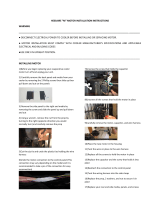
Remove pan support, burner head and aluminium bezel.
Place extended socket down main burner body centre. Undo and carefully remove injector.
Replace in reverse order.
3.9 OPEN TOP PRESSURE GOVERNOR (G2102 Only)
The type of governor used is maintenance free. Check that blue dust cap for the vent is fitted and in good repair. This
will protect the breather hole.
3.10 OVEN DOOR SWITCH
To gain access, proceed as follows:
Withdraw control panel.
Remove screws holding microswitch bracket and withdraw switch by moving it down and forward. Note wire
location and pull off connectors.
Remove microswitch from bracket.
Replace all parts in reverse order.
Note - The trip lever bracket holes are slotted to enable switch operation to be adjusted with respect to degree of
door opening. Adjust so that fan goes off when centre edge of door is open approx. 100mm. Apply a few drops of oil
to trip lever bearing occasionally.
3.11 OVEN LIGHT
To replace bulb, proceed as follows:
From inside oven, undo lens fixings and remove lens.
Unscrew bulb, taking care not to let it fall down behind oven back panel.
Fit new bulb and replace lens.
The correct type of bulb must be used.
3.12 OVEN FAN
This is removed from inside oven compartment, as follows:
Remove oven grid shelves and any loose items.
Remove oven chamber back panel as detailed in Section 3.2.4.
Remove fixings around fan back panel insert.
Remove nuts from studs around inner periphery and break seal around the edge.
Using two handles, pull fan assembly forward onto base of oven.
Remove wires from fan motor terminals, previously noting location of numbered wires and withdraw assembly clear
of the oven.
Dismantle inner fan from shaft by removing centre fixing screw and pulling fan off.
Remove motor by undoing 4 slotted screws (1 per leg of spider mounting).
Re-fit replacement motor in reverse order. Ensure mounting plate is properly resealed using a high temperature,
food contact safe sealant. e.g Ambersil.
Note - Do not fit inner fan from one motor on to another. Doing so is likely to result in assembly being imbalanced,
causing vibration and excessive noise.
When fitting fan to shaft, ensure pin in shaft is engaged in mating slot in fan boss.
3.13 CAPACITOR
To replace, proceed as follows:
Remove RH side panel (as Section 3.2.5).
Disconnect capacitor connections at terminal block mounted on panel, first noting the positions.
Remove hex nut at rear of capacitor and remove capacitor.
Replace in reverse order.
3.14 BUZZER
To replace, proceed as follows:
Withdraw control panel (as Section 3.2.1) and undo fixings for burner chamber grille.
Undo floor bracket fixing.
Remove buzzer fixing to bracket and disconnect electrical connections.
Replace in reverse order.
3.15 NEONS
Open oven control panel as detailed in Section 3.2.1.
Disconnect wiring and push neon out of location.
Replace in reverse order.
3.16 OVEN LIGHT PUSH BUTTON
Open oven control panel as detailed in Section 3.2.1.
Remove push-on connectors at rear.
Undo rear fixing nut and remove.
Replace in reverse order.
3.17 OVEN THERMOSTAT
Open oven control panel as detailed in Section 3.2.1.
Pull electrical connections off at rear and control knob from front.
Undo control panel fixings.
Open oven doors and remove grid shelves.
Remove RH side panel from oven as detailed in Section 3.2.4 thus revealing thermostat phial. Remove clips
securing phial. Also slacken clip which retains capillary tube to inside wall of controls compartment.
Withdraw thermostat, feeding capillary tube and phial through hole in oven wall.
Replace in reverse order, taking care to replace insulating sleeving on the capillary tube, and to coil excess tubing out
of the way of live parts.
Note
Re-calibration of thermostat requires use of a special tool, and therefore, cannot be undertaken other than by
qualified personnel.
3.18 POWER SWITCH
Open oven control panel as detailed in Section 3.2.1.
Pull off rear connections. Compress plastic securing tabs, enabling switch to be withdrawn from front.
To replace, simply push switch into hole, ensuring it is the correct way up. The locating tabs automatically spring into
position.
3.19 TIMER
Open oven control panel as detailed in Section 3.2.1.
Remove push-on connections at rear. Pull off control knob and undo fixings holding timer to panel.
Replace in reverse order.
3.20 OVEN FUSE
Open oven control panel as detailed in Section 3.2.1.
The fuse is located upon oven control panel side tray.
Lift off cover to replace fuse.
To replace fuse holder, RH side panel must be removed as detailed in Section 3.2.5. Remove fuse and undo centre
fixing.
3.21 OVEN DOOR SEAL
Seal is fixed to door frame with special spring clips. To remove, simply ease clips from holes.
Replacement seals are supplied with clips fixed to seal ready for insertion in holes in frame. Seal ends are inserted
into large holes at door frame corners. After fitting replacement seal, check it closes effectively at all points,
although minor gaps and cracks can be tolerated without affecting performance. If necessary, door fit and ball
catch can be adjusted by removal or addition of shims under hinge brackets and ball catch keeper plate.
To gain access to brackets and keeper, it is necessary to remove trim immediately above doors and lower grille.
Adjust shims as necessary to produce necessary fit, endeavouring to achieve all-round seal contact.
The ball catch keeper is adjusted by adding or removing shims so the doors are held positively closed with ball
exerting a slight pressure tending to close them. Also check when oven is hot.
Shims have slotted holes, therefore it is only necessary to slacken respective fixings in order to remove or replace
them.
SECTION 4 – SPARES
When ordering any spare parts always quote the appliance type and serial number. This information will be found on
the data plate attached to the side of the control compartment.
A short list of spare parts is included in the user manual.
G2112/2102 Wiring Diagram
  • Page 1 1
  • Page 2 2
  • Page 3 3
  • Page 4 4
  • Page 5 5
  • Page 6 6
  • Page 7 7
  • Page 8 8
  • Page 9 9
  • Page 10 10
  • Page 11 11
  • Page 12 12
  • Page 13 13
  • Page 14 14
  • Page 15 15
  • Page 16 16

Falcon G2102 Installation And Servicing Instructions

Category
Ovens
Type
Installation And Servicing Instructions
This manual is also suitable for

Ask a question and I''ll find the answer in the document

Finding information in a document is now easier with AI