Page is loading ...

Operating instructions
Heating controller
QRK 201 F001
7 000458 003 H2
R
7 000458 003

You have opted for a Sauter control unit, a quality product from a leading manufacturer of control devices for heating, ventilation
and air conditioning.
Your new device features simple operation in connection with advanced micro-processor technology. Please follow operating
instructions for adapting the device to your specific system and requirements
.
Due to its automatic change-over between summer and winter modes (and vice-versa), its automatic weather compensation and
adaptation to building characteristics and heating systems, the individually programmable time programs for controlling the nightly
temperature reduction, domestic hot water charge etc, optimisation of ON/OFF switching time sections for normal and nightly tem-
perature and controlled booster pre-heating mode, this device enables consequent energy saving programs to be implemented
while simultaneously ensuring high comfort. The quartz clock of the controller has an automatic summertime/wintertime change-over
system and works without environmentally unfavourable batteries or accumulators.
Due to a high flexibility of the input and output configuration, this controller can be adapted perfectly to different types of heating
systems; demand-led heating circulation pumps (with speed reduction control), domestic hot-water charge pumps and general circu-
lation pumps can be controlled in addition to one or two three-point control valves. The controller measures all parameters relevant
for an efficient heating system control by means of up to eight "Nickel 1000" temperature sensors and additional special inputs for
flow measurement with three optional methods.
The controller can be configured and programmed on site without any additional accessories; it can also be adapted to an extended
range of tasks at a later time.
The exceptionally high number of functions includes safety features such as the system frost-protection function which is activated
in OFF mode, standstill-damage protection of the circulation pumps during summer, anti-legionella function for hygienically unob-
jectionable hot water, minimum and maximum limitation of temperatures and flow, etc.
With the optional remote control accessory, the heating controller can be operated from up to two independent homes or offices.
R
7 000458 003

Table of contents
User information
. . . . . . . . . . . . . . . . . . . . . . . . . . . . . . . . . . . . . . . . . . . . . . . . . . . . . . . . . . . . . . . . . . . . . . . . . . . . . . . . . . . . 3
Controller front view . . . . . . . . . . . . . . . . . . . . . . . . . . . . . . . . . . . . . . . . . . . . . . . . . . . . . . . . . . . . . . . . . . . . . . . . . . . . . . . . . . . 3
–
Operating elements . . . . . . . . . . . . . . . . . . . . . . . . . . . . . . . . . . . . . . . . . . . . . . . . . . . . . . . . . . . . . . . . . . . . . . . . . . . . . . 3
The information centre . . . . . . . . . . . . . . . . . . . . . . . . . . . . . . . . . . . . . . . . . . . . . . . . . . . . . . . . . . . . . . . . . . . . . . . . . . . . . . . . . 4
–
Heating modes . . . . . . . . . . . . . . . . . . . . . . . . . . . . . . . . . . . . . . . . . . . . . . . . . . . . . . . . . . . . . . . . . . . . . . . . . . . . . . . . . . 4
–
Domestic hot-water modes. . . . . . . . . . . . . . . . . . . . . . . . . . . . . . . . . . . . . . . . . . . . . . . . . . . . . . . . . . . . . . . . . . . . . . . . . 4
–
Special conditions. . . . . . . . . . . . . . . . . . . . . . . . . . . . . . . . . . . . . . . . . . . . . . . . . . . . . . . . . . . . . . . . . . . . . . . . . . . . . . . . 5
–
Outputs . . . . . . . . . . . . . . . . . . . . . . . . . . . . . . . . . . . . . . . . . . . . . . . . . . . . . . . . . . . . . . . . . . . . . . . . . . . . . . . . . . . . . . . . 5
–
Control values. . . . . . . . . . . . . . . . . . . . . . . . . . . . . . . . . . . . . . . . . . . . . . . . . . . . . . . . . . . . . . . . . . . . . . . . . . . . . . . . . . . 6
Frequently used abbreviations. . . . . . . . . . . . . . . . . . . . . . . . . . . . . . . . . . . . . . . . . . . . . . . . . . . . . . . . . . . . . . . . . . . . . . . . . . . 8
Factory settings . . . . . . . . . . . . . . . . . . . . . . . . . . . . . . . . . . . . . . . . . . . . . . . . . . . . . . . . . . . . . . . . . . . . . . . . . . . . . . . . . . . . . . 9
SET
time operations . . . . . . . . . . . . . . . . . . . . . . . . . . . . . . . . . . . . . . . . . . . . . . . . . . . . . . . . . . . . . . . . . . . . . . . . . . . . . . . . . . 9
–
Setting the day of the week and the time . . . . . . . . . . . . . . . . . . . . . . . . . . . . . . . . . . . . . . . . . . . . . . . . . . . . . . . . . . . . . . 9
–
Setting year and date . . . . . . . . . . . . . . . . . . . . . . . . . . . . . . . . . . . . . . . . . . . . . . . . . . . . . . . . . . . . . . . . . . . . . . . . . . . . 10
–
Activating the wintertime/summertime change-over . . . . . . . . . . . . . . . . . . . . . . . . . . . . . . . . . . . . . . . . . . . . . . . . . . . . 10
–
Activating the summertime/wintertime change-over . . . . . . . . . . . . . . . . . . . . . . . . . . . . . . . . . . . . . . . . . . . . . . . . . . . . 10
Selection of operating mode (heating and domestic hot water) . . . . . . . . . . . . . . . . . . . . . . . . . . . . . . . . . . . . . . . . . . . . . . . . 11
Short-term interruption of the weekly program . . . . . . . . . . . . . . . . . . . . . . . . . . . . . . . . . . . . . . . . . . . . . . . . . . . . . . . . . . . . . 12
Party function . . . . . . . . . . . . . . . . . . . . . . . . . . . . . . . . . . . . . . . . . . . . . . . . . . . . . . . . . . . . . . . . . . . . . . . . . . . . . . . . . . . . . . . 12
Adapting the heating characteristic . . . . . . . . . . . . . . . . . . . . . . . . . . . . . . . . . . . . . . . . . . . . . . . . . . . . . . . . . . . . . . . . . . . . . . 13
Adapting the normal temperature setpoint. . . . . . . . . . . . . . . . . . . . . . . . . . . . . . . . . . . . . . . . . . . . . . . . . . . . . . . . . . . . . . . . . 14
Tips for energy saving . . . . . . . . . . . . . . . . . . . . . . . . . . . . . . . . . . . . . . . . . . . . . . . . . . . . . . . . . . . . . . . . . . . . . . . . . . . . . . . . 14
PRO
time programs . . . . . . . . . . . . . . . . . . . . . . . . . . . . . . . . . . . . . . . . . . . . . . . . . . . . . . . . . . . . . . . . . . . . . . . . . . . . . . . . . . 15
–
Timer. . . . . . . . . . . . . . . . . . . . . . . . . . . . . . . . . . . . . . . . . . . . . . . . . . . . . . . . . . . . . . . . . . . . . . . . . . . . . . . . . . . . . . . . . 17
–
Weekly program . . . . . . . . . . . . . . . . . . . . . . . . . . . . . . . . . . . . . . . . . . . . . . . . . . . . . . . . . . . . . . . . . . . . . . . . . . . . . . . . 18
–
Annual program . . . . . . . . . . . . . . . . . . . . . . . . . . . . . . . . . . . . . . . . . . . . . . . . . . . . . . . . . . . . . . . . . . . . . . . . . . . . . . . . 19
Switching-time optimisation . . . . . . . . . . . . . . . . . . . . . . . . . . . . . . . . . . . . . . . . . . . . . . . . . . . . . . . . . . . . . . . . . . . . . . . . . . . . 19
Inquiry and adaptation of user adjustment values
PAR
(parameters) . . . . . . . . . . . . . . . . . . . . . . . . . . . . . . . . . . . . . . . . . . . 20
Hand switch, emergency operation . . . . . . . . . . . . . . . . . . . . . . . . . . . . . . . . . . . . . . . . . . . . . . . . . . . . . . . . . . . . . . . . . . . . . . 23
Automatic switch-off/switch-on (daily heating limit, summer/winter) . . . . . . . . . . . . . . . . . . . . . . . . . . . . . . . . . . . . . . . . . . . . . 23
Manual activation of winter mode . . . . . . . . . . . . . . . . . . . . . . . . . . . . . . . . . . . . . . . . . . . . . . . . . . . . . . . . . . . . . . . . . . . . . . . 24
Manual activation of summer mode. . . . . . . . . . . . . . . . . . . . . . . . . . . . . . . . . . . . . . . . . . . . . . . . . . . . . . . . . . . . . . . . . . . . . . 24
Frost-protection function . . . . . . . . . . . . . . . . . . . . . . . . . . . . . . . . . . . . . . . . . . . . . . . . . . . . . . . . . . . . . . . . . . . . . . . . . . . . . . 24
Pump control . . . . . . . . . . . . . . . . . . . . . . . . . . . . . . . . . . . . . . . . . . . . . . . . . . . . . . . . . . . . . . . . . . . . . . . . . . . . . . . . . . . . . . . 24
Anti-jamming function . . . . . . . . . . . . . . . . . . . . . . . . . . . . . . . . . . . . . . . . . . . . . . . . . . . . . . . . . . . . . . . . . . . . . . . . . . . . . . . . 24
Mains power failure . . . . . . . . . . . . . . . . . . . . . . . . . . . . . . . . . . . . . . . . . . . . . . . . . . . . . . . . . . . . . . . . . . . . . . . . . . . . . . . . . . 24
Accessories . . . . . . . . . . . . . . . . . . . . . . . . . . . . . . . . . . . . . . . . . . . . . . . . . . . . . . . . . . . . . . . . . . . . . . . . . . . . . . . . . . . . . . . . 25
–
Room-temperature sensor EGT 320 . . . . . . . . . . . . . . . . . . . . . . . . . . . . . . . . . . . . . . . . . . . . . . . . . . . . . . . . . . . . . . . . 25
–
Remote-control unit EGS 52/15 . . . . . . . . . . . . . . . . . . . . . . . . . . . . . . . . . . . . . . . . . . . . . . . . . . . . . . . . . . . . . . . . . . . . 25
Malfunctions . . . . . . . . . . . . . . . . . . . . . . . . . . . . . . . . . . . . . . . . . . . . . . . . . . . . . . . . . . . . . . . . . . . . . . . . . . . . . . . . . . . . . . . . 25
Specialist’s information
. . . . . . . . . . . . . . . . . . . . . . . . . . . . . . . . . . . . . . . . . . . . . . . . . . . . . . . . . . . . . . . . . . . . . . . . . . . . . 26
SERV service settings . . . . . . . . . . . . . . . . . . . . . . . . . . . . . . . . . . . . . . . . . . . . . . . . . . . . . . . . . . . . . . . . . . . . . . . . . . . . . . . . 26
–
Output status configuration in manual operation . . . . . . . . . . . . . . . . . . . . . . . . . . . . . . . . . . . . . . . . . . . . . . . . . . . . . . . 27
–
3-point output configuration . . . . . . . . . . . . . . . . . . . . . . . . . . . . . . . . . . . . . . . . . . . . . . . . . . . . . . . . . . . . . . . . . . . . . . . 28
–
2-point output configuration, pump follow-up . . . . . . . . . . . . . . . . . . . . . . . . . . . . . . . . . . . . . . . . . . . . . . . . . . . . . . . . . . 29
R
–
1
–
7 000458 003

–
Calibration of the temperature and flow inputs . . . . . . . . . . . . . . . . . . . . . . . . . . . . . . . . . . . . . . . . . . . . . . . . . . . . . . . . 30
–
Configuration of binary and temperature inputs. . . . . . . . . . . . . . . . . . . . . . . . . . . . . . . . . . . . . . . . . . . . . . . . . . . . . . . . 33
–
Flow rate and return temperature limitation . . . . . . . . . . . . . . . . . . . . . . . . . . . . . . . . . . . . . . . . . . . . . . . . . . . . . . . . . . . 36
–
Closed-loop control via final control element V1 . . . . . . . . . . . . . . . . . . . . . . . . . . . . . . . . . . . . . . . . . . . . . . . . . . . . . . . 38
–
Closed-loop control via final control element V2 . . . . . . . . . . . . . . . . . . . . . . . . . . . . . . . . . . . . . . . . . . . . . . . . . . . . . . . 39
–
Heating system, building and air conditioning . . . . . . . . . . . . . . . . . . . . . . . . . . . . . . . . . . . . . . . . . . . . . . . . . . . . . . . . . 40
–
Heating characteristic 1 (for heating circuit 1) . . . . . . . . . . . . . . . . . . . . . . . . . . . . . . . . . . . . . . . . . . . . . . . . . . . . . . . . . 41
–
Heating characteristic 2 (for heating circuit 2) . . . . . . . . . . . . . . . . . . . . . . . . . . . . . . . . . . . . . . . . . . . . . . . . . . . . . . . . . 42
–
Limits for heating characteristic 1 (heating circuit 1) . . . . . . . . . . . . . . . . . . . . . . . . . . . . . . . . . . . . . . . . . . . . . . . . . . . . 42
–
Limits for heating characteristic 2 (heating circuit 2) . . . . . . . . . . . . . . . . . . . . . . . . . . . . . . . . . . . . . . . . . . . . . . . . . . . . 43
–
Type of building . . . . . . . . . . . . . . . . . . . . . . . . . . . . . . . . . . . . . . . . . . . . . . . . . . . . . . . . . . . . . . . . . . . . . . . . . . . . . . . . 43
–
Switching-time optimisation . . . . . . . . . . . . . . . . . . . . . . . . . . . . . . . . . . . . . . . . . . . . . . . . . . . . . . . . . . . . . . . . . . . . . . . 44
–
Adaptation of heating characteristic(s). . . . . . . . . . . . . . . . . . . . . . . . . . . . . . . . . . . . . . . . . . . . . . . . . . . . . . . . . . . . . . . 46
–
Domestic hot water. . . . . . . . . . . . . . . . . . . . . . . . . . . . . . . . . . . . . . . . . . . . . . . . . . . . . . . . . . . . . . . . . . . . . . . . . . . . . . 47
–
Pre-control . . . . . . . . . . . . . . . . . . . . . . . . . . . . . . . . . . . . . . . . . . . . . . . . . . . . . . . . . . . . . . . . . . . . . . . . . . . . . . . . . . . . 48
Characteristic curves for heating and domestic hot water . . . . . . . . . . . . . . . . . . . . . . . . . . . . . . . . . . . . . . . . . . . . . . . . . . . . 49
Resistance values of the temperature sensors . . . . . . . . . . . . . . . . . . . . . . . . . . . . . . . . . . . . . . . . . . . . . . . . . . . . . . . . . . . . . 50
Wiring diagram. . . . . . . . . . . . . . . . . . . . . . . . . . . . . . . . . . . . . . . . . . . . . . . . . . . . . . . . . . . . . . . . . . . . . . . . . . . . . . . . . . . . . . 50
Record sheets
–
Weekly and annual switching program . . . . . . . . . . . . . . . . . . . . . . . . . . . . . . . . . . . . . . . . . . . . . . . . . . . . . . . . . . . . . . 51
–
Configuration sheet . . . . . . . . . . . . . . . . . . . . . . . . . . . . . . . . . . . . . . . . . . . . . . . . . . . . . . . . . . . . . . . . . . . . . . . . . . . . . 54
Index
. . . . . . . . . . . . . . . . . . . . . . . . . . . . . . . . . . . . . . . . . . . . . . . . . . . . . . . . . . . . . . . . . . . . . . . . . . . . . . . . . . . . . . . . . . 58
R
–
2
–
7 000458 003

User information
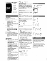
Controller front view
Information panel Operating keys
Slide switch
Service and adaptor keypad
SETPROPAR SERV
SERV
Normal operation
Reduced operation
OFF mode
Party
Short-term presence/absence
Automatic operation acc. to time program
Normal-temperature setpoint
(= PAR 1)
Forward
Return
Numerical keypad
Clearing and preparation of a new entry
Control parameter entry
Time program entry
Entry of day of the week,
time and date
Service
Domestic-hot-water system disabled
Domestic-hot-water system enabled
Annual program in conjunction
with PRO key
. . .
PAR
PRO
SET
User keypad with function keys Service and adjustment keypad
Operating-mode switch
Operating elements
1
AUTO
2
2
AUTO
Incrementation keys
1
B01493
Manual operation
Automatic operation
Service
Interface RS 232
R
–
3
–
7 000458 003

The information centre (LCD)
This display unit provides information on the current operating status of the heating system. Flashing symbols prompt parameter
entry or indicate a special operating condition and are designated with the symbol in the following text. means factory
setting of the controller.
Heating modes
If no "upper" clock symbol is shown in conjunction with the
display of the current operating mode, this indicates either con-
tinuous operating of heating circuit 1 or timer-controlled opera-
tion.
When 2 heating circuits are configured, the operating mode of
the second heating circuit will be indicated by a flashing symbol
if different from the operating mode of the first heating circuit.
The "upper" clock symbol is only displayed for heating
circuit 1.
Operating modes for domestic hot water
If no "lower" clock symbol is shown in conjunction with the
display of the current operating mode, this indicates either con-
tinuous operation of the domestic-hot-water system or timer-
controlled operation.
12
3
2
0
I
2
2
2
LIM
OPT
2
SET
PRO
PAR SERV
m /h
3
d
°C
B01494
. . .
(
upper
)
Heating operation controlled by weekly program
(
upper)
Heating operation controlled by annual program
Heating operation controlled by timer (without upper clock symbol)
Normal operation
Reduced operation
Off mode
(
lower
)
Domestic-hot-water operation controlled by weekly program
(
lower
)
Domestic-hot-water operation controlled by annual program
Domestic-hot-water operation controlled by timer control (without lower clock symbol)
Domestic-hot-water heating disabled
Domestic-hot-water heating enabled (setpoint 1)
Domestic-hot-water heating enabled (setpoint 2)
Heating
Domestic hot water
R
–
4
–
7 000458 003

Special conditions
Outputs
External temperature below freezing (frost-protection function will be activated as required)
Optimised heating phase
Optimised temperature reduction/switch-off phase
Flow or return-temperature limiting function has been triggered
Emergency operation: flow transmitter defective
Valve 1 opens
Time-channel contact to exterior is open (will
only be displayed for creating the corresponding
time program)
Valve 1 closes Time-channel contact to exterior closed
Valve 2 opens Charge pump for domestic hot water on
Valve 2 closes Circulation pump for domestic hot water on
Circulation pump of heating circuit 1 on
Charge pump 2 on
Circulation pump of heating circuit 2 on
Internal circulation pump (secondary) on
Speed-reduction output for
circulation pump of heating circuit 1 switched on
OPTEIN output on
Speed-reduction output for
circulation pump of heating circuit 2 switched on
Heat demand
OPT
OPT
LIM
LIM
0
I
2
2
2
2
3
OPT
2
R
–
5
–
7 000458 003

Control values
In closed-loop operation, several values can be inquired or dis-
played continuously.
The display can be changed by means of the incrementation
keys (forward) and (return).
A thermometer symbol is always shown in conjunction with a
temperature setpoint; a flashing thermometer symbol indicates
an
actual temperature value.
Year/month/date of the digital clock (from the controller)
B07565
2
Weekday and time of the digital clock
Actual value of ouside temperature
Actual value of room temperature
Setpoint for room temperature
Actual value of room temperature
Setpoint for room temperature
Actual value of DHW temperature
(upper)
Setpoint for DHW temperature
Actual value of DHW temperature
(lower)
DHW
Heating circuit 2
Heating circuit 1
R
–
6
–
7 000458 003

Flow temperature setpoint
Actual return temperature
Return temperature limitation setpoint
Actual flow temperature
Flow temperature setpoint
Flow temperature setpoint regulated
by valve V2
Primary flow rate, max. limit
regulated
by valve V2
m /h
3
m /h
3
m /h
3
2
2
2
Actual return temperature
Return temperature limitation setpoint
Primary flow rate, actual value
Primary flow rate, min. limit
regulated
by valve V1
flow rate
Actual flow temperature
2
R
–
7
–
7 000458 003

Frequently used abbreviations
Temperatures
T
A
= outdoor temperature
T
F
= flow temperature
T
FS
= flow-temperature setpoint
T
FS(W)
= flow-temperature setpoint during domestic-hot-water
charge
T
I
= base point (initial point) of the heating curve
T
R
= room temperature
T
RS
= room-temperature setpoint
T
RF
= return temperature
T
RFS
= return-temperature setpoint
T
W
= domestic-hot-water temperature
T
WS
= setpoint of domestic-hot-water temperature
Control parameters
S = slope of heating characteristic
t
N
= reset time
X
p
= proportional band
X
sh
= neutral zone
X
sd
= switching differential
X
sd(w)
= switching differential for domestic hot water tank
Other abbreviations
BW = domestic (hot) water
KW = cold water
HE, HA = auxiliary contacts of the valve actuator which is
closed above or below a certain valve travel/value
flow rate
HK.. = heating circuit..
I.. = input..
O.. = output..
LP.. = charge pump .. for domestic hot water
UP.. = circulation pump .. (heating)
ZP = circulation pump for domestic hot water
t
AK
= building (cooling) time constant
V.. = valve/final control element ..
F=flow rate
R
–
8
–
7 000458 003

Factory setting
The factory settings ( ) refer to an average building and a
common system layout.
You can, of course, adpat all settings quickly and easily to
your specific requirements.
Day of the week and time SET
3 12.03 Wednesday 12:03; after the initial switch-on
a random value is shown here for the day
of the week and for the time.
Year and date
90 01.01 January 1, 1990
Date for switching from wintertime to summertime
03.25 March 25
Date for switching from summertime to wintertime
10.25 October 25
Weekly program PRO 1 for heating circuit 1
No enable/disable commands are programmed for the domestic
hot water supply in the factory settings. This means that do-
mestic hot water is heated at any time if required.
See section PAR... for factory settings of user adjustment values
See section SERV... for factory settings of service adjustment
values.
SET time operations
Setting the day of the week and the time
Example: the current day of the week is Tuesday (2nd day of the week), the time is 09:14 am.
PRO 1 0 06:00 Daily normal operation
0 22:00 from 6:00 am to 22:00 pm
6 07:00 Normal operation on Saturdays
6 23:00 from 7:00 am to 23:00 pm
7 07:00 Normal operation on Sundays
7 22:00 from 7:00 am to 22:00 pm
Key Display Explanation
1 23:45
SET mode selected, display shows the current values for day of the week and controller time
– – –:– –
Invalid day of week and time cleared (if required)
2 09:14
Enter valid day of week (2 = Tuesday) and valid time (09:14 = 9:14 am)
1 = Monday 3 = Wednesday 5 = Friday
2 = Tuesday 4 = Thursday 6 = Saturday
7 = Sunday
SET
8
2
0
9
1
4
R
–
9
–
7 000458 003

Setting year and date
Activating the wintertime/summertime change-over
According to the change-over dates entered in the factory
settings, the seasonal time changeover will automatically take
place during the last Sunday of march/october. The change over
takes place on the Sunday following the change-over date, at
02 o’clock am. If other change-over times are required, these
settings can be implemented as follows:
Activating the summertime/wintertime change-over
Key Display Explanation
e. g. 1 23:45 SET mode selected, display shows day of the week and time
e. g. 93 10.18 Select controller date (year/month/day)
– – –:– – Invalid date cleared
e. g. 93 11.27 Enter valid date (year/month/day)
Key Display Explanation
e. g. 1 23:45 SET mode selected, display shows day of the week and time
2×
e. g. 03.25 Date (month/day) for wintertime/summertime change-over (h+)
– –.– –
Clear invalid date
e. g. 04.01 Enter valid date (month/day)
Key Display Explanation
e. g. 1 23:45
SET mode selected, display shows day of the week and time
3×
e. g. 10.25
Date (month/day) for summertime/wintertime change-over (h-)
– –.– –
Clear invalid date
e. g. 10.01
Enter valid date (month/day)
SET
8
9
3
1
1
2
7
SET
8
0
3
2
7
SET
8
0
9
2
6
R
–
10
–
7 000458 003

Selecting the operating mode (heating and domestic hot water)
By pressing one of the keys shown below, you can select the following modes of operation:
The clock symbol is never used for heating circuit 2; here only
the current operating mode is displayed. A flashing operating
mode symbol ( , , ) always refers to heating circuit 2. If
the operating modes ( , , ) are the same for both heating
circuits, the corresponding symbol is shown continuously.
If, in addition, a remote control device is installed, this device will
only act on one heating circuit. An additional remote-control unit
must be installed for the second heating circuit, if required. Re-
mote control has priority only when the controller is in automatic
mode PRO 1 or 2.
Automatic mode:
Heating operation and enabling/disabling the charge of domestic water is controlled according to
the time program as specified in PRO 0...2. If further time channels have been configured in PRO 0...2, they will
also be operated according to this time program.
Heating system in
continuous
normal operation (upper symbol disappears from the display)
If an additional heating circuit is installed, the operator must specify whether the entry is valid for heating
circuit 1 or heating circuit 2 after pressing the key.
This is effected by means of key for heating circuit 1 or for heating circuit 2.
The operating mode of the heating circuit not addressed by the entry remains unchanged.
If the key is pressed instead of or , both circuits will be switched to winter operation.
Heating system in
continuous
reduced operation (upper symbol disappears from the display)
If an additional heating circuit is installed, the operator must specify whether the entry is valid for heating
circuit 1 or heating circuit 2 after pressing the key.
This is effected by means of key for heating circuit 1 or heating circuit 2.
The operating mode of the heating circuit not addressed by the entry remains unchanged.
If the key is pressed instead of or , both circuits will be switched to winter operation.
Heating
continuously
switched off (upper symbol disappears from the display). The
frost protection function
will reliably prevent damage to the heating system when outdoor temperature drops below freezing point.
If an additional heating circuit is installed, the operator must specify whether the entry is valid for heating
circuit 1 or heating circuit 2 after pressing the key.
This is effected by means of key for heating circuit 1 or for heating circuit 2.
The operating mode of the heating circuit not addressed by the entry remains unchanged.
If the key is pressed instead of or , both circuits will be switched to summer operation.
Single immediate
charging of the domestic-hot-water-tank. This is also possible during periods in which the hot
water system is disabled if the domestic-hot-water-temperature lies below the setpoint (SERV 90).
Domestic-hot-water charging continuously disabled
(lower symbol disappears from the display) or
interruption of single immediate charging.
1
2
1
2
1
1
2
2
1
2
1
1
2
2
1
2
1
1
2
1
0
R
–
11
–
7 000458 003

Short interruption of the weekly heating program
After the switching command (in our example at 10:00 pm) following A, the heating operation will return to the weekly program.
Party function
(Please note: The switching command 7 23:30 has been entered in addition to the factory-set weekly program)
(without previous actuation of or ) results in a RESET
command for the party function and the short-term absence/pre-
sence function. These two functions can only be activated for
heating circuit 1 and 2 if the selected heating circuit is in winter
operation and operation is controlled by the weekly program.
When operation is controlled by the weekly program, the operating mode can be changed until the next switching com-
mand is released. The operating modes are switched according to the symbols printed on the keys.
If a second heating circuit is installed, the operator must specify whether the entry is valid for heating
circuit 1 or heating circuit 2 after pressing the yellow key. This is effected by means of key for heating
circuit 1 and for heating circuit 2.
Example: 0 06:00 , 0 22:00 ; the house is left at time A with the intention of returning late at night.
06:00 22:00 06:00
06:00 22:00 06:00A
A
1 x
Prematurely reduced heating operation
06:00 22:00 06:00A
Heating OFF until the next switching
command is released
or
2 x
B01530
When operation is controlled by the weekly program, the next switching command will not be executed. After the key
has been pressed, the symbol in the display will flash. The function is cancelled when the same key is pressed
again.
If an additional second heating circuit is installed, the operator must specify whether the entry is valid for heating
circuit 1 or heating circuit 2 after pressing the yellow key. This is effected by means of key for heating
circuit 1 and for heating circuit 2.
07:00 23:00 07:00
07:00
No change-over to ,
B01531
23:00 07:00
Example 2: Sunday 7 07:00 , 7 22:00 , 7 23:30
07:00 23:30 06:00
07:00
22:00
23:30 06:0022:00
Example 1: Saturday 6 07:00 , 6 23:00
Change-over to ,
at a later time
1
2
1
2
1
2
1
2
R
–
12
–
7 000458 003

Adapting the heating characteristic
A properly adapted heating characteristic results in a constant
room temperature even with varying outdoor temperatures. The
factory settings of the controller heating characteristic are de-
signed for an average building with radiator heating. If no room-
temperature sensor is available or if the reference room is not
typical for the entire building, the heating characteristic can be
adapted
manually
(see below for automatic correction). If the
set normal temperature (user adjustment value PAR no. 1) is not
reached after a couple days, corrections can be entered as fol-
lows (example for heating circuit 1):
Correct: PAR no. 1 in steps of 0.5 °C max. and PAR no. 3 in
steps of 0.05 max. until the desired normal temperature is
reached. If possible, introduce only one change per day in order
to give the building time to adjust to the new condition.
If there is a second heating circuit, the same applies with the ap-
propriate parameters:
PAR 7 = normal temperature of heating circuit 2
PAR 9 = curve slope of heating circuit 2
and for the corresponding SERV adjustment values.
If a room-temperature sensor is available in a typical room
(reference room) of the building, an
automatic
adaptation of the
heating characteristic can be triggered via setting value
SERV 88.
It is essential for this mode that any thermostat valves installed
in this room remain in their fully open position.
By means of the measured deviations of the room temperature
from the corresponding setpoint and the average outdoor tem-
perature calculated for the measuring period, the system will
either.
•
adjust the slope of the heating characteristic (PAR 3);
or
•
adjust the curvature factor of the heating characteristic
(SERV 66);
or
•
shift the base point of the heating characteristic
(= external heat supply) horizontally.
The number of adaption steps executed is shown under
SERV 88
The automatic adaption of the heating characteristic parameters
is executed with high weighting factors for the first adaption steps
(if a deviation has been detected) and with reduced weighting
for the subsequent adaption steps.
Observation Action
Normal temperature
too high
during warm
and cold
weather
Reduce normal temperature PAR no. 1
during warm
weather only
Reduce normal temperature (PAR no. 1) and increase slope
of heating characteristic (PAR no. 3)
during cold
weather only
Reduce slope of heating characteristic (PAR no. 3)
Normal temperature
too low
during warm
and cold
weather
Increase normal temperature (PAR no. 1)
during warm
weather only
Increase normal temperature (PAR no. 1) and reduce slope of
heating characteristic (PAR no. 3)
during cold
weather only
Increase slope of heating characteristic (PAR no. 3)
B01093
B01096
B01098
B01099
B01100
B01101
R
–
13
–
7 000458 003

Adapting the normal-temperature setpoint
Normal temperature can easily be changed by pressing the keys shown above (see also PAR 1 and 7). If a second heating circuit
is installed, the operator must specify whether the entry is valid for heating circuit 1 or heating circuit 2 after pressing the
yellow key. This is effected by means of key for heating circuit 1 or for heating circuit 2.
Example:
Use these keys when the heating characteristic is adjusted properly and the normal temperature is to be increased or reduced
(please refer also to the section on remote control EGS 52/15)
Tips for energy saving
Your heating system controller has been designed according to
state-of-the art principles of energy saving. Your management
of the heating system is, however, also important.
•
The highest savings are possible when the heating
system is switched off during the night. Normal buildings
(of medium-heavy construction and average-type insu-
lation) cool down by 2...3 °C when the heating is
switched off for between 8 and 10 hours. Try to comple-
tely switch off the heating system over night ( instead
of reduced operation ). The integrated frost protection
function will reliably prevent freezing of system compo-
nents.
•
Can the switching times of the weekly program for or
operation be advanced?
•
Heat to temperatures between 19 °C and 21 °C.
Each additional degree increases the heating costs by
approx. 6 %.
•
Air the rooms only for short periods (5 min) but with wide
open windows and, if possible, across the room.
•
The radiator-thermostat valve can be partially closed in
rooms not being used for a considerable period of time
(except for the reference room).
•
Close window shutters and curtains at night.
•
Curtains hanging over the radiators reduce their efficien-
cy and result in increased energy consumption.
•
Switch the heating system to reduced temperature ( )
or OFF ( ), when you leave the house for several
hours. Use the short-term absence key for this
purpose.
B01532
2
1
2
±
0.5 °C per depression
B01533
R
–
14
–
7 000458 003

PRO time programs
Dependent on the corresponding system configuration, the com-
ponents of the system can be controlled individually. By pressing
one of the yellow keys of the user keypad, the controller is
switched to the corresponding continuous operating mode (refer
to the section on operating mode selection). The controller nor-
mally operates in mode. By suitably programming the time
programs PRO 0...2, several components of the system can be
triggered once (timer) or repeatedly (weekly and annual pro-
grams). The operating status of the system can be influenced
by several sources in the following manner:
Possible conflicts between the individual sources are solved by
different priorities assigned to the sources (Example: annual
program specifies: heating circuit 1 ON, weekly program spe-
cifies: circuit 1 OFF; the annual program has higher priority than
the weekly program, therefore heating circuit 1 is switched ON).
The timer has the highest priority; it can therefore not be inter-
rupted by the continuous operating mode (disabling is, however,
possible with PRO 0 = 000 (h)).
The controller has 3 time programs:
PRO 0: 1 timer (hourly count-down)
PRO 1: 1 weekly program with a maximum of
40 switching commands
PRO 2: 1 annual program with a maximum of
28 switching commands
SUBSYSTEM / TIME CHANNEL
Source Priority Key
PRO...
0
12
3
4
Auto. timer
999 h max.
1
(highest)
0
Continuous operating
mode
2
–– –
Ext. clock.
refer to SERV 19
3a
––
Autom. annual progr.
28 switching com-
mands max.
4
2
Autom. weekly progr.
40 switching com-
mands max.
5
(lowest)
1
possible operating status
0: Off
0:
0: Off
1: On
1:
1: On
2:
for annual program only:
subsequent operation according to weekly program
2
0
1 1
1
Individual weekly or annual programs can be entered in the record sheets attached at the end of these operating instructions.
R
–
15
–
7 000458 003

If two heating circuits are installed and if both circuit 1 and circuit
2 are supplied by the same heat exchanger (SERV 01 = +3),
heating circuit 1 always has priority *
)
. During operating pha-
ses for heating circuit 1, it is possible to run heating circuit 2 in
or mode, but not in mode. The setpoint of the secondary
flow temperature for the corresponding operating modes can be
seen in the following table:
Heating circuit 1
(HK1)
Heating circuit 2
(HK2)
Secondary
flow temperature
setpoint
Annual program, weekly program, timer, external clock, conti-
nuous operating mode, etc., have the following priorities:
Priority 1: Timer (highest priority)
Priority 2: Continuous operating mode
Priority 3a: External clock
Priority 3b: Remote control
Priority 4: Annual program
Priority 5: Weekly program (lowest priority)
*) Exception: Domestic hot water heating in parallel operation. In this case, the corresponding flow temperature setpoint applies
for domestic-hot-water heating.
After the key has been pressed, the automatic programs are generally displayed and entered in 3 steps:
Step 1:
Selecting the time program
Step 2:
Selecting the time channel
Step 2:
Selecting the operating status
2
2
2
7
PRO
Key Program
Timer
Weekly program
Annual program
Key Channel
External time channel
Heating circuit 1
Heating circuit 2
Domestic-hot-water circuit
Domestic-hot-water circuit
•
Heating circuit 1
•
Domestic hot water
– function heating disabled
– function heating enabled (setpoint 1)
– function heating enabled (setpoint 2)
•
Heating circuit 2
•
Time channel to exterior
– function
0
OFF
– function 1 ON
– function
•
Domestic-hot-water circ.
0
OFF
1
ON
0
1
2
0
0
1
2
2
3
4
0
1
2
0
1
0
1
R
–
16
–
7 000458 003

Timer PRO 0
Enables the operating status or mode to be specified for 1...999 hours (~ 40 days).
The timer function can then be activated for another time channel by using the same procedure.
Key Function Display
Set controller to time-program entry status
–
Select timer function
/ / / /
*)
Select time channel to be programmed:
e. g.
Heating circuit 2 (see above)
0 h
Clear displayed period
– – – h
e. g. ...
Enter required period,
027 h
e. g. for 27 h
Enter desired operating status or mode:
e. g.
reduced operation (see above)
Return to automatic operation
7
PRO
PRO
0
0
2
2
2 2
2
0 9
2
0
2
7
1
R
–
17
–
7 000458 003

Weekly program PRO 1
Up to 40 switching commands in total can be entered for the
existing time channels with time periods of up to one week.
The program is repeated every week.
Then, another time channel of the weekly program can be se-
lected by using the same procedure
The 40 switching commands of the weekly program can be
distributed among the configured time channels in any arrange-
ment.
For heating circuit 1, factory settings are entered into the weekly
program ( ) which can simply be adapted as required
(refer to factory settings).
The switching commands valid for daily actuation (0 hh:mm) are
not taken into account on special days (1...7 hh:mm).
*
)
Dependent on configuration
Key Function Display
Set controller to time-program entry status
–
Select weekly program
/ / / / *
)
Select the time channel for which the 1st switching command
of the weekly program shall be displayed*
)
e.g.
Heating circuit 1 (see above)
0 06:00
Call the next switching command of the selected time channel
(if required)
0 22:00
Delete the displayed switching command (if required)
– – –:– –
e.g.
Enter the new switching time, e.g. for every day, 9:30 pm and...
0 21:30
e.g.
Enter the operating mode assigned to the switching time...
(see above)
0 21:30
Return to automatic mode
0 = Daily 1 = Monday 2 = Tuesday 3 = Wednesday
4=Thursday 5=Friday 6=Saturday7= Sunday
1
7
PRO
PRO
1
0
2
1
1
1
1
0
2
1
3
0
1
1
1
R
–
18
–
7 000458 003
/