Audio Technica ATW-0814 User manual
- Category
- Guitar accessories
- Type
- User manual
This manual is also suitable for

ATW-0800 Series
UHF Dual Channel Wireless System
INSTRUCTION MANUAL
ATW-0814 MK3
ATW-0817 MK3
ATW-0814/17 MK3
Handheld Dynamic Microphone System
UniPak™ Transmitter System
Handheld Dynamic Microphone and UniPak™ Transmitter System
Installation and Operation

System Operation
Receiver On
1. Turn down the AF level controls of the receiver.
2. Switch on the reciever. Power indicator will light up (red LED). AF peak
indicator (red LED) will brink and go off.
3. Turn off power switch of the transmitter(s) when changing the channels on
the reciver.
4. If the operation indicator(s) on the reciver light(s) up (yellow LED) when
your transmitter(s) is(are) off, there might be RF interference caused by TV
broadcast on or around the same frequency as your wireless system. Slide
the channel change switch(es) to other channel(s) to avoid the interference.
Be certain that the operation indicator(s) stay(s) off.
RF interference occur when radio signal or TV signal is on the same
frequency as the wireless microphone.
UniPak Input Level Adjustment
Trimmer adjustments in the UniPak transmitter (Fig. E) will enable you to use
microphones with different output levels or guitars that have built-in preamps.
To adjust microphone (Lo-Z) input levels, gently turn the “MT“ (Mic Trim-
mer) control to the full clockwise position (Hi). Check for excessive gain by
speaking/singing into the microphone at typically-loud levels while watching
the receiver ’s AF Peak indicator. If the AF Peak indicator does light, turn the
MT control slightly counterclockwise until the AF Peak indicator no longer
lights with maximum audio input to the transmitter.
Follow the same procedure when using the guitar (Hi-Z) input, adjusting the
“GT“ (guitar trimmer) control to set the transmitter’s audio input level.
The input control not in use should be set to minimum.
CA U TI O N! Th e s ma l l t r im me r c on t ro ls a re de l ic a t e, u se o nl y a s ma l l
screwdriver or alignment tool with a maximum 2mm-wide blade. Do not force
the trimmers beyond their normal 260º range of rotation.
Transmitter On
1. Select the same channel number with the channel switch on the transmitter
as selected on the receiver before switching on the transmitter (Fig. D).
Tuner A in the receiver is for the microphone transmitter with gold (silver)
band and tuner B for the one with red (blue) band. (in case of unipak
transmitter: refer to the frequen cy indication located on the bottom of
unipak transmitter.)
2. Set the switch on the microphone transmitter to “ON” position. Battery
indicator (red LED) will light. Replace the batteries if the battery indicator
doesn’t light.
3. Operation indicator (yellow LED) on the receiver will light. This shows that
the receiving signal is strong enough.
4. When changing the channel of a microphone transmitter, switch off the
transmitter first and then change the channel.
Receiver Squelch
The squelch control on the back of the receiver is preset at the factory, but
can be adjusted if you must use the system in an area with considerable
R F in t er f er e nc e. D o no t a d ju s t t he s qu e lc h c o nt r ol i f no t n e ce s sa r y.
Oversquelching the receiver may cause an unstable operation.
UHF Dual Channel Wireless Systems
Installation and Operation
System Packaging
Introduction
Thank you for choosing an Audio-Technica professional wireless system.
You have joined thousands of other satisfied customers who have chosen
ou r products b ecause of their quality, performa n c e and re l i ability. Th i s
Audio-Technica wireless microphone system is the successful result of years
of design and manufacturing experience.
The receiver is half-width for a standard 19” (1U) rack mount. Two receivers
(on different frequencies) can be mounted side by side, using an AT8628
joining plate kit.
P l e a s e n o t e t h a t i n w i r e l e s s - s y s t e m a p p l i c a t i o n s t h e r e m u s t b e a
transmitter-receiver combination set to a separate frequency for each input
desired. Because some of the wireless frequencies are in or near UHF TV
freq uencies, only c ertain w ireless fr equencie s are usable in a partic ular
geographic area. Also, only certain of the available operating frequencies may
be used together.
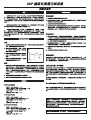
2m
1m
1m
1m
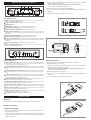
Fig. A
Setup And Connection For Receiver
Setup:
1. For best operation the receiver should be at least 1m above the ground and
at least 1m away from a wall or metal surface to minimize reflections.
2 . K e ep t h e r ec e iv e r ’s a n te n n a s a w a y
fr o m n oi s e so u r ces s uch a s mo t or s,
aut omobiles, digital devices and neon
lights, as well as large metal objects.
3. Position the receiver so that it has the
fewest possible obstructions between it
and the normal location of the wireless
microphone. Line-of-sight is best.
4. When two transmitters are used simulta-
ne o u s ly, ke e p t he t ra n sm it t er s a t l e as t 2 m a wa y f r om t h e r e ce iv er,
meanwhile keep 2m at least between each transmitter.
Connection:
1. There are 2 kinds of audio outputs on the back of the receiver: balanced
(200 mV) and unbalanced (360 mV). Use shielded audio cable for the
connection between the receiver and the mixer. If the input of the mixer
is an XLR-type input, connect cables from the balanced XLR-type audio
outputs on the back of the receiver to the mixer. If the input of the mixer is
a 1/4” jack, connect cables from the 1/4” unbalanced audio outputs on the
back of the receiver to the mixer.
2. Attach the antennas to the antenna connectors on the front of the receiver.
3. Connect the included AC adapter to the DC power input on the back of the
receiver.
CAUTION! Electrical shock can result from removal of the receiver cover. Refer
servicing to qualified service personnel. No user-serviceable parts inside. Do not
expose to rain or moisture.
The circuits insid e the receiv er and tran smitte r have been precisel y adjuste d for
optimum performance and compliance with federal regulations. Do not attempt to open
the receiver or transmitter. To do so will void the warranty, and may cause improper
operation.
Individu als with implante d c ard iac pacemake rs or AI CD de vices:
Please see notice on back cover.
ATW-0814MK3
Receiver: ATW-R08MK3 x 1 pc.
Transmitter: ATW-T14MK3 (hand-held wireless microphone) x 2 pcs.
AC adapter: 12V DC 500mA x 1 pc.
Antennas: 1 pair.
Connection cable: 6.3mm plug x 1 pc.
ATW-0817MK3
Receiver: ATW-R08MK3 x 1 pc.
Transmitter: ATW-T17MK3
(unipak transmitter) x 2 pcs.
AC adapter: 12V DC 500mA x 1 pc.
Antennas: 1 pair.
Connection cable: 6.3mm plug x 1 pc.
ATW-0814/17MK3
Receiver: ATW-R08MK3 x 1 pc.
Transmitter: ATW-T14MK3
(hand-held wireless microphone) x 1 pcs.
ATW-T17MK3
(unipak transmitter) x 1 pcs.
AC adapter: 12V DC 500mA x 1 pc.
Antennas: 1 pair.
Connection cable: 6.3mm plug x 1 pc.

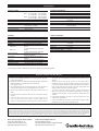
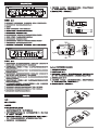
Adjustment And Functions Of Receiver
Front Panel
(Fig. B)
TUNER A ANTENNA CONNECTOR: Antenna connector for tuner “A.” Attach the antenna
directly, or extand it with an antenna cable.
TUNER A AF LEVEL CONTROL: Adjusts the audio output level of tuner “A.”
POWER INDICATOR
POWER SWITCH: Press switch on, and the “POWER” indicator will light.
TUNER A OPERATION INDICATOR: Indicates the signal condition of tuner “A.”
TUNER A CHANNEL CHANGE SWITCH: Switches the channels of tuner “A.”
TUNER A AF PEAK INDICATOR: Indicates when maximum modulation of the microphone A
without distortion has been reached (AF level control adjustment does not affect the maximum
modulation).
TUNER B OPERATION INDICATOR: Indicates the signal condition of tuner “B.”
TUNER B CHANNEL CHANGE SWITCH: Switches the channels of tuner “B.”
TUNER B AF PEAK INDICATOR: Indicates when maximum modulation of the microphone A
without distortion has been reached (AF level control adjustment does not affect the maximum
modulation).
TUNER B AF LEVEL CONTROL: Adjusts the audio output level of tuner “B.”
TUNER B ANTENNA CONNECTOR: Antenna connector for tuner “B.” Attach the antenna
directly, or extand it with an antenna cable.
1
2
3
4
5
7
8
9
10
11
12
Rear Panel
(Fig. C)
TUNER B GROUND LIFT SWITCH: Disconnects the ground pin of the balanced output (14)
of tuner “B” from ground. Normally, the switch should be to the left (ground connected). If hum
caused by a ground loop occurs, slide switch to the right.
TUNER B BALANCED AUDIO OUTPUT JACK: XLRM-type connector of tuner “B.” A standard
2-conductor shielded cable can be used to connect the receiver output to a balanced input on a
mixer.
TUNER A BALANCED AUDIO OUTPUT JACK: XLRM-type connector of tuner “A.” A standard
2-conductor shielded cable can be used to connect the receiver output to a balanced input on a
mixer.
TUNER A GROUND LIFT SWITCH: Disconnects the ground pin of the balanced output (15)
of tuner “A” from ground. Normally, the switch should be to the left (ground connected). If hum
caused by a ground loop occurs, slide switch to the right.
TUNER B UNBALANCED AUDIO OUTPUT JACK: 6.3mm phone jack of tuner “B.” Can be
connected to an unbalanced audio-level input of a mixer or amplier.
TUNER A UNBALANCED AUDIO OUTPUT JACK: 6.3mm phone jack of tuner “A.” Can be
connected to an unbalanced audio-level input of a mixer or amplier.
TUNER A & B MIX UNBALANCED AUDIO OUTPUT JACK: 6.3mm phone jack of mixed audio output of
tuners “A” and “B.” Can be connected to an unbalanced audio-level input of a mixer or amplier.
TUNER B SQUELCH CONTROL: Adjusts level of noise-muting circuit of tuner “B” (preset at
factory, but can be adjusted as circumstances warrant).
TUNER A SQUELCH CONTROL: Adjusts level of noise-muting circuit of tuner “A” (preset at
factory, but can be adjusted as circumstances warrant).
DC POWER INPUT JACK: Always use the included AC adapter.
6
ANT. A ANT. B
MIN MAX
OFF
CH.2CH.1
ON
AF LEVEL
POWER
TUNER A AF PEAK
MIN MAX
AF LEVEL
CH.2CH.1
TUNER B AF PEAK
AT W-R
08MK3
UHF DUAL RECEIVER
Fig. B Receiver Front Panel
5
43
1
12
62
7
8
9
10
11
TUNER B
AF OUT BALANCED
TUNER A
TUNER B MIXTUNER A
TUNER B TUNER A
GROUND
AF OUT UN BALANCED
GROUND LIFT
GROUND
GROUND LIFT
DC 12V 18V
500mA
SOUELCH ADJ.
Fig. C Receiver Rear Panel
191817
1513
20
14
16 21 22
13
14
15
16
17
18
19
20
21
22
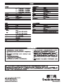
Transmitter Setup
Batteries
AA alkaline batteries are strongly recommended for the best operation.
Battery Installation
Handheld transmitter
1. Make certain that the power switch of microphone (located at side of the
microphone) is turned off.
2. While holding the upper part of the microphone body just below the ball-
screen, unscrew the lower body cover and slide it downward to expose the
battery compartment.
1 2
LR6,AA
LR6,AA
ON
Power Switch
Battery Condition Indicator
Battery Polarity Diagram
Channel Switch
Fig. D
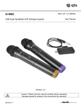
UniPak transmitter
1. Make certain that the power switch of transmitter is turned off.
2. Slide off the battery cover (Fig. F)
3. Carefully insert two fresh AA alkaline batteries, observing correct polarity
as marked inside the battery compartment.
WARNING!! Do not insert the batteries with incorrect polarity. It may
cause a major damage to electronics.
4. Replace the lower body cover.(Fig. G)
5. Turn on switch of the transmitter and check that the battery indicator (red
LED) is on.
6. Turn off switch of the transmitter when not in use.
A
T
W
-
T
17
TR
A
N
SM
IT
T
ER
Fig. F
A
T
W
-
T
17
T
RA
NSM
IT
T
E
R
Fig. G
MT
Lo Hi
GT
Lo
1 2
Hi
ATW
-
T
17
TRANSMITTER
LR6,AA
LR6,AA
INPUT
BATT.
POWER
OFF ON
ANT.
Channel Switch
Screw Driver
Mic Trimmer
Guitar T rimmer
Power Switch
Battery Indicator
Antenna
Input Connector
Fig. E
3. Insert two fresh AA alkaline batteries. Observe correct polarity as marked
inside the battery compartment.
WARNING!! Do not insert the batteries with incorrect polarity.
It may cause a major damage to electronics.
4. Replace the lower body cover. Do not overtighten.
5. Turn on switch of the microphone and check that the battery indicator (red
LED) is on.
6. Turn off switch of the microphone when not in use.

Specications
OVERALL SYSTEM
Operating Frequency UHF 2 band
No.1 A1 ch 739.750 MHz, A2 ch 740.500 MHz
B1 ch 733.875 MHz, B2 ch 734.375 MHz
No.2 A1 ch 819.025 MHz, A2 ch 819.575 MHz
B1 ch 811.100 MHz, B2 ch 811.575 MHz
Frequency Stability ±0.005%, Crystal-controlled
Modulation Mode FM
Maximum Deviation Range ±10 kHz
Operation Range about 100m
(Under optimum condition)
Operation Temperature Range 4º C to 45º C
Frequency Response 100 Hz to 10 kHz
HANDHELD TRANSMITTER
Polar Pattern Unidirectional
RF Power Output * 20mW norminal
Spurious Emission * ETS 300 422
Microphone Element Dynamic Capsule
Battery 1.5V Type AA (LR6) alkaline X 2,
not included
Current Consumption 220 mA typical
Battery Life 6 ~ 8 hours
Dimensions 245.0 mm long,
38.0 mm body dia.
Net Weight (Without Battery) 215 grams
UNIPAK TRANSMITTER
RF Power Output * 20mW typ.
Spurious Emission * ETS 300 422
Input Connection High impedance, low impedance, bias
Battery 1.5V Type AA (LR6) alkaline X 2,
not included
Current Consumption 220 mA typical
Battery Life 6 ~ 8 hours
Dimensions 65.0 mm W x 110.0 mm H x 25.4 mm D
Net Weight (Without Battery) 95 grams
RECEIVER
Receiving System Dual independent receivers
Image Rejection ≥ 40 dB
Signal-to-noise Ratio * > 80 dB
Total Harmonic Distortion ≤ 1%
Sensitivity 10 µV for 60 dB S/N (IEC weighted)
Audio Output
Unbalanced: 360 mV
(at 1kHz,±10kHz deviation, 10kΩ load)
Balanced: 200 mV
(at 1kHz,±10kHz deviation, 10kΩ load)
Output Connectors
Unbalanced: 6.3mm phone jack
Balanced: XLRM-type
Power Supply 12-18V DC, 500 mA, with provided AC
adapter
Dimensions 210.0 mm W x 49.0 mm H x 251 mm D
Weight 1.34 kgs
Accessories Included Two whip anntenas (can be bended)
* Carrier frequency, maximum deviation and output power depends on government regulations.
Notice to individuals with implanted cardiac pacemakers or AICD devicers:
Any source to RF (ratio frequency) energy may interfere with normal functioning of the implanted device. All wireless microphones have low-power transmitters (less than 0.05 watts output)
which are unlikely to cause difculty, especially if they are at least a few inches away. However, since a “body-pack” mic transmitter typically is placed against the body, we suggeat attaching
it at the belt, rather than in a shirt pocket where it may be immediately adjacent to the medical device. Note also that any medical-device disruption will cease when the RF transmitting
source is turned off. Please contact your physician or medical-device provider if you have any questions, or experience any problems with the use of this or any other RF equipment.
Audio Technica (Greater China) Limited
Unit K, 9/F., Kaiser Est. (Ph. 2),
51 Man Yue Street, Kowloon, HK.
http://www.audio-technica.com.hk
Nine Tips To Obtain The Best Results
1. Use only fresh alkaline batteries. Do not use “general purpose”
(carbon-zinc) batteries.
2. Position the receiver so that it has the fewest possible obstructions
between it and the normal location of the transmitter.
Line-of-sight is best.
3. The transmitter and the receiver should be as close together as
conveniently possible, but no closer together than one meter.
4. The receiver antennas should be in the open and away from any
metal.
5. The transmitter and receiver must be set to the same channel
number.
6. If the AF Lev el control of the receiver is set too high, it m ay
o v er - d r iv e t h e i n p ut of t h e m ix er o r c l ip th e o u t pu t o f t h e
receiver, causing distortion. Conversely, if the receiver output is
set too low, the overall signal-to-noise ratio of the system may be
reduced.
Ad j u s t the o u t p u t level of th e receiver s o th e highest s o u n d
pressure level going into the microphone causes no input overload
in the mixer, and yet permits the mixer level controls to operate in
their “normal“ range (not set too high or too low). This provides the
optimum signal-to-noise for the entire system.
7. You n e ed t o c h ange ch anne ls 1 ) when a s tron g inter f eren ce
signal is received, 2) when the channel breaks down, or 3) during
multiple-system operation in order to select an interference-free
channel.
8. In the UniPak transmitter, the “MT“ or “GT“ input control not in use
should be set to minimum.
9. Turn the transmitter off when not in use. Remove the battery if the
transmitter is not to be used for a period of time.
Audio-Technica (S.E.A.) Pte. Ltd.
623 Aljunied Road, #04-10,
Aljunied Industrial Complex, Singapore 389835
http://www.audio-technica.com.sg
Form No. ATGC-WM-002-03


-
 1
1
-
 2
2
-
 3
3
-
 4
4
-
 5
5
-
 6
6
-
 7
7
-
 8
8


Audio Technica ATW-0814 User manual
- Category
- Guitar accessories
- Type
- User manual
- This manual is also suitable for
Ask a question and I''ll find the answer in the document
Finding information in a document is now easier with AI
Related papers
-
Audio Technica ATW-1951 Operating instructions
-
Audio Technica ATW-7375 Operating instructions
-
-
-
-
Audio-Technica ATW-1663 User manual
-
-
-
AmpliVox ATW-701L User manual
-
Audio-Technica ATW-701/H User manual
Other documents
-
-
 Avsl QTX U-MIC User manual
-
 RSQ UHF-438 Operating instructions
-
Vonyx 141148 Operating instructions
-
Pyle PDWMU105 Owner's manual
-
 Califone R-2000 User manual
-
Anchor UHF-6400 Owner's manual
-
-
-


