Supermicro SUPERSERVER 6013A-T User manual
- Category
- Server barebones
- Type
- User manual

®
SUPER
SUPERSERVER 6013A-T
USER’S MANUAL
Revision 1.1b

The information in this User’s Manual has been carefully reviewed and is believed to be
accurate. The vendor assumes no responsibility for any inaccuracies that may be
contained in this document, makes no commitment to update or to keep current the
information in this manual, or to notify any person or organization of the updates.
Please
Note: For the most up-to-date version of this manual, please see our
web site at www.supermicro.com.
SUPERMICRO COMPUTER reserves the right to make changes to the product described in
this manual at any time and without notice. This product, including software, if any, and
documentation may not, in whole or in part, be copied, photocopied, reproduced, translated
or reduced to any medium or machine without prior written consent.
IN NO EVENT WILL SUPERMICRO COMPUTER BE LIABLE FOR DIRECT, INDIRECT,
SPECIAL, INCIDENTAL, SPECULATIVE OR CONSEQUENTIAL DAMAGES ARISING FROM
THE USE OR INABILITY TO USE THIS PRODUCT OR DOCUMENTATION, EVEN IF
ADVISED OF THE POSSIBILITY OF SUCH DAMAGES. IN PARTICULAR, THE VENDOR
SHALL NOT HAVE LIABILITY FOR ANY HARDWARE, SOFTWARE, OR DATA STORED
OR USED WITH THE PRODUCT, INCLUDING THE COSTS OF REPAIRING, REPLACING,
INTEGRATING, INSTALLING OR RECOVERING SUCH HARDWARE, SOFTWARE, OR
DATA.
Any disputes arising between manufacturer and customer shall be governed by the laws of
Santa Clara County in the State of California, USA. The State of California, County of
Santa Clara shall be the exclusive venue for the resolution of any such disputes.
Supermicro's total liability for all claims will not exceed the price paid for the hardware
product.
Unless you request and receive written permission from SUPER MICRO COMPUTER, you
may not copy any part of this document.
Information in this document is subject to change without notice. Other products and
companies referred to herein are trademarks or registered trademarks of their respective
companies or mark holders.
Copyright © 2005 by SUPER MICRO COMPUTER INC.
All rights reserved.
Printed in the United States of America

Preface
About This Manual
This manual is written for professional system integrators and PC technicians.
It provides information for the installation and use of the SuperServer 6013A-T.
Installation and maintainance should be performed by experienced technicians
only.
The SuperServer 6013A-T is an affordable dual Xeon processor 1U rackmount
server based on the SC811T-350 chassis and the Super X5DPA-TGM+
motherboard. The X5DPA-TGM+ supports dual Intel® Xeon
TM
processors of up to
3.20 GHz with a 1 MB cache.
Manual Organization
Chapter 1: Introduction
The first chapter provides a checklist of the main components included with the
server system and describes the main features of the Super X5DPA-TGM+
motherboard and the SC811T-350 chassis.
Chapter 2: Server Installation
This chapter describes the steps necessary to install the SuperServer
6013A-T into a rack and check out the server configuration prior to power-
ing up the system. If your server was ordered without the processor and
memory components, this chapter will refer you to the appropriate sections
of the manual for their installation.
Chapter 3: System Interface
Refer to this chapter for details on the system interface, which includes the
functions and information provided by the control panel on the chassis as
well as other LEDs located throughout the system.
iii
Preface

SUPERSERVER 6013A-T User's Manual
iv
Chapter 4: System Safety
You should thoroughly familiarize yourself with this chapter for a general
overview of safety precautions that should be followed when installing and
servicing the SuperServer 6013A-T.
Chapter 5: Advanced Motherboard Setup
Chapter 5 provides detailed information on the X5DPA-TGM+ motherboard, in-
cluding the locations and functions of connectors, headers and jumpers. Refer
to this chapter when adding or removing processors or main memory and when
reconfiguring the motherboard.
Chapter 6: Advanced Chassis Setup
Refer to Chapter 6 for detailed information on the SC811T-350 1U rackmount
server chassis. You should follow the procedures given in this chapter
when installing, removing or reconfiguring Serial ATA or peripheral drives
and when replacing system power supply units and cooling fans.
Chapter 7: AMIBIOS
The BIOS chapter includes an introduction to BIOS and provides detailed
information on running the CMOS Setup Utility.
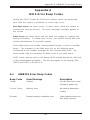
Appendix A: BIOS Error Beep Codes
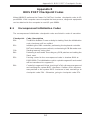
Appendix B: BIOS POST Checkpoint Codes
Appendix C: Software Installation
Appendix D: System Specifications

v
Preface
Notes

vi
Table of Contents
Preface
About This Manual ...................................................................................................... iii
Manual Organization ................................................................................................... iii
Chapter 1: Introduction
1-1 Overview......................................................................................................... 1-1
1-2 Motherboard Features ................................................................................... 1-2
1-3 Server Chassis Features.............................................................................. 1-5
1-4 Contacting Supermicro .................................................................................. 1-7
Chapter 2: Server Installation
2-1 Overview......................................................................................................... 2-1
2-2 Unpacking the SuperServer 6013A-T ........................................................ 2-1
2-3 Preparing for Setup ....................................................................................... 2-1
Choosing a Setup Location.................................................................... 2-2
Rack Precautions ..................................................................................... 2-2
Server Precautions.................................................................................. 2-2
Rack Mounting Considerations .............................................................. 2-3
2-4 Installing the SuperServer 6013A-T into a Rack ...................................... 2-4
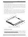
Identifying the Sections of the Rack Rails.......................................... 2-4
Installing the Chassis Rails ..................................................................... 2-5
Installing the Rack Rails .......................................................................... 2-5
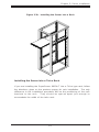
Installing the Server into the Rack ........................................................ 2-6
Installing the Server into a Telco Rack ................................................ 2-7
2-5 Checking the Motherboard Setup ................................................................ 2-9
2-6 Checking the Drive Bay Setup................................................................... 2-11
Chapter 3: System Interface
3-1 Overview......................................................................................................... 3-1
3-2 Control Panel Buttons .................................................................................... 3-1
Reset.......................................................................................................... 3-1
Power ........................................................................................................ 3-1
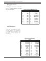
3-3 Control Panel LEDs ........................................................................................ 3-2
Overheat ................................................................................................... 3-2
NIC2 ............................................................................................................ 3-2
NIC1 ............................................................................................................ 3-2
HDD ............................................................................................................ 3-2
Power ........................................................................................................ 3-3
SUPERSERVER 6013A-T User's Manual

3-4 Serial ATA Drive Carrier LED ...................................................................... 3-3
Chapter 4: System Safety
4-1 Electrical Safety Precautions ........................................................................ 4-1
4-2 General Safety Precautions .......................................................................... 4-2
4-3 ESD Precautions .............................................................................................. 4-3
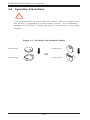
4-4 Operating Precautions .................................................................................... 4-4
Chapter 5: Advanced Motherboard Setup
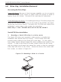
5-1 Handling the X5DPA-TGM+ Motherboard........................................................5-1
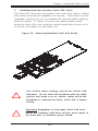
5-2 Motherboard Installation....................................................................................5-2
5-3 Connecting Cables ............................................................................................5-3
Connecting Data Cables ............................................................................5-3
Connecting Power Cables ..........................................................................5-3
Connecting the Control Panel ...................................................................5-3
5-4 I/O Ports .............................................................................................................5-4
5-5 Processor and Heatsink Installation ...............................................................5-5
5-6 Installing Memory ..............................................................................................5-9
5-7 Adding PCI Cards ............................................................................................5-10
5-8 Motherboard Details ........................................................................................5-11
X5DPA-TGM+ Layout................................................................................5-11
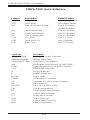
X5DPA-TGM+ Quick Reference...............................................................5-12
5-9 Connector Definitions ......................................................................................5-13
ATX Power Connection ........................................................................... 5-13
PWR_SEC Connection .............................................................................5-13
Power LED.................................................................................................5-13
NMI Button.................................................................................................5-13
HDD LED ...................................................................................................5-14
NIC1 LED ...................................................................................................5-14
NIC2 LED ...................................................................................................5-14
Overheat LED (OH) ................................................................................. 5-14
Power Fail LED .........................................................................................5-14
Reset Button .............................................................................................5-15
Power Button.............................................................................................5-15
Chassis Intrusion ......................................................................................5-15
Universal Serial Bus (USB0/1) ................................................................5-15
Front Side USB.........................................................................................5-16
Serial Ports ............................................................................................. 5-16
Ethernet Ports ......................................................................................... 5-16
vii
Table of Contents

viii
Fan Headers............................................................................................ 5-17
Power LED/Speaker ............................................................................... 5-17
ATX PS/2 Keyboard and PS/2 Mouse Ports ...................................... 5-17
SMBus Header ........................................................................................5-18
Wake-On-Ring ......................................................................................... 5-18
Keylock .................................................................................................... 5-18
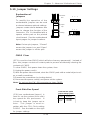
5-10 Jumper Settings............................................................................................. 5-19
Explanation of Jumpers .........................................................................5-19
CMOS Clear.............................................................................................. 5-19
Front Side Bus Speed ........................................................................... 5-19
GLAN/LAN Enable/Disable..................................................................... 5-20
VGA Enable/Disable ............................................................................... 5-20
Watch Dog Enable/Disable ....................................................................5-20
5-11 Onboard Indicators ....................................................................................... 5-20
GLAN/LAN LEDs ..................................................................................... 5-20
5-12 Parallel Port, Floppy and Hard Drive Connections .................................. 5-21
Parallel Port .............................................................................................. 5-21
Floppy Connector................................................................................... 5-22
IDE Connectors ...................................................................................... 5-22
Chapter 6: Advanced Chassis Setup
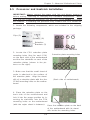
6-1 Static-Sensitive Devices ................................................................................ 6-1
6-2 Control Panel .................................................................................................... 6-2
6-3 System Fans .................................................................................................... 6-3
System Fan Failure.................................................................................. 6-3
Replacing System Cooling Fans............................................................ 6-3
6-4 Drive Bay Installation/Removal ...................................................................... 6-4
Accessing the Drive Bays ..................................................................... 6-4
Serial ATA Drive Installation.................................................................. 6-4
CD-ROM and Floppy Drive Installation ................................................. 6-6
6-5 Power Supply .................................................................................................. 6-7
Power Supply Failure ............................................................................. 6-7
Replacing the Power Supply ................................................................. 6-7
Chapter 7: AMIBIOS
7-1 Introduction....................................................................................................... 7-1
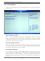
7-2 Main Setup........................................................................................................ 7-2
7-3 Advanced BIOS Setup.................................................................................... 7-5
7-4 Boot Settings.................................................................................................. 7-19
7-5 Security Settings........................................................................................... 7-21
SUPERSERVER 6013A-T User's Manual

Table of Contents
ix
7-6 Exit Options ....................................................................................................7-22
Appendices:
Appendix A: BIOS Error Beep Codes .................................................................. A-1
Appendix B: BIOS POST Checkpoint Codes.........................................................B-1
Appendix C: Software Installation .........................................................................C-1
Appendix D: System Specifications ......................................................................D-1

x
Notes
SUPERSERVER 6013A-T User's Manual

Chapter 1
Introduction
1-1 Overview
The Supermicro SuperServer 6013A-T is an economical dual Xeon processor, 1U
rackmount server with state-of-the-art features. The 6013A-T is comprised of two
main subsystems: the SC811T-350 chassis and the X5DPA-TGM+ motherboard.
Please refer to our web site for information on operating systems that have been
certified for use with the 6013A-T (www.supermicro.com).
In addition to the motherboard and chassis, various hardware components may
have been included with your SuperServer 6013A-T, as listed below.
z Two (2) 1U CPU heatsinks (SNK-039)
z Four (4) heatsink retention clips (for either 604 or 603-pin CPUs)
z Two (2) CPU mounting plates and retention modules (SKT-120)
z One (1) 3.5" floppy drive
z One (1) slim CD-ROM drive
z Serial ATA (SATA) Accessories:
One (1) SATA backplane (CSE-SATA-810)
Two (2) SATA cables (CBL-0058)
One (1) SATA LED cable (CBL-0056)
Two (2) SATA drive carriers (CSE-PT10)
z One (1) 5V 32-bit, 33 MHz PCI slot riser card (CSE-RR32-1U)
z Rackmount hardware (with screws):
Two (2) rack rail assemblies
Six (6) brackets for mounting the rack rails in a rack/telco rack
z One (1) CD containing drivers and utilities
Chapter 1: Introduction
1-1

1-2
SUPERSERVER 6013A-T User's Manual
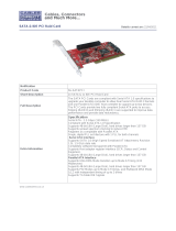
1-2 Motherboard Features
At the heart of the SuperServer 6013A-T lies the X5DPA-TGM+, a dual processor
motherboard designed to provide maximum performance. Below are the main
features of the X5DPA-TGM+. See Figure 1-1 for a system block diagram of the
chipset.
Chipset Overview
Intel’s E7501 chipset is made up of two main components:
The Memory Controller Hub (MCH)
The I/O Controller Hub (ICH5R)
Memory Controller Hub (MCH)
The MCH has four hub interfaces, one to communicate with the ICH5R and three
for high-speed I/O communications. The MCH employs a 144-bit wide memory
bus for a DDR-266 memory interface, which provides a total bandwidth of 3.2 GB/
s. The ICH5R interface is a 266 MB/sec point-to-point connection using an 8-
bit wide, 66 MHz base clock at a 4x data transfer rate. The P64H2 interface is
a 1 GB/s point-to-point connection using a 16-bit wide, 66 MHz base clock at a
8x data transfer rate.
I/O Controller Hub (ICH5R)
The I/O Controller Hub (Intel's ICH5R) provides the I/O subsystem with access
to the rest of the system. It supports 2-channel Ultra ATA/100 Bus Master IDE
Controller, two Serial ATA (SATA) Host Controllers, SMBus 2.0 Controller, LPC/
Flash BIOS Interface, PCI 2.3 Interface, and Integrated System Management
Controller.
Processors
The X5DPA-TGM+ supports dual Intel® Xeon
TM
processors of up to 3.20 GHz with
a 1 MB cache. Please refer to the support section of our web site for a complete
listing of supported processors: (http://www.supermicro.com/
TechSupport.htm).

Chapter 1: Introduction
1-3
Memory
The X5DPA-TGM+ has four (4) 184-pin DIMM sockets that can support up to 8
GB of registered ECC DDR-266/200 SDRAM modules. Low-profile memory
modules are required for use in the 1U form factor of the 6013A-T. Module sizes
of 128 MB, 256 MB, 512 MB and 2 GB may be used to populate the DIMM slots.
(The X5DPA-TGM+ was designed to support 2 GB DIMM modules in each memory
slot, but it has only been validated with 1 GB memory modules.)
Serial ATA
The ICH5R hub supports a two-port Serial ATA subsystem, which is RAID 0 and
RAID 1 supported. The Serial ATA drives are hot-swappable units.
Note: The operating system you use must have RAID support to enable the hot-
swap capability and RAID function of the Serial ATA drives.
PCI Expansion Slots
The X5DPA-TGM+ has five 32-bit, 33 MHz PCI slots, one of which is available in
the 6013A-T 1U configuration. One riser card is included with the system for use
with a 32-bit PCI card.
Ethernet Ports
The X5DPA-TGM+ features Intel's 82541 and 82550 Ethernet controllers, which
support one Gb LAN port and one 10/100 Mb LAN port, respectively.
Onboard Controllers/Ports
An onboard IDE controller supports one floppy drive and up to four* Ultra ATA 100
hard drives or ATAPI devices. Onboard I/O backpanel ports include one COM
port, a VGA port, two USB ports, PS/2 mouse and keyboard ports, a Gb LAN and
a Mb LAN port. (*Only two IDE drives can be housed in the chassis.)
Other Features
Other onboard features that promote system health include eight voltage moni-
tors, a chassis intrusion header, auto-switching voltage regulators, chassis and
CPU overheat sensors, virus protection and BIOS rescue.

1-4
SUPERSERVER 6013A-T User's Manual
MCH
533/400 M H z System B us
2 6 6 M H z M e m o ry B u s
ATA 100
P o rts
Processor 1 P rocessor2
2-C hannel
DDR SDRAM
IC H 5 R
U S B P o rts
GLAN
LAN
ATI Rage
32-bit P C I # 1
33 M H z P C I B u s
32-bit P C I # 3
32-bit P C I # 2
32-bit P C I # 4
32-bit P C I # 5
LPC I/O
C O M P o rts
H/W
M onito r
Floppy
Kybd/
M ouse
SATA
Figure 1-1. Intel E7501 Chipset:
System Block Diagram
Note: This is a general block diagram. Please see Chapter 5 for details.

Chapter 1: Introduction
1-5
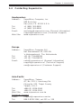
1-3 Server Chassis Features
The SuperServer 6013A-T is a 1U rackmount server platform designed with some
of today's most state-of-the-art features. The following is a general outline of the
main features of the SC811T-350 chassis.
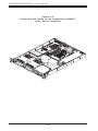
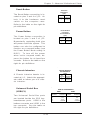
System Power
When configured as a SuperServer 6013A-T, the SC811T-350 chassis includes
a single 350W power supply.
Serial ATA Subsystem
For the 6013A-T, the SC811T-350 chassis was designed to support two
Serial ATA hard drives. The Serial ATA drives are hot-swappable units.
(ATA/100 IDE drives are also supported.)
Note: The operating system you use must have RAID support to enable the
hot-swap capability of the Serial ATA drives.
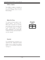
Control Panel
The control panel on the SC811T-350 provides important system monitoring
and control information. LEDs indicate power on, network activity, hard
disk drive activity and system overheat conditions. The control panel also
includes a main power button and a system reset button.
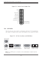
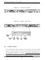
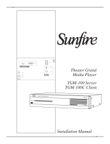
Rear I/O Panel
The SC811T-350 is a 1U rackmount chassis. Its I/O panel provides one
motherboard expansion slot, one COM port (another is internal), two USB
ports, PS/2 mouse and keyboard ports, a graphics port and two Ethernet
ports (see Figure 1-2).

1-6
SUPERSERVER 6013A-T User's Manual
Cooling System
The SC811T-350 chassis has an innovative cooling design that includes two 10-
cm blower fans for system cooling located in the midsection of the chassis. The
blower fans plug into chassis fan headers on the motherboard and operate at full
rpm continuously. If either break down, the ambient air temperature inside the
chassis will rise and activate an overheat LED.
Figure 1-2. Rear I/O Panel

Chapter 1: Introduction
1-7
1-4 Contacting Supermicro
Headquarters
Address: SuperMicro Computer, Inc.
980 Rock Ave.
San Jose, CA 95131 U.S.A.
Tel: +1 (408) 503-8000
Fax: +1 (408) 503-8008
Email: [email protected] (General Information)
[email protected] (Technical Support)
Web Site: www.supermicro.com
Europe
Address: SuperMicro Computer B.V.
Het Sterrenbeeld 28, 5215 ML
's-Hertogenbosch, The Netherlands
Tel: +31 (0) 73-6400390
Fax: +31 (0) 73-6416525
Email: [email protected] (General Information)
[email protected] (Technical Support)
[email protected] (Customer Support)
Asia-Pacific
Address: SuperMicro, Taiwan
4F, No. 232-1, Liancheng Rd.
Chung-Ho 235, Taipei County
Taiwan, R.O.C.
Tel: +886-(2) 8226-3990
Fax: +886-(2) 8226-3991
Web Site: www.supermicro.com.tw
Technical Support:
Email: su[email protected]
Tel: 886-2-8228-1366, ext.132 or 139

1-8
SUPERSERVER 6013A-T User's Manual
Notes

Chapter 2: Server Installation
2-1
Chapter 2
Server Installation
2-1 Overview
This chapter provides a quick setup checklist to get your SuperServer
6013A-T up and running. Following the steps in the order given should
enable you to have the system operational within a minimal amount of time.
This quick setup assumes that your 6013A-T system has come to you with
the processor and memory preinstalled. If your system is not already fully
integrated with a motherboard, processor, system memory etc., please turn
to the chapter or section noted in each step for details on installing specific
components.
2-2 Unpacking the SuperServer 6013A-T
You should inspect the box the SuperServer 6013A-T was shipped in and
note if it was damaged in any way. If the server itself shows damage, you
should file a damage claim with the carrier who delivered it.
Decide on a suitable location for the rack unit that will hold the SuperServer
6013A-T. It should be situated in a clean, dust-free area that is well venti-
lated. Avoid areas where heat, electrical noise and electromagnetic fields
are generated. You will also need it placed near a grounded power outlet.
Read the Rack and Server Precautions in the next section.
2-3 Preparing for Setup
The box the SuperServer 6013A-T was shipped in should include two sets
of rail assemblies, two rail mounting brackets and the mounting screws you
will need to install the system into the rack. Follow the steps in the order
given to complete the installation process in a minimal amount of time.
Please read this section in its entirety before you begin the installation
procedure outlined in the sections that follow.

2-2
SUPERSERVER 6013A-T User's Manual
Choosing a Setup Location
- Leave enough clearance in front of the rack to enable you to open
the front door completely (~25 inches).
- Leave approximately 30 inches of clearance in the back of the rack
to allow for sufficient airflow and ease in servicing.
- This product is for installation only in a Restricted Access Location
(dedicated equipment rooms, service closets, etc.).
Rack Precautions
- Ensure that the leveling jacks on the bottom of the rack are fully
extended to the floor with the full weight of the rack resting on them.
- In a single rack installation, stabilizers should be attached to the rack.
- In multiple rack installations, the racks should be coupled together.
- Always make sure the rack is stable before extending a component
from the rack.
- You should extend only one component at a time - extending two or
more simultaneously may cause the rack to become unstable.
Server Precautions
- Review the electrical and general safety precautions in Chapter 4.
- Determine the placement of each component in the rack before you
install the rails.
- Install the heaviest server components on the bottom of the rack
first, and then work up.
- Use a regulating uninterruptible power supply (UPS) to protect the
server from power surges, voltage spikes and to keep your
system operating in case of a power failure.
- Allow the power supply units and hot plug Serial ATA drives to
cool before touching them.
- Always keep the rack's front door and all panels and components on
the servers closed when not servicing to maintain proper cooling.
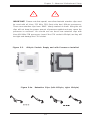
!
!
Warnings and Precautions!
Page is loading ...
Page is loading ...
Page is loading ...
Page is loading ...
Page is loading ...
Page is loading ...
Page is loading ...
Page is loading ...
Page is loading ...
Page is loading ...
Page is loading ...
Page is loading ...
Page is loading ...
Page is loading ...
Page is loading ...
Page is loading ...
Page is loading ...
Page is loading ...
Page is loading ...
Page is loading ...
Page is loading ...
Page is loading ...
Page is loading ...
Page is loading ...
Page is loading ...
Page is loading ...
Page is loading ...
Page is loading ...
Page is loading ...
Page is loading ...
Page is loading ...
Page is loading ...
Page is loading ...
Page is loading ...
Page is loading ...
Page is loading ...
Page is loading ...
Page is loading ...
Page is loading ...
Page is loading ...
Page is loading ...
Page is loading ...
Page is loading ...
Page is loading ...
Page is loading ...
Page is loading ...
Page is loading ...
Page is loading ...
Page is loading ...
Page is loading ...
Page is loading ...
Page is loading ...
Page is loading ...
Page is loading ...
Page is loading ...
Page is loading ...
Page is loading ...
Page is loading ...
Page is loading ...
Page is loading ...
Page is loading ...
Page is loading ...
Page is loading ...
Page is loading ...
Page is loading ...
Page is loading ...
Page is loading ...
Page is loading ...
Page is loading ...
Page is loading ...
Page is loading ...
Page is loading ...
Page is loading ...
Page is loading ...
Page is loading ...
Page is loading ...
Page is loading ...
Page is loading ...
Page is loading ...
Page is loading ...
Page is loading ...
Page is loading ...
Page is loading ...
Page is loading ...
Page is loading ...
Page is loading ...
Page is loading ...
Page is loading ...
Page is loading ...
Page is loading ...
Page is loading ...
Page is loading ...
Page is loading ...
Page is loading ...
Page is loading ...
Page is loading ...
Page is loading ...
Page is loading ...
Page is loading ...
Page is loading ...
Page is loading ...
Page is loading ...
Page is loading ...
Page is loading ...
Page is loading ...
Page is loading ...
-
 1
1
-
 2
2
-
 3
3
-
 4
4
-
 5
5
-
 6
6
-
 7
7
-
 8
8
-
 9
9
-
 10
10
-
 11
11
-
 12
12
-
 13
13
-
 14
14
-
 15
15
-
 16
16
-
 17
17
-
 18
18
-
 19
19
-
 20
20
-
 21
21
-
 22
22
-
 23
23
-
 24
24
-
 25
25
-
 26
26
-
 27
27
-
 28
28
-
 29
29
-
 30
30
-
 31
31
-
 32
32
-
 33
33
-
 34
34
-
 35
35
-
 36
36
-
 37
37
-
 38
38
-
 39
39
-
 40
40
-
 41
41
-
 42
42
-
 43
43
-
 44
44
-
 45
45
-
 46
46
-
 47
47
-
 48
48
-
 49
49
-
 50
50
-
 51
51
-
 52
52
-
 53
53
-
 54
54
-
 55
55
-
 56
56
-
 57
57
-
 58
58
-
 59
59
-
 60
60
-
 61
61
-
 62
62
-
 63
63
-
 64
64
-
 65
65
-
 66
66
-
 67
67
-
 68
68
-
 69
69
-
 70
70
-
 71
71
-
 72
72
-
 73
73
-
 74
74
-
 75
75
-
 76
76
-
 77
77
-
 78
78
-
 79
79
-
 80
80
-
 81
81
-
 82
82
-
 83
83
-
 84
84
-
 85
85
-
 86
86
-
 87
87
-
 88
88
-
 89
89
-
 90
90
-
 91
91
-
 92
92
-
 93
93
-
 94
94
-
 95
95
-
 96
96
-
 97
97
-
 98
98
-
 99
99
-
 100
100
-
 101
101
-
 102
102
-
 103
103
-
 104
104
-
 105
105
-
 106
106
-
 107
107
-
 108
108
-
 109
109
-
 110
110
-
 111
111
-
 112
112
-
 113
113
-
 114
114
-
 115
115
-
 116
116
-
 117
117
-
 118
118
-
 119
119
-
 120
120
-
 121
121
-
 122
122
-
 123
123
-
 124
124
-
 125
125
-
 126
126


Supermicro SUPERSERVER 6013A-T User manual
- Category
- Server barebones
- Type
- User manual
Ask a question and I''ll find the answer in the document
Finding information in a document is now easier with AI
Related papers
-
Supermicro MCP-290-00060-0N Datasheet
-
-
-
Supermicro SuperServer 6021i, Beige User manual
-
-
-
-
-
-
Other documents
-
Sony DDU1681S User manual
-
Gigabyte ICH5R Owner's manual
-
 Cables Direct NL-SATAPCI Datasheet
-
Asus V-Series P5G965 User manual
-
HP 6-Port SATA RAID User manual
-
American Megatrends AMIBIOS8 EZ-Port User guide
-
-
Sitecom CN-806 Datasheet
-
 Sunfire MP3 Player TGM-100 User manual
-
Intel SE7501CW2 - E7501 DUAL PGA604 XEON 533MHZ User manual

