Page is loading ...

MODEL T27621
PROFESSIONAL ENGLISH WHEEL
OWNER'S MANUAL
(For models manufactured since 02/16)
COPYRIGHT © MAY, 2016 BY GRIZZLY INDUSTRIAL, INC.
WARNING: NO PORTION OF THIS MANUAL MAY BE REPRODUCED IN ANY SHAPE
OR FORM WITHOUT THE WRITTEN APPROVAL OF GRIZZLY INDUSTRIAL, INC.
#BL18156 PRINTED IN CHINA
V1.05.16

This manual provides critical safety instructions on the proper setup,
operation, maintenance, and service of this machine/tool. Save this
document, refer to it often, and use it to instruct other operators.
Failure to read, understand and follow the instructions in this manual
may result in fire or serious personal injury—including amputation,
electrocution, or death.
The owner of this machine/tool is solely responsible for its safe use.
This responsibility includes but is not limited to proper installation in
a safe environment, personnel training and usage authorization,
proper inspection and maintenance, manual availability and compre-
hension, application of safety devices, cutting/sanding/grinding tool
integrity, and the usage of personal protective equipment.
The manufacturer will not be held liable for injury or property damage
from negligence, improper training, machine modifications or misuse.
Some dust created by power sanding, sawing, grinding, drilling, and
other construction activities contains chemicals known to the State
of California to cause cancer, birth defects or other reproductive
harm. Some examples of these chemicals are:
• Lead from lead-based paints.
• Crystalline silica from bricks, cement and other masonry products.
• Arsenic and chromium from chemically-treated lumber.
Your risk from these exposures varies, depending on how often you
do this type of work. To reduce your exposure to these chemicals:
Work in a well ventilated area, and work with approved safety equip-
ment, such as those dust masks that are specially designed to filter
out microscopic particles.

INTRODUCTION ............................................................................................................................... 2
Contact Info ................................................................................................................................ 2
Manual Accuracy ........................................................................................................................ 2
Identification ............................................................................................................................... 3
Machine Data Sheet ................................................................................................................... 4
SECTION 1: SAFETY ....................................................................................................................... 5
Safety Instructions for Machinery ............................................................................................... 5
Additional Safety for English Wheels ......................................................................................... 7
SECTION 2: SETUP ......................................................................................................................... 8
Needed for Setup ....................................................................................................................... 8
Unpacking .................................................................................................................................. 8
Inventory ..................................................................................................................................... 9
Cleanup .................................................................................................................................... 10
Site Considerations .................................................................................................................. 11
Assembly .................................................................................................................................. 12
Anchoring to Floor .................................................................................................................... 13
SECTION 3: OPERATIONS ........................................................................................................... 14
Operation Overview.................................................................................................................. 14
Tracking Tips ............................................................................................................................ 15
Replacing Wheels .................................................................................................................... 16
Rotating Wheels ....................................................................................................................... 17
Adjusting Quick-Release Lever ................................................................................................ 18
Selecting Lower Wheels ........................................................................................................... 19
Tracking Patterns ..................................................................................................................... 20
SECTION 4: ACCESSORIES ......................................................................................................... 24
SECTION 5: MAINTENANCE......................................................................................................... 25
Schedule .................................................................................................................................. 25
Cleaning & Protecting .............................................................................................................. 25
Lubrication ................................................................................................................................ 25
SECTION 6: SERVICE ................................................................................................................... 27
Troubleshooting ........................................................................................................................ 27
SECTION 7: PARTS ....................................................................................................................... 28
Main Breakdown....................................................................................................................... 28
Labels & Cosmetics Parts List ................................................................................................. 30
WARRANTY & RETURNS ............................................................................................................. 33
Table of Contents

-2-
Model T27621 (Mfd. Since 2/16)
We stand behind our machines! If you have ques-
tions or need help, contact us with the information
below. Before contacting, make sure you get the
serial number
and manufacture date from the
machine ID label. This will help us help you faster.
Grizzly Technical Support
1815 W. Battlefield
Springfield, MO 65807
Phone: (570) 546-9663
Email: [email protected]
We want your feedback on this manual. What did
you like about it? Where could it be improved?
Please take a few minutes to give us feedback.
Grizzly Documentation Manager
P.O. Box 2069
Bellingham, WA 98227-2069
Email: [email protected]
Contact Info
We are proud to provide a high-quality owner’s
manual with your new machine!
We
made every effort to be exact with the
instruc-
tions, specifications, drawings, and photographs
in this manual. Sometimes we make mistakes, but
our policy of continuous improvement also means
that
sometimes the machine
you receive is
slightly different than shown in the manual
.
If you find this to be the case, and the difference
between the manual and machine leaves you
confused or unsure about something
,
check our
website for an updated version. W
e post
current
manuals and
manual updates for free
on our web-
site at
www.grizzly.com.
Alternatively, you can call our Technical Support
for help. Before calling, make sure you write down
the
Manufacture Date and Serial Number
from
the machine ID label (see below). This information
is required for us to provide proper tech support,
and it helps us determine if updated documenta-
tion is available for your machine.
Manufacture Date
Serial Number
Manual Accuracy
INTRODUCTION

Model T27621 (Mfd. Since 2/16)
-3-
Identification
To reduce your risk of
serious injury, read this
entire manual BEFORE
using machine.
Become familiar with the names and locations of the controls and features shown below to better understand
the instructions in this manual.
Lower
Wheel
Axle
Lower Wheel Bracket
Lower Wheel
Upper Wheel
Upper Wheel Handle
Upper Wheel Bracket
Lifting Eye
Upper Wheel Axle
Frame
Quick-Release Lever
Upper
Wheel
Storage
Bracket
Lower Wheel
Storage Bracket
Lower Wheel
Adjustment
Handwheel
Support Legs
Locking Plate
Lower Wheel
Adjustment
Shaft

-4-
Model T27621 (Mfd. Since 2/16)
Page 1 of 1 Model T27621
MODEL T27621
PROFESSIONAL ENGLISH WHEEL
Product Dimensions:
Weight ........................................................................................................................................................................... 396 lbs.
Width (side-to-side) x Depth (front-to-back) x Height .......................................................................... 26-1/2 x 49-1/2 x 65 in.
Footprint (Length x Width) ...................................................................................................................................26-1/2 x 32 in.
Shipping Dimensions:
Type ........................................................................................................................................................................ Wood Crate
Weight ............................................................................................................................................................................ 470 lbs.
Length x Width x Height .....................................................................................................................................69 x 45 x 14 in.
Must Ship Upright .................................................................................................................................................................. No
Main Specifications:
Operation Information
Number of Upper Wheels ................................................................................................................................................3
Upper Wheel Diameter ...............................................................................................................................................6 in.
Number of Lower Wheels ................................................................................................................................................9
Lower Wheel Diameters .................................................................................................................(1) 2-7/16 in., (8) 3 in.
Maximum Workpiece Capacity (Mild Steel) ......................................................................................................16 Gauge
Maximum Workpiece Capacity (Aluminum, Copper) ........................................................................................14 Gauge
Throat Depth ......................................................................................................................................................32-1/2 in.
Construction
Frame ........................................................................................................................................................... Steel Tubing
Kick Wheel ................................................................................................................................................................Steel
Wheels ......................................................................................................................................................Hardened Steel
Paint Type/Finish ......................................................................................................................................Powder Coated
Other Specifications:
Country of Origin ............................................................................................................................................................... China
Warranty ........................................................................................................................................................................... 1 Year
Approximate Assembly & Setup Time ...................................................................................................................... 30 Minutes
Serial Number Location ................................................................................................................................................ ID Label
ISO 9001 Factory ..................................................................................................................................................................Yes
Certified by a Nationally Recognized Testing Laboratory (NRTL) ......................................................................................... No
Features:
Quick-Release Lower Wheel Cam Lever
Locking Ram
Upper and Lower Wheels Can be Rotated and Locked at 90°
Auxiliary Wheel Storage Rack Mounted to Frame
Accessories:
(3) 6 in. Upper Wheels: Flat, Wide Ridge, and Narrow Ridge
(8) 3 in. Lower Wheels: Flat, Step Roller, Wide Groove, Narrow Groove, Dome 1/8, 1/4, 1/2, and 3/4 in.
(1) 2-7/16 in. Lower Wheel: Flat
Machine Data Sheet

Model T27621 (Mfd. Since 2/16)
-5-
ELECTRICAL EQUIPMENT INJURY RISKS. You
can be shocked, burned, or killed by touching live
electrical components or improperly grounded
machinery. To reduce this risk, only allow qualified
service personnel to do electrical installation or
repair work, and always disconnect power before
accessing or exposing electrical equipment.
DISCONNECT POWER FIRST.
Always discon-
nect machine from power supply BEFORE making
adjustments, changing tooling, or servicing machine.
This prevents an injury risk from unintended startup
or contact with live electrical components.
EYE PROTECTION. Always wear ANSI-approved
safety glasses or a face shield when operating or
observing machinery to reduce the risk of eye
injury or blindness from flying particles. Everyday
eyeglasses are NOT approved safety glasses.
OWNER’S MANUAL. Read and understand this
owner’s manual BEFORE using machine.
TRAINED OPERATORS ONLY. Untrained oper-
ators have a higher risk of being hurt or killed.
Only allow trained/supervised people to use this
machine. When machine is not being used, dis-
connect power, remove switch keys, or lock-out
machine to prevent unauthorized use—especially
around children. Make workshop kid proof!
DANGEROUS ENVIRONMENTS. Do not use
machinery in areas that are wet, cluttered, or have
poor lighting. Operating machinery in these areas
greatly increases the risk of accidents and injury.
MENTAL ALERTNESS REQUIRED. Full mental
alertness is required for safe operation of machin-
ery. Never operate under the influence of drugs or
alcohol, when tired, or when distracted.
For Your Own Safety, Read Instruction
Manual Before Operating This Machine
The purpose of safety symbols is to attract your attention to possible hazardous conditions.
This manual uses a series of symbols and signal words intended to convey the level of impor-
tance of the safety messages. The progression of symbols is described below. Remember that
safety messages by themselves do not eliminate danger and are not a substitute for proper
accident prevention measures. Always use common sense and good judgment.
Indicates a potentially hazardous situation which, if not avoided,
MAY result in minor or moderate injury. It may also be used to alert
against unsafe practices.
Indicates a potentially hazardous situation which, if not avoided,
COULD result in death or serious injury.
Indicates an imminently hazardous situation which, if not avoided,
WILL result in death or serious injury.
This symbol is used to alert the user to useful information about
proper operation of the machine.
NOTICE
Safety Instructions for Machinery
SECTION 1: SAFETY

-6-
Model T27621 (Mfd. Since 2/16)
WEARING PROPER APPAREL. Do not wear
clothing, apparel or jewelry that can become
entangled in moving parts. Always tie back or
cover long hair. Wear non-slip footwear to reduce
risk of slipping and losing control or accidentally
contacting cutting tool or moving parts.
HAZARDOUS DUST. Dust created by machinery
operations may cause cancer, birth defects, or
long-term respiratory damage. Be aware of dust
hazards associated with each workpiece mate-
rial. Always wear a NIOSH-approved respirator to
reduce your risk.
HEARING PROTECTION. Always wear hear-
ing protection when operating or observing loud
machinery. Extended exposure to this noise
without hearing protection can cause permanent
hearing loss.
REMOVE ADJUSTING TOOLS. Tools left on
machinery can become dangerous projectiles
upon startup. Never leave chuck keys, wrenches,
or any other tools on machine. Always verify
removal before starting!
USE CORRECT TOOL FOR THE JOB. Only use
this tool for its intended purpose—do not force
it or an attachment to do a job for which it was
not designed. Never make unapproved modifica-
tions—modifying tool or using it differently than
intended may result in malfunction or mechanical
failure that can lead to personal injury or death!
AWKWARD POSITIONS. Keep proper footing
and balance at all times when operating machine.
Do not overreach! Avoid awkward hand positions
that make workpiece control difficult or increase
the risk of accidental injury.
CHILDREN & BYSTANDERS. Keep children and
bystanders at a safe distance from the work area.
Stop using machine if they become a distraction.
GUARDS & COVERS. Guards and covers reduce
accidental contact with moving parts or flying
debris. Make sure they are properly installed,
undamaged, and working correctly BEFORE
operating machine.
FORCING MACHINERY. Do not force machine.
It will do the job safer and better at the rate for
which it was designed.
NEVER STAND ON MACHINE. Serious injury
may occur if machine is tipped or if the cutting
tool is unintentionally contacted.
STABLE MACHINE. Unexpected movement dur-
ing operation greatly increases risk of injury or
loss of control. Before starting, verify machine is
stable and mobile base (if used) is locked.
USE RECOMMENDED ACCESSORIES. Consult
this owner’s manual or the manufacturer for rec-
ommended accessories. Using improper acces-
sories will increase the risk of serious injury.
UNATTENDED OPERATION. To reduce the
risk of accidental injury, turn machine OFF and
ensure all moving parts completely stop before
walking away. Never leave machine running
while unattended.
MAINTAIN WITH CARE. Follow all maintenance
instructions and lubrication schedules to keep
machine in good working condition. A machine
that is improperly maintained could malfunction,
leading to serious personal injury or death.
DAMAGED PARTS. Regularly inspect machine
for damaged, loose, or mis-adjusted parts—or
any condition that could affect safe operation.
Immediately repair/replace BEFORE operating
machine. For your own safety, DO NOT operate
machine with damaged parts!
MAINTAIN POWER CORDS. When disconnect-
ing cord-connected machines from power, grab
and pull the plug—NOT the cord. Pulling the cord
may damage the wires inside. Do not handle
cord/plug with wet hands. Avoid cord damage by
keeping it away from heated surfaces, high traffic
areas, harsh chemicals, and wet/damp locations.
EXPERIENCING DIFFICULTIES. If at any time
you experience difficulties performing the intend-
ed operation, stop using the machine! Contact our
Technical Support at (570) 546-9663.

Model T27621 (Mfd. Since 2/16)
-7-
Additional Safety for English Wheels
Fingers can be broken or severely pinched if caught between wheels during operation. Severe
cuts can occur from sliding along or pushing against sharp workpiece edges. To minimize risk
of injury, anyone operating this machine MUST completely heed the hazards and warnings
below.
CRUSHING HAZARD. If wheels or frame should
unexpectedly fall, crushing injuries could result.
Always make sure frame is correctly mounted to
floor. Make sure wheels are properly installed on
support brackets or storage racks. Wear steel-
toed boots.
BODY POSITION. Losing your balance while
tracking could result in impact injuries or cuts from
sheet metal. Make sure your body and footing are
balanced and in a good position to support your
movement and momentum while tracking.
TOOL INSPECTION. Using English Wheel with
excessively worn or damaged parts could cause
tool to fail and present injury hazards, as well as
yield poor results. Always inspect each part of
English Wheel before beginning operations.
PINCHING/CRUSHING HAZARD. The roll-
ing momentum of wheels can pull your fingers
between them, resulting in pinching or crushing
injuries. Always keep your hands away from
wheel path when moving workpiece through
wheels.
METAL EDGES. The sharp edges of sheet metal
can quickly cut your fingers or hands. Always
wear heavy leather gloves when handling sheet
metal. Always chamfer and deburr sharp metal
edges before inserting them into English Wheel.
TOOL USAGE. This English Wheel was designed
only to form curves in sheet metal material such
as steel, aluminum, and copper. Do not attempt to
process any other material (e.g., glass, ceramic,
plastic, etc.) that could result in material or tool
breakage. Do not modify this tool in any way and
do not exceed the capacity listed in the Machine
Data Sheet.

-8-
Model T27621 (Mfd. Since 2/16)
SECTION 2: SETUP
Description Qty
• Additional People ....................................... 2
• Safety Glasses ................ 1 for Each Person
• Cleaner/Degreaser (Page 10) .... As Needed
• Disposable Shop Rags ............... As Needed
• Hex Wrench 6mm ....................................... 1
• Steel Pipe 1" x 12" ...................................... 1
• Forklift ......................................................... 1
• Web Slings (rated for at least 1000 lbs.)..... 1
• Mounting Hardware (Page 13) ... As Needed
Needed for Setup
This machine was carefully packaged for safe
transport. When unpacking, separate all enclosed
items from packaging materials and inspect them
for shipping damage.
If items are damaged
,
please
call us immediately at (570) 546-9663.
IMPORTANT:
Save all packaging materials until
you are completely satisfied with the machine and
have resolved any issues between Grizzly or the
shipping agent. You MUST have the original pack-
aging to file a freight claim. It is also extremely
helpful if you need to return your machine later.
Unpacking
SUFFOCATION HAZARD!
Keep children and pets away
from plastic bags or packing
materials shipped with this
machine. Discard immediately.
This machine presents
serious injury hazards
to untrained users. Read
through this entire manu-
al to become familiar with
the controls and opera-
tions before starting the
machine!
Wear safety glasses during
the entire setup process!
HEAVY LIFT!
Straining or crushing injury
may occur from improperly
lifting machine or some of
its parts. To reduce this risk,
get help from other people
and use a forklift (or other
lifting equipment) rated for
weight of this machine.
The following items are needed, but not included,
for the setup/assembly of this machine.

Model T27621 (Mfd. Since 2/16)
-9-
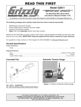
Figure 1. Crate inventory.
A
B
C
NOTICE
If you cannot find an item on this list, care-
fully check around/inside the machine and
packaging materials. Often, these items get
lost in packaging materials while unpack-
ing or they are pre-installed at the factory.
Inventory
The following is a list of items shipped with your
machine. Before beginning setup, lay these items
out and inventory them.
If any non-proprietary parts are missing (e.g. a
nut or a washer), we will gladly replace them; or
for the sake of expediency, replacements can be
obtained at your local hardware store.
Crate 1 (Figure 1) Qty
A. English Wheel ............................................ 1
B. Upper Wheel, Flat ...................................... 1
C. Support Legs .............................................. 1
Figure 2. Box 1 contents, upper wheels.
D
E
F
Box 1 (Figures 2–4) Qty
D. Upper Wheel, Narrow Ridge ...................... 1
E. Upper Wheel, Wide Ridge.......................... 1
F. Upper Wheel Mounting Shafts ................... 2
Hardware Bag (Not Shown)
• Cap Screws M8-1.25 x 25 (Support Legs) . 4
• Lock Washers 8mm (Support Legs) ........... 4
• Flat Washers 8mm (Support Legs) ............ 4
• Cap Screws M8-1.25 x 15 (Storage Brkt) . 22
• Lock Washers 8mm (Storage Bracket) .... 22
• Flat Washers 8mm (Storage Bracket) ...... 22
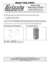
Figure 4. Box 1 contents, lower wheels.
I
J
K
L
M
N
O
P
Q
I. Lower Wheel, Wide Groove ....................... 1
J. Lower Wheel, Narrow Groove .................... 1
K. Lower Wheel, Flat, 3" Diameter.................. 1
L. Lower Wheel, Flat, 2.43" Diameter ............. 1
M. Lower Wheel, Step Roller ........................... 1
N. Lower Wheel,
1
⁄8" Dome, 6" Radius ............ 1
O. Lower Wheel,
1
⁄4" Dome, 6" Radius ............ 1
P. Lower Wheel,
1
⁄2" Dome, 6" Radius ............ 1
Q. Lower Wheel,
3
⁄4" Dome, 6" Radius ............ 1
Figure 3. Box 1 contents, storage brackets.
G
H
G. Lower Wheel Storage Brackets .................. 9
H. Upper Wheel Storage Brackets .................. 2

-10-
Model T27621 (Mfd. Since 2/16)
The unpainted surfaces of your machine are
coated with a heavy-duty rust preventative that
prevents corrosion during shipment and storage.
This rust preventative works extremely well, but it
will take a little time to clean.
Be patient and do a thorough job cleaning your
machine. The time you spend doing this now will
give you a better appreciation for the proper care
of your machine's unpainted surfaces.
There are many ways to remove this rust preven-
tative, but the following steps work well in a wide
variety of situations. Always follow the manufac-
turer’s instructions with any cleaning product you
use and make sure you work in a well-ventilated
area to minimize exposure to toxic fumes.
Before cleaning, gather the following:
• Disposable rags
• Cleaner/degreaser (WD•40 works well)
• Safety glasses & disposable gloves
• Plastic paint scraper (optional)
Basic steps for removing rust preventative:
1.
Put on safety glasses.
2.
Coat the rust preventative with a liberal
amount of cleaner/degreaser, then let it soak
for 5–10 minutes.
3.
Wipe off the surfaces. If your cleaner/degreas-
er is effective, the rust preventative will wipe
off easily. If you have a plastic paint scraper,
scrape off as much as you can first, then wipe
off the rest with the rag.
4.
Repeat Steps 2–3 as necessary until clean,
then coat all unpainted surfaces with a quality
metal protectant to prevent rust.
Gasoline and petroleum
products have low flash
points and can explode
or cause fire if used to
clean machinery. Avoid
using these products
to clean machinery.
Many cleaning solvents
are toxic if inhaled. Only
work in a well-ventilated
area.
NOTICE
Avoid chlorine-based solvents, such as
acetone or brake parts cleaner, that may
damage painted surfaces.
T23692—Orange Power Degreaser
A great product for removing the waxy ship-
ping grease from the non-painted parts of the
machine during clean up.
Figure 5. T23692 Orange Power Degreaser.
Cleanup

Model T27621 (Mfd. Since 2/16)
-11-
Site Considerations
Figure 6. Working clearances.
49
1
/
2
"
26
1
/
2
"
Weight Load
Refer to the Machine Data Sheet
for the weight
of your machine. Make sure that the surface upon
which the machine is placed will bear the weight
of the machine, additional equipment that may be
installed on the machine, and the heaviest work-
piece that will be used. Additionally, consider the
weight of the operator and any dynamic loading
that may occur when operating the machine.
Physical Environment
The physical environment where the machine
is operated is important for safe operation and
longevity of components. For best results, oper-
ate this machine in a dry environment that is
free from excessive moisture, hazardous chemi-
cals, airborne abrasives, or extreme conditions.
Extreme conditions for this type of machinery are
generally those where the ambient temperature
range is outside 41°–104°F; the relative humidity
range is outside 20–95% (non-condensing); or
the environment is subject to vibration, shocks,
or bumps.
Children or untrained people
may be seriously injured by
this machine. Only install in an
access restricted location.
Lighting
Lighting around the machine must be adequate
enough that operations can be performed safely.
Shadows, glare, or strobe effects that may distract
or impede the operator must be eliminated.
Space Allocation
Consider the largest size of workpiece that will
be processed through this machine and provide
enough space around the machine for adequate
operator material handling or the installation of
auxiliary equipment. With permanent installations,
leave enough space around the machine to open
or remove doors/covers as required by the main-
tenance and service described in this manual.
See below for required space allocation.

-12-
Model T27621 (Mfd. Since 2/16)
Assembly
HEAVY LIFT!
Straining or crushing injury
may occur from improperly
lifting machine or some of
its parts. To reduce this risk,
get help from other people
and use a forklift (or other
lifting equipment) rated for
weight of this machine.
3. With help of assistants, raise main frame to
upright position on floor.
Tip: For additional leverage, slide 1" diameter
pipe into lifting eye (see Figure 7) and hold it
while lifting frame.
4. Attach each upper wheel storage bracket to
left side of main frame with (2) M8-1.25 x 15
cap screws, (2) 8mm lock washers, and (2)
8mm flat washers, as shown in Figure 8.
The machine must be fully assembled before it
can be operated. Before beginning the assembly
process, refer to
Needed for Setup and gather
all
listed items. To make sure the assembly pro-
cess goes smoothly, clean all
parts
that have any
heavy-duty rust preventative
applied by the fac-
tory (if applicable).
Figure 8. Upper wheel storage brackets
attached to main frame.
x 4
5. Attach each of nine lower wheel storage
brackets to right side of main frame with (2)
M8-1.25 x 15 cap screws, (2) 8mm lock
washers, and (2) 8mm flat washers (see
Figure 9).
6. Mount English Wheel to floor using fasteners
appropriate for floor type (refer to Anchoring
to Floor on Page 13).
Figure 9. Lower wheel storage brackets
attached to main frame.
Lower
Wheel
Storage
Bracket
Upper Wheel
Storage Bracket
To assemble English Wheel:
1. With help of two assistants, lay English Wheel
frame on its back, as shown in Figure 7.
Note: Place piece of cardboard under frame
to protect paint.
2. Attach support legs to main frame with (4)
M8-1.25 x 25 cap screws, (4) 8mm lock wash-
ers, and (4) 8mm flat washers, as shown in
Figure 7.
Figure 7. Support legs attached.
x 4
Support
Legs
Upper Wheel
Main Frame
Lifting
Eye
x 18

Model T27621 (Mfd. Since 2/16)
-13-
Anchoring to Floor
Lag shield anchors with lag screws (see below)
are a popular way to anchor machinery to a con-
crete floor, because the anchors sit flush with the
floor surface, making it easy to unbolt and move
the machine later, if needed. However, anytime
local codes apply, you MUST follow the anchoring
methodology specified by the code.
Machine Base
Concrete
Lag Screw
Lag Shield Anchor
Flat Washer
Drilled Hole
Figure 10. Popular method for anchoring
machinery to a concrete floor.
Anchoring to Concrete Floors
Number of Mounting Holes ............................ 6
Diameter of Mounting Hardware .................
1
⁄2"
We strongly recommend anchoring the English
Wheel to the floor to prevent it from tipping or
shifting. Because this is an optional step and floor
materials may vary, anchoring hardware is not
included.

-14-
Model T27621 (Mfd. Since 2/16)
SECTION 3: OPERATIONS
Operation Overview
The purpose of this overview is to provide the nov-
ice machine operator with a basic understanding
of how the machine is used during operation, so
the
machine controls/components
discussed later
in this manual
are easier to understand.
Due to the generic nature of this overview, it is
not intended to be an instructional guide. To learn
more about specific operations, read this entire
manual and
seek additional training from expe-
rienced
machine operators, and do additional
research outside of this manual by reading "how-
to" books, trade magazines, or websites.
To complete a typical operation, the operator
does the following:
1. Puts on safety glasses, leather boots, and
leather gloves.
2. Deburrs sharp edges (see Accessories on
Page 24 for optional deburring tool).
3. Cleans workpiece and wheels thoroughly and
removes all abrasive particles.
4. Turns upper wheel handle clockwise to raise
upper wheel bracket against frame.
5. Installs lower wheel with greatest radius
(least amount of curve).
6. Verifies distance between bottom of upper
wheel and top of lower wheel are about an
inch apart, and adjusts distance with height
handwheel.
7. Engages quick-release lever to raise lower
wheel to operating position.
8. Marks approximate 1" frame around
workpiece (refer to Page 15), then inserts
workpiece between wheels.
9. Rotates lower adjustment handwheel until
there is just enough pressure to prevent
workpiece from skipping or slipping.
10. Moves workpiece back and forth through
wheels using a tracking pattern (refer to Page
20), rolling it up to an edge, rotating it slightly,
then pulling it back.
11. When workpiece no longer stretches, rotates
adjustment handwheel clockwise to slightly
increase pressure.
12. When maximum wheel pressure is reached
and workpiece no longer moves through
wheels, disengages quick-release lever, and
changes lower wheel to next lower radius.
13. Repeat Steps 3–12 until curve is attained.
To reduce your risk of
serious injury, read this
entire manual BEFORE
using machine.
If you are not experienced with this type
of machine, WE STRONGLY RECOMMEND
that you seek additional training outside of
this manual. Read books/magazines or get
formal training before beginning any proj-
ects. Regardless of the content in this sec-
tion, Grizzly Industrial will not be held liable
for accidents caused by lack of training.
Bodily injury could result from using this
machine. Always wear safety glasses,
leather gloves, and steel toe footwear when
operating machine or handling sheet steel.

Model T27621 (Mfd. Since 2/16)
-15-
Tracking Tips
• Stretching metal into a curve should be
a gradual process. Always start with just
enough wheel pressure to prevent the
workpiece from skipping or slipping through
the wheels. After the initial curve has formed,
increase the pressure slightly and continue
stretching the metal. Repeat this process
until the desired curve is attained. Using too
much pressure will damage the workpiece
surface and produce poor results.
• Start with the lower wheel that has the great-
est radius (least amount of curve), then
decrease the wheel radius a step at a time
until the desired curve is reached.
• Mark the workpiece with a non-permanent
marker to make it easier to follow tracking
patterns or contour the metal.
• Practice with a scrap piece that is the same
material and thickness as the final workpiece.
• Leave a frame around the workpiece of
approximately 1" that does not go through
the wheels (see Figure 11). As the center of
the workpiece stretches and the frame does
not, the metal is forced to bend into a curve.
Some workpieces may need a larger frame
to accomodate expansion of the metal and
removal of excess material, if needed.
Frame
...and so on
Figure 11. Example of frame around workpiece
and basic back-and-forth tracking pattern.
• Overlap each pass with the previous one in
a smooth, back-and-forth movement through
the wheels, as shown in Figure 11. There
are many patterns of tracking that will pro-
duce different results. Refer to Page 20 for
additional tracking patterns. Choosing the
correct pattern for your operation is a matter
of research and experience.
• Try using the lightest wheel pressure possible
to shape the workpiece. Too much pressure
will crease or ruin the metal. Light pressure
is best for smoothing; higher pressure is best
for rough shaping.
• Take your time. Start rolling slowly and
increase your speed. Many passes through
the wheels with gradual increases in pres-
sure and lower wheel radii will produce good
results and reduce the risk of damaging the
workpiece surface.

-16-
Model T27621 (Mfd. Since 2/16)
Replacing Wheels
To replace upper wheel:
1. Raise lower wheel until both wheels touch.
This ensures upper wheel is supported.
2. Remove two cap screws and locking plate
shown in Figure 12.
3. Turn upper wheel handle (see Figure 12)
clockwise to lock upper wheel bracket against
frame so upper wheel will not move.
Note: Use one hand to steady bracket to pre-
vent it from rotating while turning handle.
Tools Needed Qty
Hex Wrench 4mm .............................................. 1
Brass Punch ...................................................... 1
Hammer ............................................................. 1
A flat upper wheel is pre-installed on the English
wheel. It can be replaced with either of the two
grooved upper wheels. Also, any of the nine lower
wheels can be replaced.
CRUSHING HAZARD! Hold an upper wheel
securely when installing or removing it
or it may fall on your foot! Wear steel toe
footwear to protect your feet.
4. While an assistant holds upper wheel, remove
upper wheel axle and spacers, as shown in
Figure 13.
Figure 13. Using punch and hammer to remove
upper wheel axle.
5. Carefully remove upper wheel, install includ-
ed mounting shaft in wheel, and place wheel
on upper wheel rack.
6. Place new upper wheel between upper wheel
bracket arms (see Figure 13).
Note: Adjust lower wheel height if you have
difficulty replacing upper wheel.
7. Align wheel bearing hole and spacers with
upper wheel bracket mounting holes, then
drive axle through components (in reverse of
Figure 13). Make sure detent on right side
of axle faces up (see Figure 14) so it can be
secured properly.
8. Re-install locking plate and cap screws
removed in Step 2.
Figure 14. Axle re-installed with detent facing
up.
Axle
Figure 12. Location of cap screws and plate that
secure upper wheel axle.
Locking
Plate
Upper Wheel Handle
Detent
Upper
Wheel Axle
Arms

Model T27621 (Mfd. Since 2/16)
-17-
To replace lower wheel:
1. Disengage quick-release lever (see
Figure 15) and lower the lower wheel bracket
until it stops.
The wheels can be positioned perpendicular to
the frame (Figure 16, A) for long workpieces
or parallel to the frame (Figure 16, B) for wide
workpieces.
Figure 16. Wheels positioned to accommodate
different workpiece sizes.
A B
Rotating Wheels
Figure 15. Quick-release lever disengaged.
2. Remove lower wheel and replace it with
another one.
3. Engage quick-release lever and raise lower
wheel to operating position.
Lower Wheel
Bracket
Lower Wheel
Quick-
Release
Lever
PINCHING/CRUSHING HAZARD! Avoid
placing fingers in wheel path during
operation.
To rotate wheels:
1. Loosen two hex bolts (see Figure 17) on
lower wheel adjustment shaft several turns.
Figure 17. Location of hex bolts on lower wheel
adjustment shaft.
Lower Wheel
Adjustment
Shaft
2. Disengage quick-release lever, lower the
lower wheel bracket, then remove lower
wheel.

-18-
Model T27621 (Mfd. Since 2/16)
3. Lift lower wheel bracket until screw shown in
Figure 18 reaches top of groove in adjust-
ment shaft.
8. Re-install lower wheel, engage quick-release
lever, and raise lower wheel to operating
position.
The quick-release lever is adjusted at the factory.
However, due to variables involved with shipping,
it may need to be adjusted.
If the set screws on the steel cams do not engage
the detents on the quick-release lever, the lever
shaft will slip in the cams, causing it to malfunction.
Tools Needed:
Hex Wrench 3mm .............................................. 1
To adjust quick-release lever:
1. Examine detents (see Figure 20) on both
sides of quick-release lever.
Adjusting Quick-
Release Lever
Detent
(1 of 2)
2. If set screws do not contact all four detents,
loosen set screws, turn cams to align set
screws with detents, then tighten set screws.
Figure 20. Tightening cam set screw.
Cam Set
Screws
Detent
Figure 18. Screw at top of groove with lower
wheel bracket lifted.
Screw
5. Lower the lower wheel bracket until it comes
to a stop.
6. Turn upper wheel handle counterclockwise
several turns to lower upper wheel bracket.
Note: Use one hand to steady bracket to pre-
vent it from rotating while turning handle.
7. Rotate upper wheel 90º (see Figure 16, A
on Page 17), then raise upper wheel bracket
until it is seated against frame, making sure
edges of bracket and frame are flush.
4. Rotate lower wheel bracket counterclockwise
until it reaches opposite end of groove, as
shown in Figure 19.
Figure 19. Rotating lower wheel bracket.
Groove
Screw
Groove
Lower
Wheel
Bracket
/